
Optimization of Coil Parameters for a Nonlinear Two
Degree-of-Freedom (2DOF) Velocity-amplified Electromagnetic
Vibrational Energy Harvester
Eliabetta Boco
1
,Valeria Nico
1
, Declan O’Donoghue
1
, Ronan Frizzell
2
, Gerard Kelly
2
and Jeff Punch
1
1
CTVR, Stokes Institute, University of Limerick, Plassey, Limerick, Ireland
2
Efficient Energy Transfer (ηET) Dept, Bell Labs, Alcatel-Lucent, Dublin, Ireland
Keywords:
Energy Harvesting, Nonlinearity, Multiple Degree of Freedom, Electromagnetic Optimization, Modelling.
Abstract:
A 2DOF velocity amplified electromagnetic vibrational energy harvester is analyzed. The system consists of
two masses, one larger than the other, oscillating relative to each other in response to external excitation. The
large mass is designed with a centrally located cavity into which a second smaller mass is placed. This con-
figuration allows the larger mass to impart momentum to the smaller mass during impact, which significantly
amplifies the velocity of the smaller mass. By coupling high strength magnets (placed on the larger mass) and
a coil (embedded in the smaller mass), an electric current is induced in the coil through the relative motion of
the two masses. To intensify the magnetic field, the magnets are arranged with alternating polarity within the
soft-iron body of the larger mass. Between the two masses, and between the larger mass and the support, four
springs are placed. The smaller mass is designed to disconnect from the larger mass, when input vibrations of
sufficient magnitude are present, and this leads to significant nonlinearity in the system response, which is well
described by its transfer function. The nonlinearity leads to an increased bandwidth over which the system
can harvest energy. As a further improvement, the energy harvester is optimized by changing the properties
of the coil. Four different coils are compared in terms of their voltage and power output. Finally, a theoretical
model is proposed in order to predict the optimal configuration.
1 INTRODUCTION
From the invention of the first transistor in 1947
made by John Bardeen, Walter Brattain, and William
Shockley, the number of transistors in Integrated Cir-
cuits (ICs) has followed Moore’s law, basically dou-
bling approximately every two years. An increas-
ing number of transistors, however, has not only led
to more powerful devices, but also increased power
consumption. Moreover, nowadays Information and
Communication Technologies (ICTs) are used in al-
most all fields of everyday life, so that the global
power demand is constantly increasing, mainly in-
volving a greater number of sensors and micro and
nano-scales device (i.e. wireless sensors networks for
temperature or pressure in buildings, industrial plants
or in the environment). Energy harvesting comes
from the necessity to address this increasing power
demand and aims to extract energy already present in
the environment in many forms, such as temperature
gradients, vibrations and electromagnetic waves, and
use this energy to power low-power consuming elec-
tronic devices.
Vibrations are one of the most appealing kinds of
ambient energy: they are always present, at any scale,
and their intensity can be very different depending on
the surrounding conditions. There are many possi-
ble ways to convert vibrational energy: piezoelectric,
electromagnetic or variable capacitors. In this work,
the electromagnetic conversion method is used, be-
cause it is applicable at many scales and it can pro-
duce quite high power densites provided that there
is high relative velocity between the magnet and coil
(Waters et al., 2008). Nonlinear systems are advanta-
geous compared to linear systems since although lin-
ear systems have a higher response at resonance, non-
linear systems are more flexible because they do not
need to be tuned, i.e. they are naturally able to harvest
energy from broad band excitations. In this manner, a
single nonlinear device can be used in many different
applications and can be efficient even if the excitation
frequency spectrum is not constant in time, which is a
feature of many real vibration profiles (Cottone et al.,
2009; Leadenham and Erturk, 2014).
119
Boco E., Nico V., O’Donoghue D., Frizzell R., Kelly G. and Punch J..
Optimization of Coil Parameters for a Nonlinear Two Degree-of-Freedom (2DOF) Velocity-amplified Electromagnetic Vibrational Energy Harvester.
DOI: 10.5220/0005411901190128
In Proceedings of the 4th International Conference on Smart Cities and Green ICT Systems (SMARTGREENS-2015), pages 119-128
ISBN: 978-989-758-105-2
Copyright
c
2015 SCITEPRESS (Science and Technology Publications, Lda.)
The first part of the paper presents the experi-
mental characterization of a two degree-of-freedom
(2DOF) velocity-amplified electromagnetic energy
harvester. To exploit nonlinearities, and to provide
velocity amplification, an uncoupled 2DOF system
is used: a 2DOF harvester can enlarge the energy
conversion bandwidth (Wu et al., 2012b; Wu et al.,
2012a; Jang et al., 2011), but it does not improve the
harvesting capability for random excitations as long
as the masses are coupled (Jang et al., 2012). More-
over, for electromagnetic conversion the most impor-
tant feature is the high relative velocity between coil
and magnets: in order to have velocity amplification
through the momentum transfer between two impact-
ing masses, the masses need to beuncoupled. A trans-
fer function analysis is used to describe the observed
nonlinearity in detail. Following this, an optimization
process for designing the coil of the electromagnetic
generator is proposed. Finally, a numerical model is
presented, which can be used to predict the optimal
coil settings for a given volume.
2 TRANSFER FUNCTION
CHARACTERISATION
The main purpose of this section is to investigate the
nonlinear response of a 2DOF vibration energy har-
vester. In order to do so, the system was tested experi-
mentally under different levels of acceleration and the
transfer function is used to highlight nonlinearities in
the system response.
2.1 Experimental Setup and Procedure
The system consists of a large mass, where four mag-
nets are orientated in the configurations shown in
Fig.1. The large mass can move between two springs
which are attached to the outer housing that serve to
transfer energy from the vibrating base into the larger
mass itself. A smaller mass, enclosed within the cav-
ity of the larger mass is designed to separate from the
larger mass when sufficient excitation is present. This
configuration allows the larger mass to impart mo-
mentum to the smaller mass during impact, which sig-
nificantly amplifies the velocity of the smaller mass.
(Cottone et al., 2014; Nico et al., 2014; O’Donoghue
et al., 2014). All impacting surfaces have high Q
springs attached to mediate the impacts and efficiently
transfer loads. The volume of the outside mass is
1.29 · 10
-4
m
3
. The closed loop system used to con-
trol the LDS V406 permanent magnet shaker from
Bruel&Kjaer is shown schematically in Fig.2. Out-
put signals from the Dactron Comet shaker control
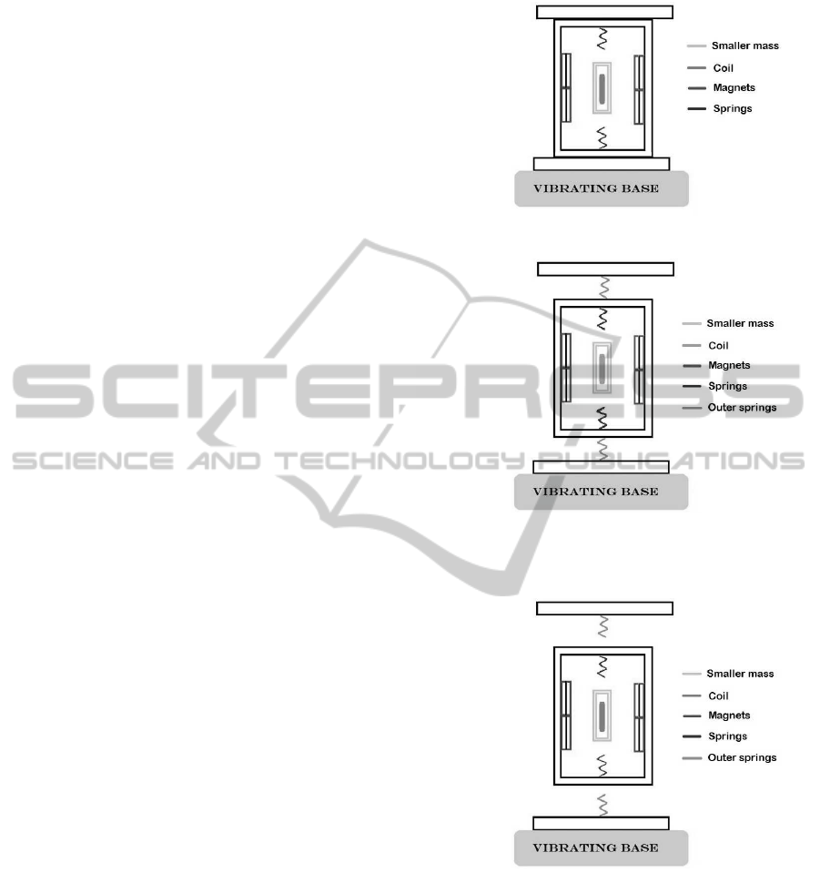
(a) Configuration (1): outer mass is steady
(b) Configuration (2): the movement of the outer mass is
constrained by the cap. The springs are always connected
to the large mass, so that it always experiences the elastic
force.
(c) Configuration (3): the outer mass is free to move.
Figure 1: Schematic of the 2DOF energy harvester. The
coil is embedded in a smaller mass which oscillates between
four magnets that provide a strong magnetic field. The big
mass oscillates outside in configuration (2) and (3) while it
is fixed in configuration (1). The collisions between the two
masses provide the velocity amplification.
system were amplified using the LDS TPO 25 Power
Oscillator and used to drive the shaker and the voltage
response of the harvester for each coil was measured
using LabView through an appropriate data acquisi-
tion card. For each coil, data havebeen acquired using
SMARTGREENS2015-4thInternationalConferenceonSmartCitiesandGreenICTSystems
120
the load resistance which maximized the power out-
put. A high sensitivity (1.96mV/g) PCB Piezotronic
accelerometer was employed to provide feedback to
the controller in order to ensure that the correct accel-
eration levels were applied.
To fully characterize the system, two configura-
tions were tested (see Fig.1 (a) and (b)): (1) mo-
tion of the larger mass was prevented and so only
the smaller mass was free to oscillate and (2) mo-
tion of the smaller mass was free but motion of the
larger mass was restricted by the top of the housing
which was lowered to ensure the larger mass could
not detach from its supporting springs (this meant that
spring forces were always active on the larger mass).
These configurations allowed different modes of op-
eration of the 2DOF system to be investigated to bet-
ter understand the response of the system.
Figure 2: Experimental setup.
In configuration (1), the response of the smaller
mass could be investigated in isolation, while the
coupled response was examined using configuration
(2). The response of each of these configurations
varied considerably depending on the magnitude of
the input acceleration, as this controlled whether the
masses decouple from each other or not. For exam-
ple, when the input acceleration was sufficiently low
(from a=0.05g to a=0.2g) the larger mass did not os-
cillate in any configuration and the spring on the un-
derside of the smaller mass remained in contact with
the larger mass. Under such excitation levels, config-
uration (1) behaved linearly, while system (2) could
be considered to be a a pair of coupled harmonic os-
cillators. In addition there where further nonlineari-
ties due to the electromagnetic conversion.
Under higher levels of excitation (a=0.5g), the
smaller mass in configuration (1) received sufficient
energy to break contact with the larger mass, lead-
ing to nonlinearity in the system response. This was
caused by the fact that while the smaller mass is de-
tached from larger mass, there is no elastic spring
force acting on it. This means that the effective elas-
tic constant experienced by the system depends on the
time that each mass is moving freely in the detached
configuration. Higher accelerations also allowed such
changes in the system’s effective elastic constants to
affect configuration (2), resulting in the system acting
as coupled 2DOF oscillators with a softening nonlin-
earity.
To verify these empirical observations, the differ-
ent configurations were tested under increasing and
decreasing sine wave frequency sweeps (from 5 to
100 Hz in 260 seconds) with different amplitudes of
accelerations, as in Fig.3 and Fig.4, and the voltage
output was recorded. Finally, the transfer function
was calculated for each configuration as described in
the following section.
2.2 Transfer Function Analysis
Let y(t) be the output of our system, and let x(t) be the
input. Let X(f) and Y(f) be the Laplace transforms of
the input and the output respectively.
X(s) =
Z
+∞
−∞
x(t)e
−st
dt (1)
Y(s) =
Z
+∞
−∞
y(t)e
−st
dt (2)
Where
s = jω (3)
The Laplace transform is equal to the Fourier trans-
form, and represents the frequency behaviour of the
system.
So, for a linear system, the transfer function is de-
fined as:
H(ω) =
Y(ω)
X(ω)
(4)
When the system is linear, H(ω) is a well-defined
mathematical function, because it has a unique value
for each value of ω, whereas for a nonlinear system it
depends also on the shape and amplitude of the input
signal. This means that the transfer function is not
mathematically well defined for nonlinear systems.
Nonetheless, transfer function analysis is a very
useful method to know if a system is linear or not for
different input signals, (Muller and Massarani, 2001),
as deviations from linearity result in distinct varia-
tions in the transfer function, as will be discussed in
the next section.
2.3 Transfer Function Results
Comparing the resulting spectrum from the transfer
function analysis in Fig.3 to a simple linear response
is the first method to detect nonlinearity in a system.
A linear response is characterized by a sharp res-
onant peak that is symmetric about that peak. Fig.3
shows that nonlinearity due to the change in the ef-
fective stiffness of the springs is evident as the ac-
celeration increases. This is caused by the smaller
OptimizationofCoilParametersforaNonlinearTwoDegree-of-Freedom(2DOF)Velocity-amplifiedElectromagnetic
VibrationalEnergyHarvester
121
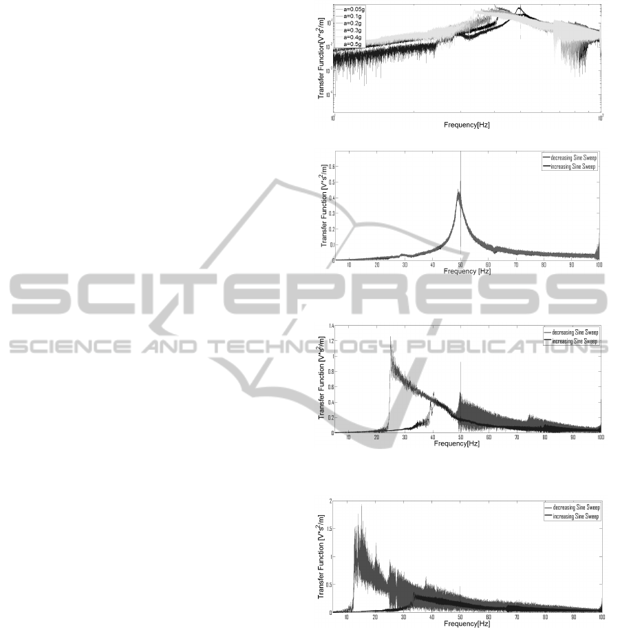
mass spending more and more time detached from the
springs with increasing acceleration which led to a re-
duction of the resonant frequency of the system due
to a decrease in the effective stiffness, an effect that is
more pronounced for higher acceleration levels. The
overall shape of the power spectrum varies for the
different cases indicating deviation from linear be-
haviour. For example at very low acceleration ampli-
tude (a=0.05g), in configuration (1) , the behaviour is
linear and the resonant peak is sharp and symmetric,
as shown in Fig.3 (b). By increasing the acceleration,
the resonant frequency decreases to lower frequencies
becoming more and more asymmetric but displaying
a broader band response (Fig.3 (a)). Very similar re-
sponses are seen for configuration (2) in Fig.4 (a) and
(b)
The second fingerprint of nonlinearity in the trans-
fer function characterization is the hysteresis phe-
nomenon. In a linear system, a sine sweep that is
increasing or decreasing in frequency as the excita-
tion signal results in the same system response. In a
nonlinear system, however, the behaviour for increas-
ing or decreasing sweeps are different: as already
stated, the transfer function is not a mathematically
well-defined function for nonlinear systems as it can
havetwopossible values for the same input frequency,
one for the increasing sweep and one for the decreas-
ing sweep (Leadenham and Erturk, 2014). The trans-
fer function analysis in Fig.3 shows this hysteresis for
configuration (1).
The same analysis has also been conducted using
configuration (2), in order to investigate the effect of
the impacts (Fig.4). The frequency shifting is quite
similar when the outer mass started to fully compress
the springs Fig.4 (c), (d) and (e). Then the effect of
the velocity amplification became dominant, and the
frequency response shifted to very low frequency, due
to the larger mass, and the output increased by about
an order of magnitude Fig.4 (b). The noisy behaviour
outside resonance is due to the fact that using the
sine sweep method to measure the transfer function
is not the most robust to noise (Muller and Massarani,
2001).
An alternative more precise method, is an analysis
through single harmonics excitation. This method is
slower than a sine sweep, however, and since the non-
linear effects are very well evident despite the noise,
it was not considered necessary.
Improvements to the results could be achieved by
conducting a statistically relevant number of tests and
averaging them. The main problem with linear os-
cillators as energy harvesters, is that they are only
able to harvest energy effectively from a narrow fre-
quency range around their natural resonance. This
(a) Transfer function with the outer mass steady
(b) Hysteresis in the almost linear case. The output has
been acquired at a=0.05g so that the smaller mass cannot
detach from the springs
(c) Hysteresis with a=0.2g acceleration. The acceleration
in input is a=0.2g, so that the smaller mass is starting to
detach from the springs
(d) Hysteresis with a=0.5g acceleration. The acceleration
a=0.5g is enough to let the smaller mass detach from the
springs and spend more time decoupled from the larger
mass leading to a decrease in the resonant frequency.
Figure 3: Measured transfer functions and hysteresis for
configuration (1).
leads to a serious difficulty when reducing linear os-
cillator in size as, the smaller the system the higher
the resonance frequency: a mm scale harvester would
have a natural frequency in the kHz range, whereas
real-world vibrations are usually under few thousands
of Hz (Mizuno and Chetwynd, 2003; Rebeiz et al.,
1987).
High natural frequencies are not compatible with
SMARTGREENS2015-4thInternationalConferenceonSmartCitiesandGreenICTSystems
122
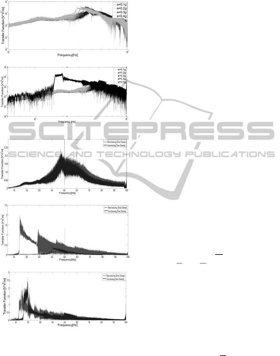
(a) Transfer Function with the outer mass starting to move
(b) Transfer Function with the outer mass fully compress-
ing the springs
(c) Hysteresis in the almost linear case, a=0.1g
(d) Hysteresis with a=0.3g acceleration
(e) Hysteresis with a=0.5g acceleration
Figure 4: Measured Transfer Functions and Hysteresis for
configuration (2).
many real-world vibrations, which are often charac-
terised by low frequency, broad spectrum and are usu-
ally not constant in time. The analysis conducted here
reveals that the response of a nonlinear energy har-
vester is more suitable for a broad band excitation,
and that the scale is not the only factor to determine
the frequency response, since the softening effect can
also shift the resonance. There is the possibility also
to use the nonlinear response to control the resonance
frequency, however how much control is possible will
need to be determined on a system-by-system basis.
3 OPTIMIZATION
3.1 Theoretical Model
An electromagnetic energy harvester can be described
by a system of two coupled equations: the first is the
equation of motion of the device, the second is the
voltage output. The value of the magnetic flux into the
coil acts as the coupling coefficient. (Bouendeu et al.,
2011; Poulin et al., 2004). In this paper, a numerical
model is proposed to predict the optimum coil param-
eters for a given magnetic field. Of particular interest
are the wire diameter and number of turns that opti-
mize the voltage and power output of the harvester.
The procedure used in this analysis was to select
different wire diameters for a fixed internal radius and
coil height, and then determine the resulting coil pa-
rameters; namely the coil length (l), coil resistance
(R
c
) and coil inductance (L). The parameters for the
different wire diameters were then used to solve the
system equations for a single-dof (1DOF) system as
in configuration (1) in orderto determine the optimum
wire diameter.
The system to solve is:
(
M¨z = −k
ef f
z− γ˙z−
BlV
R
L
− Asin(ωt)
˙
V =
R
L
L
(Bl˙z−
R
C
R
L
V −V)
(5)
where z is the relative displacement between the mag-
net and coil, M is the inertial mass, γ is the mechanical
damping, B is the magnetic field, l is the length of the
wire, R
L
is the load resistance, L is the inductance, R
C
is the coil resistance and V is the induced voltage.
To be able to predict the optimum coil wire diam-
eter, the coil internal radius (r
i
), the number of turns
(Nturns) and the wire diameter itself (d
w
) have been
fixed in each simulation. From these parameters, it is
possible to obtain:
Nturns
h
=
t f
d
(6)
where Nturns
h
is number of wire turns along the
height of the coil, t is the thickness of the coil, f is
the fill factor and d is the diameter of the wire.
OptimizationofCoilParametersforaNonlinearTwoDegree-of-Freedom(2DOF)Velocity-amplifiedElectromagnetic
VibrationalEnergyHarvester
123
Nturns
sur f
=
Nturnsf
Nturns
h
(7)
where Nturns
sur f
is the number of wire turns along
the radial direction.
The outer radius of the coil is dependent on the
number of turns and on the wire radius:
ro = ri+ dNturns
sur f
(8)
where ro and ri are respectivelythe outer and the inner
radius of the coil.
The coil length is given by:
l = Nturns(ro+ ri)π; (9)
The coil resistance can be determined from the wire
length and resistivity:
Rc =
ρl
(π(D/2)
2
)
(10)
where R
c
is the coil resistance, ρ is the resistivity of
the wire and D is the diameter of the coil.
The coil inductance (given in µH) can then be
determined from Wheelers formula (Wheeler, 1942;
Wheeler, 1928):
L = 0.02
[(ro + ri)/2]
2
Nturns
2
6(ro+ ri)/2+ 9t+ 10(ro − ri)
(11)
where ro, ri, t are in mm.
The mass of the coil is given by:
m
B
= t fπ(
ro + ri
2
)
2
ρ
m
(12)
where ρ
m
is the copper mass density and m
B
is the
coil mass.
m
B
is an important quantity since the coil is em-
bedded in the mass in this analysis and so contributes
to the total inertial mass (M) given by:
M = m+ m
B
(13)
where m is the mass of the coil housing.
The system of equations has been solved with the
Heun method, to avoid numerical divergence (Gras-
selli and Pelinovsky, 2008). The device is assumed
to be in configuration (1) from Fig.1, with the smaller
mass always attached to the springs.
The Power output has been calculated using R
L
= R
C
and an effective spring constant has been cal-
culated in order to match the experimental resonance
frequency using the experimental value of the little
mass (around 0.02 kg, slightly vaying with the mass
of each coil).
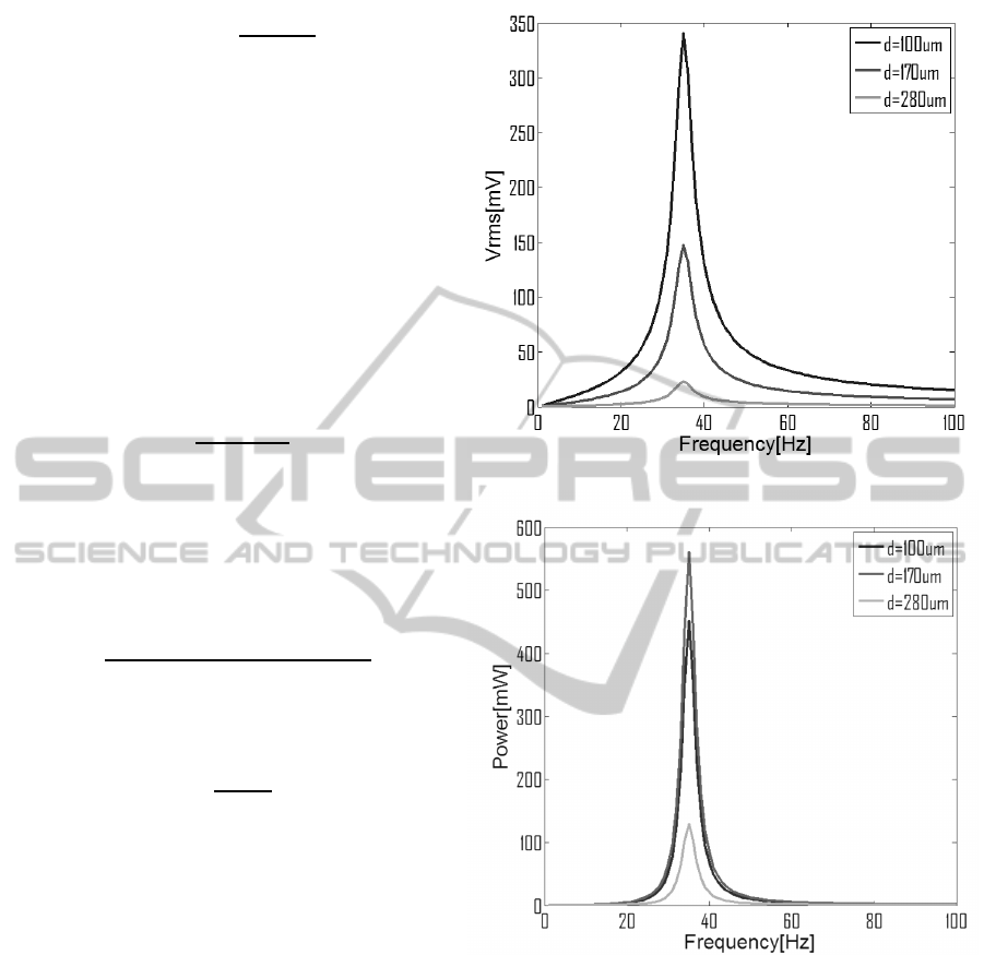
Fig.5 shows simulation results for three different
wire diameters for the 1DOF system with an input ac-
celeration of a=0.4g. The results show that although
(a) Simulated voltage output with RL=RC for the three coils
(b) Simulated power output with RL=RC for the three coils
Figure 5: Simulation results in linear approximation for the
transducer only.
the smallest wire diameter gives the highest voltage,
the power is optimized using the intermediate wire di-
ameter of 170 µm. The ability to represent this type of
effect is useful in order to ensure optimum coil param-
eters are found. The approach can also be extended to
the analysis of multi-mass systems.
In the following section experimental results are
used to verify that the optimum coil wire diameter
found through simulation is correct for the actual sys-
tems of interest to this paper.
SMARTGREENS2015-4thInternationalConferenceonSmartCitiesandGreenICTSystems
124
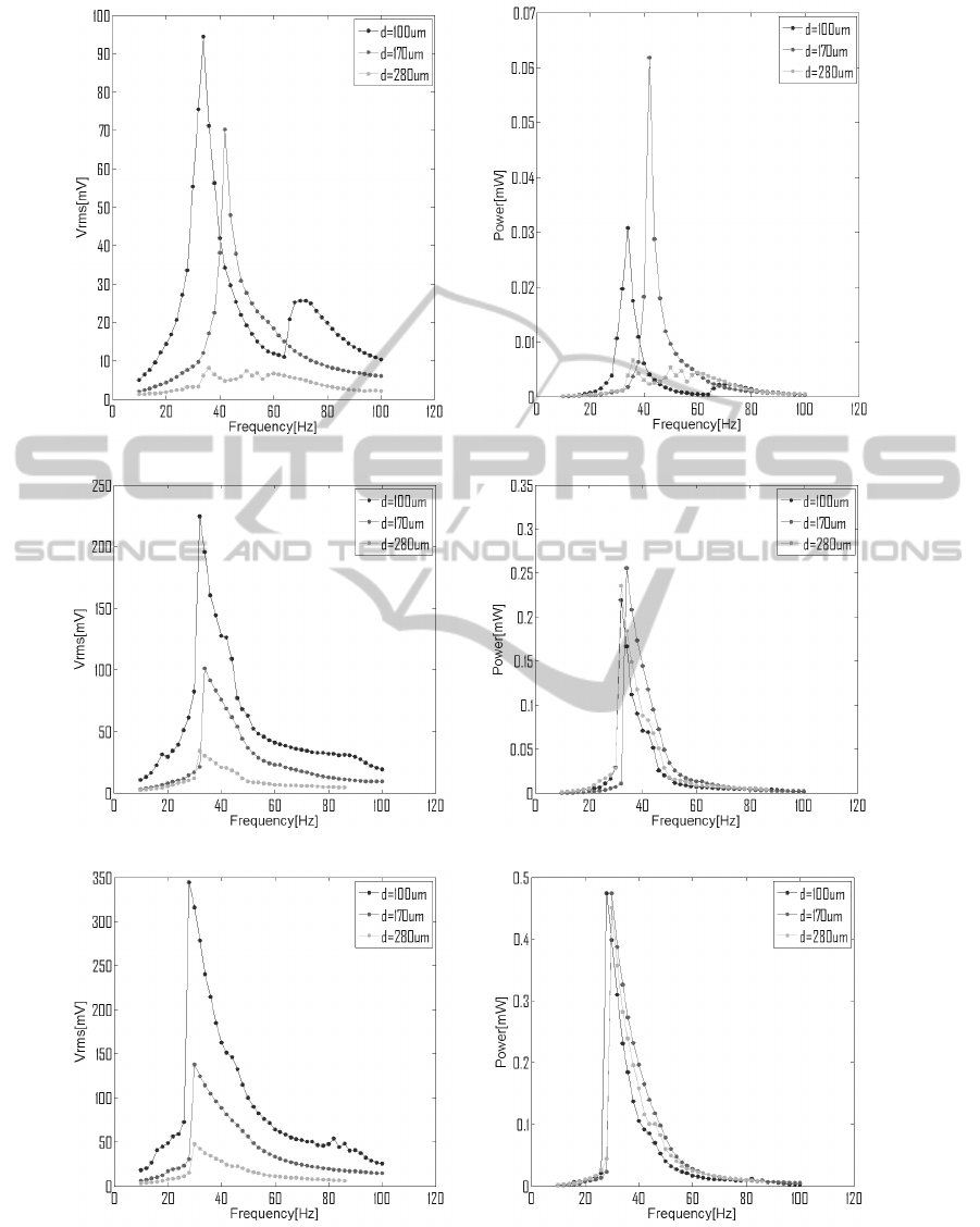
(a) Voltage output at a=0.2g ( b) Power output at a=0.2g
(c) Voltage output at a=0.4g (d) Power output at a=0.4g
(e)Voltage output at a=0.6g (f)Power output at a=0.6g
Figure 6: Voltage and power output comparison at different acceleration levels in configuration (1).
OptimizationofCoilParametersforaNonlinearTwoDegree-of-Freedom(2DOF)Velocity-amplifiedElectromagnetic
VibrationalEnergyHarvester
125
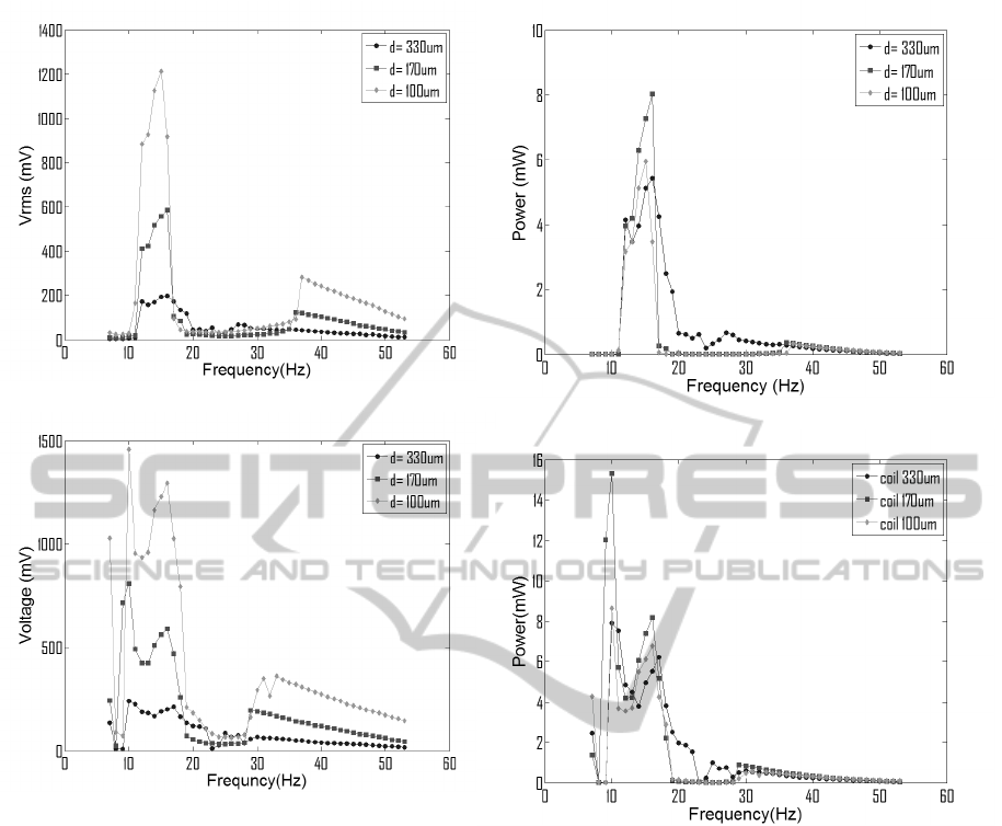
(a) VoltageOutput at a=0.4g
(b) VoltageOutput at a=0.6g
Figure 7: Voltage output for the three coils at different level
of accelerations for configuration (3).
3.2 Experimental Validation of
Optimum Coil Wire Diameter
The same experimentalsetup shown in Fig.2 was used
to generate the results in this section. Configura-
tions (1) and (3) from Fig.1 were tested. Three dif-
ferent wire diameters were analyzed in order to de-
termine the most reasonable wire to use for winding
the coil in terms of voltage and power output. The
wire diameters selected were based on the modelling
of the previous section and the experimental results
serve to verify the model. Different levels of accel-
eration (a=0.2g, a=0.4g, a=0.6g) were provided as
input to the two configurations of interest in order to
verify that the optimal configuration did not change
due to the frequency shifting observed in Section 2.3.
In addition, three levels where imposed to show that
the frequency shifting due to the system nonlinearity
did not influence the optimal value of wire diameter.
(a) Power Output at a=0.4g
(b) Power Output at a=0.6g
Figure 8: Power output for the three coils at different level
of accelerations for configuration (3).
The three coils used had the same volume, but they
used different wire diameters of 100µm, 170µm and
280µm.
Each test was conducted by finding the optimal
load resistance for the differentcoils and then measur-
ing the voltage and power output. As a first stage, the
system was optimized for configuration (1): the re-
sults are shown in Fig.6. Although the voltage output
increases with decreasing wire diameter, the power
output shows a maximum for the 170 µm diameter,
before decreasing again for the lowest wire diameter.
This is due to the increasing resistance of the coil it-
self. The same effect is shown for increasing accel-
eration amplitude, as evident by comparing Fig.6 (d)
and (f).
At a=0.6g acceleration for configuration (1), the
difference between the power output produced by the
different coils reduces. This could be due to the fact
SMARTGREENS2015-4thInternationalConferenceonSmartCitiesandGreenICTSystems
126
that the optimization theory is linear, which means
that the system is required to maintain a fixed reso-
nance frequency. This is clearly not true for a non-
linear system: the shifting in the frequency behaviour
affects parameters such as the impedance of the coil,
which is taken into account in the optimization. The
same process was repeated for configuration (3) in
Fig.1, in order to verify the same trends are observed
in a multi-mass system which experiences the veloc-
ity amplification effect. In this case a wire diameter
of d=330µm was used instead of the 280µm diameter
wire. Fig.7 and Fig.8 show that the optimal wire di-
ameter is again 170 µm. The results also show that
at a=0.4g, it is possible to see the two resonant peaks
due to the two masses in motion. At a=0.6g, however,
the nonlinearity of the whole system dominates, lead-
ing to just one large peak and the spectrum becomes
wider.
The broadening of the resonance peak demon-
strates an enhanced energy harvesting capability such
that the system responds to a wider band of input fre-
quencies. It is clear from the results that the model
is capable of predicting the optimum wire diameter,
indicating it is a useful design tool. Further improve-
ments to the model would involve accounting for the
insulation thickness in the coil and using a set of non-
linear equations to model the performance. These
points will be addressed in future work.
4 CONCLUSIONS
In this paper, a 2DOF velocity amplified electromag-
netic energy harvester has been presented. The non-
linearity occurring in the system for different con-
figurations has been analyzed, which highlighted a
softening nonlinearity. This feature has the effect of
shifting the resonance frequencies of the harvester to
lower values and to enlarge the bandwidth of the re-
sponse. Thus it is possible to harvest energy from
a wider band of frequencies, making it unnecessary
to tune the harvester each time the driving frequency
changes. The transfer function characterization also
clearly demonstrates the gain in the output signal due
to velocity amplification.
In the second part of the paper, an optimization
model has been proposed, that is capable of predicting
the most appropriate coil wire diameter for maximum
voltage and/or power. The model employs a linear ap-
proximation, and it has been verified through compar-
ison with three sets of data from different coils. The
experimental tests were carried out using three levels
of acceleration, and it was verified that the optimal
coil configuratondid not change substantially with the
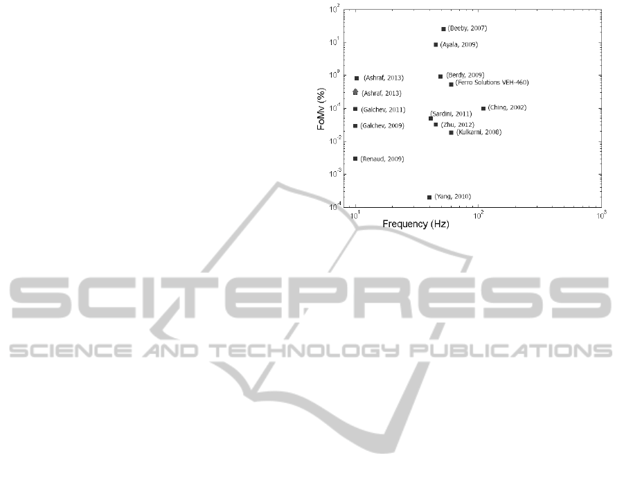
Figure 9: Comparison between recently published FoM
(Ashraf et al., 2013a; Ashraf et al., 2013b; Galchev et al.,
2011; Galchev et al., 2009; Renaud et al., 2009; Beeby
et al., 2007; Ayala et al., 2009; Berdy et al., 2009; Ching
et al., 2002; Sardini and Serpelloni, 2011; Zhu et al., 2012;
Kulkarni et al., 2008; Yang and Lee, 2010) . The diamond
is our first prototype.
frequency shifting that occurs due to the nonlinearity
of the system.
In Fig.9 the comparison with some recently re-
ported energy harvesters in the literature is shown. A
high Figure of Merit (FoM) (Mitcheson et al., 2008;
Ashraf et al., 2013a) demonstrates the effectiveness of
velocity amplification in electromagnetic energy har-
vesting. Until now, there has been no evidence of a fi-
nite lifetime of the analysed harvester due to mechan-
ical failure, even with high accelerations. Future work
will focus on improving the model accuracy through
the introduction of a method to capture the effects of
the nonlinearity of the multi-mass system. Moreover,
the scaling down of the system will be addressed, in
order to enable future integration on vibrating systems
such as bridges or rotating machines.
ACKNOWLEDGEMENTS
The authors acknowledge the financial support
of Science Foundation Ireland under Grant No.
10/CE/I1853and the Irish Research Council (IRC) for
funding under their Enterprise Partnership Scheme
(EPS). This work was financially supported by the In-
dustrial Development Agency (IDA) Ireland.
REFERENCES
Ashraf, Khir, Dennis, and Baharudin (2013a). Improved
energy harvesting from low frequency vibrations by
OptimizationofCoilParametersforaNonlinearTwoDegree-of-Freedom(2DOF)Velocity-amplifiedElectromagnetic
VibrationalEnergyHarvester
127

resonance amplification at multiple frequencies. In
Sensors and Actuators A: Physical. ELSEVIER.
Ashraf, Khir, Dennis, and Baharudin (2013b). A wide-
band, frequency up-converting bounded vibration en-
ergy harvester for a low frequency environment. In
Smart Materials and Structures. IOP Publishing.
Ayala, Zhu, Tudor, and Beeby (2009). Autonomous tunable
energy harvester. In PowerMEMS, 2009.
Beeby, Torah, Tudor, Glynne-Jones, O’Donnell, Saha, and
Roy (2007). A micro electromagnetic generator for
vibration energy harvesting. In Journal of Microme-
chanics and Microengineering. IOP Publishing.
Berdy, Srisungsitthisunti, Xu, Rhoads, Jung, and Peroulis
(2009). Compact low frequency meandered piezoelec-
tric energy harvester. In PowerMEMS, 2009.
Bouendeu, Greiner, Smith, and Korvink. (2011). Design
synthesis of electromagnetic vibration-driven energy
generators using a variational formulation. In Journal
of Microelectromechanical Systems. IEEE.
Ching, Wong, Li, Leong, and Wen (2002). A laser-
micromachined multi-modal resonating power trans-
ducer for wireless sensing systems. In Sensors and
actuators A: Physical. ELSEVIER.
Cottone, Frizzell, Goyal, Kelly, and Punch (2014). En-
hanced vibrational energy harvester based on velocity
amplification. In Journal of Intelligent Material Sys-
tems and Structures. SAGE.
Cottone, Vocca, and Gammaitoni (2009). Nonlinear energy
harvesting. In PhysRevLett, vol.102. American Physi-
cal Society.
Galchev, Cullagh, Peterson, and Najafi (2011). Harvesting
traffic-induced vibrations for structural health moni-
toring of bridges. In Journal of Micromechanics and
Microengineering. IOP Publishing.
Galchev, Kim, and Najafi (2009). A parametric frequency
increased power generator for scavenging low fre-
quency ambient vibrations. In Procedia Chemistry,
Volume 1, Issue 1, September 2009, Pages 14391442.
ELSEVIER.
Grasselli and Pelinovsky (2008). Numerical Mathematics.
Jones & Bartlett Learning.
Jang, Rustighi, Brennan, Lee, and Jung (2011). Design of a
2dof vibrational energy harvesting device. In Journal
of Intelligent Material Systems and Structures. SAGE.
Jang, Rustighi, Brennan, Lee, and Jung (2012). Vibration
energy harvesting from random force and motion ex-
citations. In Journal of Intelligent Material Systems
and Structures. SAGE.
Kulkarni, Koukharenko, Torah, Tudor, Beeby, O’Donnell,
and Roy (2008). Design, fabrication and test of in-
tegrated micro-scale vibration-based electromagnetic
generator. In Sensors and Actuators A: Physical. EL-
SEVIER.
Leadenham and Erturk (2014). M-shaped asymmetric non-
linear oscillator for broadband vibration energy har-
vesting: Harmonic balance analysis and experimental
validation. In Journal of Sound and Vibration,vol.333,
n.23, pag.6029-6223. Elsevier.
Mitcheson, Yeatmann, Rao, Holmes, and Green (2008).
Energy harvesting from human and machine motion
for wireless electronic devices. In Proceedings of the
IEEE. IEEE.
Mizuno and Chetwynd (2003). Investigation of a resonance
microgenerator. In Journal of Micromechanics and
Microengineering 13, 209-216. Institute of Physics
Publishing.
Muller and Massarani (2001). Transfer-function measure-
ment with sweeps. In J. Audio Eng. Soc. AES.
Nico, O’Donoghue, Frizzel, Kelly, and Punch (Septem-
ber 2014). A multiple degree-of-freedom velocity-
amplified vibrational energy harvester part b: Mod-
elling. In ASME 2014 International Conference on
Smart Materials. SMASIS.
O’Donoghue, Nico, Frizzel, Kelly, and Punch (September
2014). A novel velocity amplified vibrational energy
harvester: Experimental analysis. In ASME 2014 In-
ternational Conference on Smart Materials. SMASIS.
Poulin, Sarraute, and Costa (2004). Generation of electrical
energy for portable devices: Comparative study of an
electromagnetic and a piezoelectric system. In Sen-
sors and Actuators A Physical. ELSEVIER.
Rebeiz, Regehr, Rutledge, Savage, and Jr, L. (1987).
Submillimeter-wave antennas on thin membranes.
In International Journal of Infrared and Millimeter
Waves. Springer.
Renaud, Fiorini, Schaijk, V., and Hoof, V. (2009). Har-
vesting energy from the motion of human limbs: the
design and analysis of an impact-based piezoelectric
generator. In Smart Materials and Structures. IOP
Publishing.
Sardini and Serpelloni (2011). An efficient electromagnetic
power harvesting device for low-frequency applica-
tions. In Sensors and actuators A: Physical. ELSE-
VIER.
Waters, Chisum, Jazo, and xFralick (2008). Development of
an electro-magnetic transducer for energy harvesting
of kinetic energy and its applicability to a mems-scale
device. In Nanopower Forum 2008.
Wheeler (1928). Simple inductance formulas for radio
coils. In Proceedings of the I.R.E.
Wheeler (1942). Formulas for the skin effect. In Proceed-
ings of the I.R.E.
Wu, Tang, Yang, and Soh (August 21, 2012b). A novel two-
degree-of-freedom piezoelectric energy harvester. In
Journal of Intelligent Material Systems and Struc-
tures. SAGE.
Wu, Tang, Yang, and Soh (July 22, 2012a). Development of
a broadband nonlinear two-degree-of-freedom piezo-
electric energy harvester. In Journal of Intelligent Ma-
terial Systems and Structures. SAGE.
Yang and Lee (2010). Non-resonant electromagnetic wide-
band energy harvesting mechanism for low frequency
vibrations. In Microsyst Technol (2010) 16:961966.
Springer-Verlag 2010.
Zhu, Beeby, Tudor, and Harris (2012). Vibration energy
harvesting using the halbach array. In Smart Materials
and Structures. IOP Publishing.
SMARTGREENS2015-4thInternationalConferenceonSmartCitiesandGreenICTSystems
128
