
Using Process Ontology Together with Process Editor
To Facilitate Tool Integration
Chanh Duc Ngo
1
, Hanh Nhi Tran
2
and Joel Champeau
3
1
University of Science of HoChiMinh (HCMUS), Hồ Chí Minh, Vietnam
2
Institut de Recherche en Informatique de Toulouse (IRIT), Toulouse Cedex 9, France
3
Ecoles Nationales Supérieures de Techniques Avancées de Bretagne (ENSTA-Bretagne), Brest, France
Keywords: Process Modelling, Collaborative Process, Tool Integration, Model Transformation.
Abstract: Modern software and system collaborative process involves various teams in different development phases
thus need efficient solutions for tools integration. In Model-Driven Development, transformation technique
is used to allow exchanging models created by different tools. However, in a process, transformation are
often defined manually for a tool-incompatible point and rarely reusable. To facilitate the automatic
generation of transformation rules for tool integration, we propose to use process ontology together with
process editor when modelling process. The idea is using ontology to stock process assets from various
sources so that the relations between similar elements in different technical spaces can be established
automatically. The process editor enriches the ontology by process elements captured from modelling
activities. Then the integrated ontology helps the editor detect tool integration points and complete the
process model as well as generate the mappings between concerned process elements.
1 INTRODUCTION
Modern software and system process involves
various teams in different development phases.
Often, each team uses specific tools in their domain
of expertise that are not always compatible with
other teams in the global process. This diversity
makes tool integration an important issue in
collaborative process to enable exchanges of
artefacts during the development (Wasserman,
1990). Model Driven Development (MDD) uses
model transformations to deal with tool integration.
So far, process’s participants identify themselves the
incompatible points in their process and then
develop needed transformations to bridge the gaps.
One problem with this solution is the manual
definition of mappings between models which
hinders transformation reuses.
We seek to remedy this problem by adding
semantics to process models in order to allow the
reasoning on the equivalence between different
process’s elements. The main idea is using ontology
to stock process assets from various sources so that
the relations between similar elements in different
technical spaces can be established automatically.
We integrate ontology into a process editor to
capture process elements from modelling activities
and enrich the process ontology. Then the integrated
ontology can help the editor detect tool integration
points and complete the process model as well as
generate the mappings between concerned process
elements.
This paper presents our work on integrating
process ontology into a process editor (Ngo, 2012).
We propose an extension of the Software and System
Process Engineering Meta-model standard (SPEM
2.0) (OMG, 2008) to describe process elements at
different levels of technical space, from domain-
dependent to tool-dependent. On the one hand, this
refinement allows reusing more pertinent process
elements for a given context. On the other hand, it
brings out the semantic relationships between
process elements which are stocked in an ontology.
We develop an algorithm to analyze a process model
and identify the non-matching points on artefacts
formats (i.e. tool integration points); then we reason
the process ontology stocking these artefacts to
deduce the equivalence relations between them and
create transformation rules.
The paper begins with an example illustrating the
process modeling and tool integration issues
addressed by our work. Section 3 presents our main
propositions on: (1) an extension of SPEM 2.0
enriched with tool-related process elements; (2) an
565
Ngo C., Tran H. and Champeau J..
Using Process Ontology Together with Process Editor - To Facilitate Tool Integration.
DOI: 10.5220/0005429005650573
In Proceedings of the 3rd International Conference on Model-Driven Engineering and Software Development (CMDD-2015), pages 565-573
ISBN: 978-989-758-083-3
Copyright
c
2015 SCITEPRESS (Science and Technology Publications, Lda.)
ontology to stock and to reason reusable process
elements. We report in Section 4 the iSPEM process
editor and its use to detect tool-integration points in
a process model and to generate transformation rules
for the detected points. A case study used to validate
the iSPEM editor is also presented in this section. In
the conclusion we resume our contribution
compared to some related works.
2 ILLUSTRATING EXAMPLE
Figure 1 shows an example from the project iFest
(iFest, 2013) of a process fragment used in a lift
development process.
In this example, the first activity “Design System
by MoPCoM” uses MoPCom (Vidal et al., 2009), a
system design methodology dedicated to codesign,
and the the tool Rhapsody-UML to produce the
UML design model (a) System model in UML.
The second activity “Generate system by
BlueBee” takes the design model as input to
generate the system code in C. However, the second
activity uses BlueBee tool (Bluebee, 2014)0, a
compiler generating the application code for a given
hardware architecture, thus requires the design
model (b) System model in BlueBee as an annotated
C code in order to describe the mapping onto
hardware.
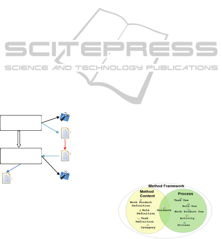
Figure 1: Two activities of a lift development process.
Semantically, the artefacts (a) and (b) in this
process present the same design model of system but
represented in different languages: one is modelled
in UML and the other is in annotated C. We can say
(a) is equivalent to (b).
Our first remark is that if the equivalence relation
(1) between these two artefacts is modelled, it will
be possible to detect the point of tool integration
from the process model. However, currently, SPEM
2.0 does not allow modelling the relation (1).
Secondly, if we can distinguish the abstract
artefacts of a domain (e.g. system model) from their
representations in different technical spaces, we can
deduce the equivalence relation between two
technique-dependent artefacts presenting the same
domain artefact. For example, at the technical space
level we have artefact (a) in MoPCom UML and (b)
in BlueBee C. These artefacts both have a relation to
their domain artefact system design model; thus the
relation between (a) and (b) can be deduced.
We think that a reasonable approach to enhance
the process modelling and facilitate the tool
integration issue could be refining the modelling
language and using a semantics network to store
process elements and their inter-relations at different
levels. The next section present in details these
propositions.
3 COMBINING PROCESS
EDITOR & ONTOLOGY
This section is divided into three parts: the first one
recalls some basic concepts of SPEM; the second
resumes iSPEM, our extension of SPEM 2.0; the
third one presents the use of a process ontology to
reason about semantics of process elements’ inter-
relations.
3.1 SPEM 2.0
A Process in SPEM is composed of several
Activities; an Activity is described by a set of linked
Tasks, WorkProducts and Roles. A Role can
perform a Task; a WorkProduct can be the input or
output of a Task. A WorkProduct can be managed
by a Tool and a Task can use a Tool.
To support process reuse, SPEM 2.0 seperates
the definition of process elements from their uses
(Figure 2).
Figure 2: SPEM 2.0 process elements in two viewpoints.
Design System
by MoPCoM
Generate System
by BlueBee
Rhapsody UML
BlueBee
(a) System model
in UML
(b) System model
in BlueBee
System C Code
(1)
MODELSWARD2015-3rdInternationalConferenceonModel-DrivenEngineeringandSoftwareDevelopment
566
Method Content regroups reusable element’s
definitions (Task Definition, Work Product
Definition and Role Definition) which can be
instantiated several times as element’s use (Task
Use, Work Product Use and Role Use) in one or
many concrete processes
3.2 Multi-level Process Elements
We propose iSPEM based on our previous works on
process modelling (Tran et al., 2006; Koudri, 2010;
Zhang et al., 2012). The two key points of iSPEM
are: (1) adding into SPEM new concepts describing
tool-related elements to prepare tool integration; (2)
distinguishing reusable method content elements at
different abstraction levels to allow a better context-
based reusability and to make semantic relationships
emerge.
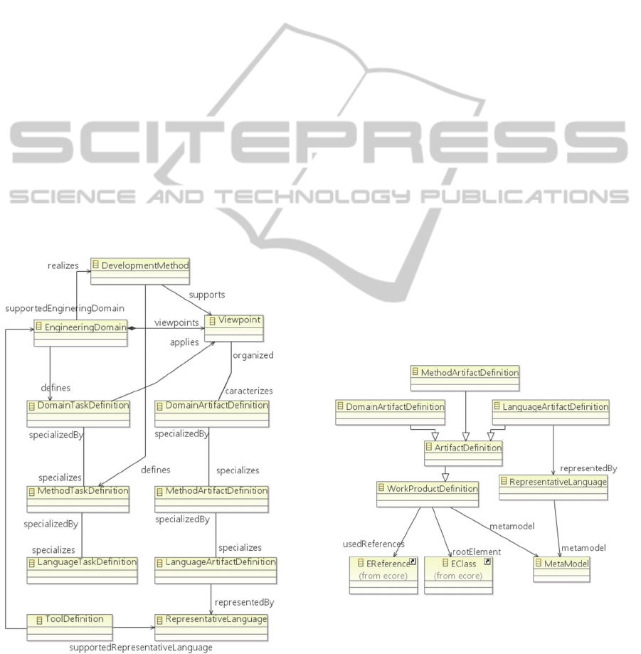
iSPEM extends the SPEM 2.0’s package
ProcessWithMethods. Three abstraction levels are
defined: Engineering Domain, Development
Method, and Language. The Method Content
elements, including Task Definition and Work
Product Definition, are hence refined at each of
these three levels (Figure 3).
Figure 3: Abstraction of Method Content in iSPEM.
Engineering Domain: this level represents the
working context where the method content
elements are defined. Thus, each element at this
level has a consensus semantic in a given
engineering domain, independently with any
development method or modelling language. The
Viewpoint concept is added to allow organizing
the activities into principal works.
Development Method: this level represents the
elements defined in a concrete development
method which are used to realize one or some
Viewpoint. Therefore, an Engineering Domain
element can be realized by various Method
elements.
Representation Language: this level
characterizes method content elements according
to the modelling language used to represent
them. Once again, several elements at this level
can have the relation of the same element on the
higher level.
Equivalence Relation: 2 elements at the same
abstraction level are equivalent if they are in
relation with the same element in a higher
abstraction level. For example, two different
Method elements realizing the same Domain
element are equivalent; two language elements
representing the same Method element are
equivalent.
The Work Product Definition is refined to describe
the inside structure of models. Concretely:
The concept Meta model is introduced and linked
to other Work Product Definition element at
different abstraction levels as shown in Figure 4.
Figure 4: Work Product Definitions in iSPEM.
The meta-meta-model Ecore is reused to
construct the structure of ArtifactDefinitions or to
manage meta-models. The relationship between
the Ecore’s elements with iSPEM elements are
presented in Figure 5.
UsingProcessOntologyTogetherwithProcessEditor-ToFacilitateToolIntegration
567
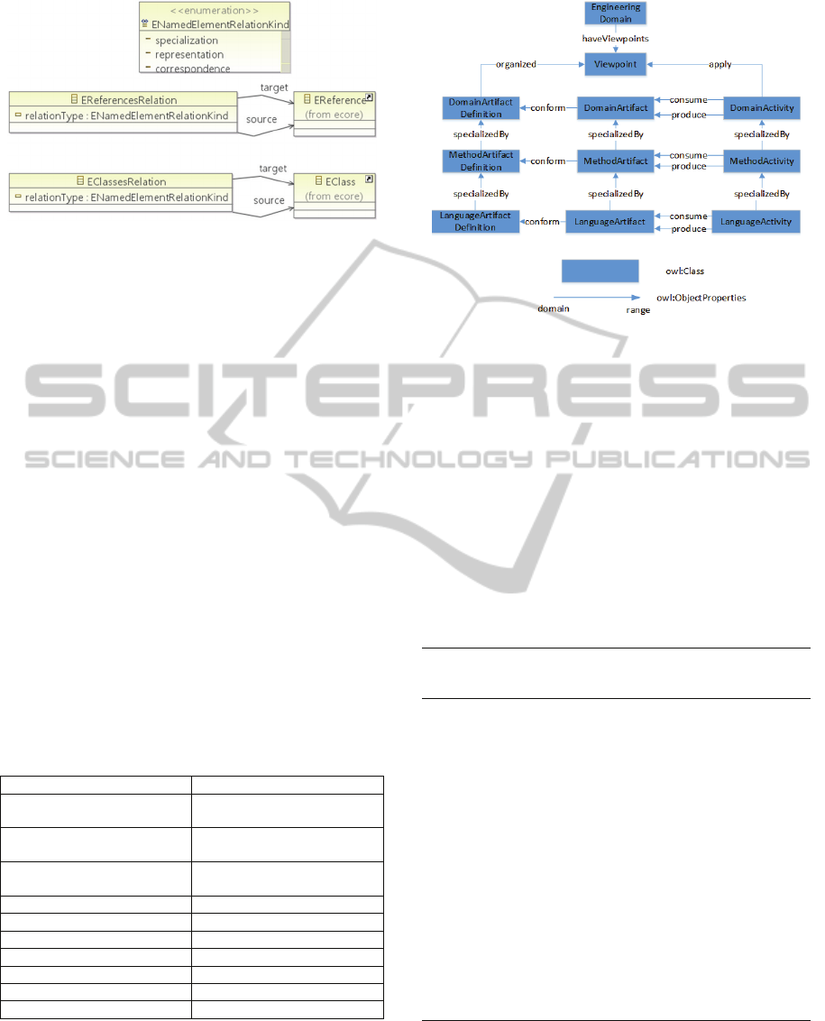
Figure 5: Relationship between meta-models.
We also refine the concepts Process and Activity
and associate them with the Engineering Domain
level. The new element ArtifactTransformation is
used to model the tool integration points where a
model transformation is needed to enable the
exchange of artefacts between two tasks.
3.3 Reusable Process Ontology
3.3.1 Ontology Organisation
We don’t use a simple database to store reusable
process elements captured from different processes
but an ontology in order to enable reasoning about
process elements. In this work, we structure and fill
the ontology with iSPEM concepts, but it can be
adapted to store elements from other processes. Our
Reusable Process Ontology is represented in OWL
(OMG, 2009). In OWL, the class are presented by
owl:Class and the class’s properties are presented by
owl:ObjectProperties or owl:DataProperties.
Table 1: Mapping between the owl class of Reusable
Process Ontology and EClass of iSPEM.
Reusable Process Ontology iSPEM
(Domain/Method/Language)
Process Activity
(Domain/Method/Language)
Task Definition
(Domain/Method/Language)
Artifact
(Domain/Method/Language)
Artifact
(Domain/Method/Language)
Artifact Definition
(Domain/Method/Language)
Artifact Definition
Role Role Definition
Tool Tool Definition
Engineering Domain Engineering Domain
Viewpoint Viewpoint
Development Method Development Method
Representation Language Representation Language
Meta Model Meta Model
An extract of our ontology which represents the
relation between these owl classes is also shown in
Figure 6.
Figure 6: An extract of Process Ontology.
The existing Ecore ontology in OWL from
ModelCVS which has a full mapping with MOF
version is also reused. The other concepts related the
refinement of Work Product Definition which is
introduced earlier such as EReferencesRelation,
EclassesRelation are thus defined on the ontology.
3.3.2 Generation of Transformation Rules
for a Tool Integration Point
We develop two algorithms for reasoning about the
process ontology. Algorithm 1 identifies the tool
integration points in a process model:
Algorithm 1: Identify Artefacts to be transformed at a
tool integration point.
Input: List of artefacts at the Language level – artifactList
Output: List of artefacts to be transformed –
artifactTransformationList
1. For each pair of (artifact1, artifact2)
1.1. If artifact1 is created before artifact2
and artifact1.toolArtifactDefinition
!=artifact2.toolArtifactDefinition
1.1.1.Then if artifact1.domainArtifactDefinition
== artifact2.domainArtifactDefinition
Then var artifactTransformation :
new ArtifactTransformation (artifact1, artifact2)
artifactTransformationList.add(artifactTransformation)
End If (1.1.1)
1.2 End if (1.1)
2. End For (1)
3. Return artifactTransformationList;
Algorithm 2 generates the needed mapping rules
between two equivalent artefacts at an identified tool
integration point.
The idea is from the actual abstraction level of a
MODELSWARD2015-3rdInternationalConferenceonModel-DrivenEngineeringandSoftwareDevelopment
568
source artefact; go up one level of the ontological
relationship specializedBy to find out its upper-class.
From the found upper-classe we can go down again
one level to find out an equivalence of our source
artefact but represented in another technical space.
Algorithme 2: Generate Mappings between two meta-
models of the artefacts in the transformation list identified
by Algorithm 1.
Input : Source Meta-model MM-in, Target Meta-model
MM-out
Output: List of mappings between elements of MM-in and
MM-out – mappingList
1. For each élément element1 de MM-in
1.1 For each élément element2 de MM-out
1.1.1 If element1.specializedBy ==
element2.specializedBy
1.1.2 Then
1.1.2.1 var representation1 : element1.representedBy
var representation2 : element2.representebBy
1.1.2.2 mappingList.addMapping(representation1,
representation2)
1.1.3 End If
1.2 End for
2. End For
3. Return mappingList
The above algorithms are formalized in SWRL
(Horrocks et al., 2004) and reasonable by ontologies
reasoners.
4 ISPEM PROCESS EDITOR
This section presents first the implementation of the
iSPEM process editor and then a case-study used to
validate the system.
4.1 Implementation of iSPEM System
Figure
7
:
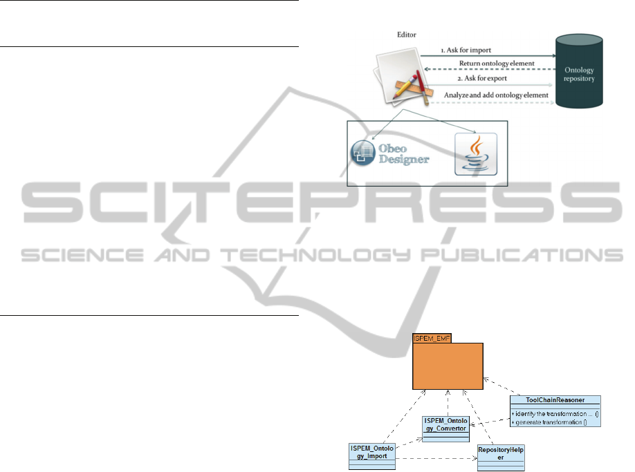
Figure 7 shows the structure of the iSPEM
system which is composed of two components: a
process editor for process modelling and an ontology to
store reusable process elements.
Process Editor: the iSPEM editor is an extension of
the SPEM-Designer editor of Obeo (Obeo, 2012)
that have basic process modeling functionalities
implemented with Obeo Designer software. Then we
develop the editor’s additional functionalities in Java
to enable:
A EMF-based framework for creating an
manipulating iSPEM models.
Modeling process by reusing relevantly the
Method Contents in a specific context.
Connect to the ontology repository and importing
the Method Contents from the Reusable Process
Ontology repository into iSPEM models.
Identifying automatically the tools integration
points.
Generating the textual transformation rules for
each the tools integration point.
Figure 7: Structure of iSPEM process editor.
OWLAPI (OWL API ) is used for manipulate the
ontology and Pellet reasoner (Pellet) helps us on
reasoning the rules implementing the Algorithms 1
and 2 (c.f. Section 3.3.2).
Figure 8 presents the Java classes developed for
iSPEM enhanced functionalities.
Figure 8: iSPEM’s Java classes.
Process Ontology: First, we used Protégé (Protégé
Ontology Editor) to define the following ontologies :
Ontology of meta models based on the existing
ontology ModelCVS project and added with
additional properties such specializedBy,
representedBy, etc.
Process Ontology supporting generally process
modeling specially tool integration needs.
In the first time, we enrich manually these
ontologies with the data come from our case-studies.
For storing ontologies, we use OWLIM-Lite
(OWLIM-Lite)0, a RDF database management
system. The algorithms presented in Section 3.3.2
are implemented as SWRL rules.
UsingProcessOntologyTogetherwithProcessEditor-ToFacilitateToolIntegration
569

4.2 Case-study
We validate iSPEM Editor with the lift development
example presented in Section 1 (c.f. Figure 1), this time
with details on each activity’s tasks as shown in Figure
9.
Figure 9: Lift Development Process’s activities in Design
& Implementation Engineering Domain.
This process fragment contains two activities in
the Design & Implementation Domain: Design
System for producing System Model and Generate
System for generating the System Code for a given
hardware architecture. By using specific methods
and languages to implement the Lift Development
Process, these domain-dependent elements can be
specialized into method-dependent elements which,
in their turn, can be also specialized into language-
dependent elements. Here, the process in Figure 9 is
realized with the development methods and
languages MoPCoM in UML and BlueBee in C.
A system model designed by MoPCoM
methodology is split up into 3 sub-models: a
functional specification of the system, a
representation of the platform and an allocation of
the functional element onto the platform. Thus the
MoPCom method refines the Design System
activities into three tasks: MoPCom Logical
Architecture Definition, MoPCom Platform
Definition and MoPCom Allocation Definition) to
produce respectively Architecture Model,
Application Model and Mapping Model which
together compose the System Model in UML.
The Generate System activity is realized with the
Bluebee toolchain. Concretely, the task System
Generation with Bluebee takes a Bluebee
comprehensible System Model to generate the
System Code for the target architecture. A Bluebee
comprehensible model is composed of an annotated
C code, the pragmas that define the C function
mapping onto the computing elements and a XML
file that describes features about the target
architecture.
While MoPCoM allows describing both
functional and hardware elements in UML elements,
Bluebee makes a distinction with hardware elements
represented in XML and functional ones represented
in C. So we need to transform the System Model in
UML into the format required by Bluebee (relation
(1)). For instance, the platform model in MoPCom
actually corresponds to the architecture specification
by XML in BlueBee,
In this case study, we assume that the necessary
reusable process elements are already stored in the
Process Ontology. Concretely, first we created the
ontology in Protégé and added into it the Design and
Implementation Domain process package containing
activities, tasks, artefact definitions, artefacts and
also the related metamodels of the domain. Then the
more specialized packages including MoPCoM
method package, MoPCoM with UML lanuguage
package, MoPCoM with SysML language package,
Bluebee method package, Bluebee with C language
package are added. Figure 10 and Figure 11 show
the process elements of the D&I Domain
stored in
the Process Ontology at three levels: Domain,
Method and Language and the specialization
relations between them.
Now we can use iSPEM to model the process in
Figure 9. To do so we import the Process Ontology
into the iSPEM editor and create corresponding
iSPEM method content elements. These elements
then are used to create the lift development process.
Then we use the functionality Identify
Transformation Points, which implements the
Algorithm 1 in Section 3.3.2, to detect the tool
integration points. The complete model is shown in
Figure 13.
The generation of transformation rules for each
tool integration point is realized by using the
Algorithm 2 in Section 3.3.2. For example, Figure
12 shows the mappings deduced between the artefact
LogicalArchitechPackage in MoPCom (represented
as an UML package) and the artefact SourceCode in
BlueBee (represented by a C program) thanks to the
links from these artefacts to the common artefact
Application Model Definition at the Domain Level.
Similarly, we can deduce that the Platform
Model in MoPCom (an UML package) actually
corresponds to the Organization Specification (XML
code) in BlueBee. Figure 14 shows the generated
transformation rules based on this mappings.
MopCom
LogicalArchitecture
Definition
MopCom
Platform
Definition
Design System
with MoPCoM
Generate System
with Bluebee
Rhapsody
UML
BlueBee
System Model
in UML
System Model
in BlueBee
System Code
in C
(1)
MopCom
Allocation
Definition
BlueBee
System Generation
MODELSWARD2015-3rdInternationalConferenceonModel-DrivenEngineeringandSoftwareDevelopment
570
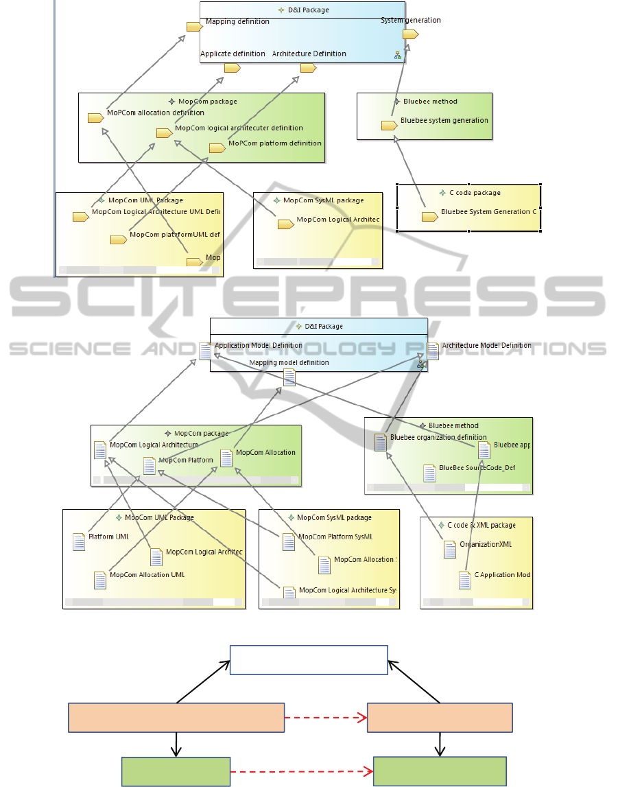
Figure 10: Specialization of Tasks in D&I Domain.
Figure 11: Specialization of Artefacts in D&I Domain.
Figure 12: Mappings deduced from the ontology.
DI:StructuredComponent
MoPCoM:LogicalArchitecturePkg BlueBee:SourceCode
UML:Package
Ccode:SourceCode
specializedBy
specializedBy
representedBy representedBy
transformedInto
corresponds
UsingProcessOntologyTogetherwithProcessEditor-ToFacilitateToolIntegration
571
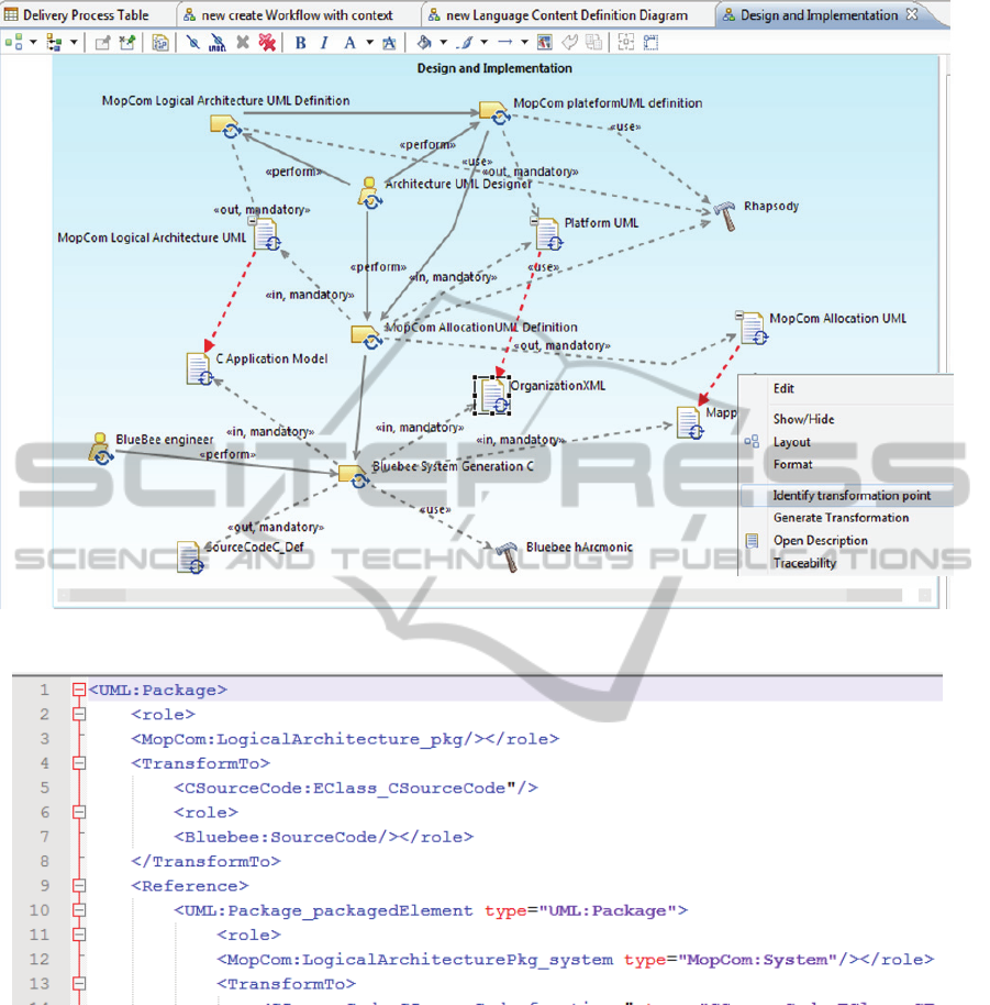
Figure 13: Process Modeled in iSPEM Editor with tool integration points identified.
Figure 14: Generated Transformation rule.
5 CONCLUSIONS
This paper presents a combination of ontology and
process modelling technique to facilitate tool
integration. Lifting the process elements up to
ontology space enhances the capacity of process
editors in reasoning about the semantical relation
between process assets accumulated from different
process and thus could be more helpful for
collaborative processes.
Some works also use SPEM to describe the
information on tool integration as in (Biehl and
Törngren, 2012) which uses SPEM process models
for creating the skeleton of a tool chain. This work
identifies a number of relationship patterns between
the development process and its supporting tool
chain and show how the patterns can be used for
constructing a tool chain which is aligned with the
process. But they don’t use ontology technique.
Some works combine ontology with process
techniques as (Líška, 2010), (Rodríguez et al., 2010)
and (Valiente et al., 2012). The work in (Valiente et
MODELSWARD2015-3rdInternationalConferenceonModel-DrivenEngineeringandSoftwareDevelopment
572

al., 2012) describes an approach to integrate Sofware
Process and IT service management ontologies in
order to ease the integration of business information
early in the software development lifecycle. In
(Rodríguez et al., 2010) the authors show how to
translate a SPEM process model to OWL ontologies
which in turn can be used for checking constrains
defined in the processes using SWRL rules.
Similarly, the work in (Líška, 2010) presents a
SPEM Ontology which constitutes a semantic
notation that provides concepts for knowledge based
software process engineering. However the
mentioned works don’t deal with the tool integration
issue.
Our main contribution here is the use of ontology
to deduce automatically the transformation rules
between artefacts concerned in a tool integration
point.
Further work needs to be done to develop more
precise mapping. Another question would be to
investigate is the capture of process assets from
diverse process models to enrich automatically the
process ontology.
REFERENCES
Biehl, M., Törngren, M., 2012. Constructing Tool Chains
Based on SPEM Process Models. In ICSEA’12, 7
th
International Conference on Software Engineering
Advances.
Bluebee, http://www.bluebeetech.com.
European iFEST project: Industrial Framework for
Embedded Systems Tools. http://www.artemis-
ifest.eu/home.
Horrocks, I., Patel-Schneider, P., F., Boley, H., Tabet, T.,
Grosof, B., Dean, M.. 2004. SWRL: A Semantic Web
Rule Language, Combining OWL and RuleML.
http://www.w3.org/Submission/SWRL.
Líška, M. 2010. Extending and Utilizing the Software and
Systems Process Engineering Metamodel with
Ontology. Information Sciences and Technologies,
Bulletin of the ACM Slovakia, Vol. 2, No. 2, pp. 8-15.
Koudri, A., 2010, MODAL: a SPEM extension to improve
co-design process models. New Modeling Concepts for
Today’s Software, pp. 248-259.
Obeo. 2012. SPEM Designer. Available at:
http://marketplace.obeonetwork.com/module/spem.
Object Management Group. 2009. Ontology Definition
Meta-Model 1.0.
Object Management Group. 2008. Software and Systems
Process Engineering Meta-Model 2.0.
OWLIM-Lite - OWLIM50 - Ontotext Wiki.” (Online).
Available:http://owlim.ontotext.com/display/OWLIM
v50/OWLIM-Lite.
OWL API. Available: http://owlapi.sourceforge.net/.
Pellet: OWL 2 Reasoner for Java. Available:
http://clarkparsia.com/pellet/.
Protégé Ontology Editor and Knowledge Acquisition
System. Available: http://protege.stanford.edu/.
Ngo, C. D., 2012. Master thesis at Ensta-Bretagne.
Rodríguez, D., García, E., Sánchez, S. and Rodríguez-
Solano Nuzzi, C. 2010. Defining Software Process
Model Constraints With Rules Using Owl And Swrl.
International Journal of Software Engineering and
Knowledge Engineering 2010 20:04, 533-548.
Tran, H. N., Coulette, B., Dong, B. T. 2006. A UML based
process meta-model integrating a rigorous process
patterns definition. In Proceedings of the 7th
International Conference on Product Focused
Software Process Improvement (PROFES‘06),
Amsterdam.
Valiente, M.-C., Garcia-Barriocanal, E., Sicilia, M.-A.,
2012. Applying Ontology-Based Models for
Supporting Integrated Software Development and IT
Service Management Processes. IEEE Transactions on
Systems, Man, and Cybernetics, Part C: Applications
and Reviews, vol.42, no.1, pp.61,74.
Vidal, J.; de Lamotte, F.; Gogniat, G.; Soulard, P.; Diguet,
J.-P. 2009. "A co-design approach for embedded
system modeling and code generation with UML and
MARTE," Design, Automation & Test in Europe
Conference & Exhibition, 2009 (DATE '09).
Wasserman, A. I., 1990. Tool integration in software
engineering environments. Lecture Notes in Computer
Science Volume 467, pp. 137-149.
Zhang, W., Leilde, V., Moller-Pedersen, B. Champeau, J.
and Guychard, C., 2012. Towards tool integration
through artifacts and roles. In Proceedings of 19
th
Asia-Pacific Software Engineering Conference
(APSEC’12).
UsingProcessOntologyTogetherwithProcessEditor-ToFacilitateToolIntegration
573
