
Cones-assembled Grating for Long-range Fiber-optic Linear
Displacement Sensor
Zeina El Rawashdeh, Philippe Revel, Christine Prelle and Frédéric Lamarque
Laboratoire Roberval UMR 7337, Université de Technologie de Compiègne, 60200, Compiègne, France
Keywords: Fiber-optic Sensor, Geometric Modelling, Grating Geometric Design, Diamond Tool Fabrication,
Long-range Displacement.
Abstract: This paper presents the initial design of a new fiber-optic displacement sensor; it is used to measure the
linear displacement of an actuator performing a helical movement. This sensor consists of a set of
assembled cones, which constitute a reflective grating, and two fiber-optic probes. It is characterised by its
ability to measure the displacement along a millimetric range, with a high sub-micrometric resolution. In
this work, the geometric model of the sensor is presented as well in terms of single probe response in front
of a curved reflective surface as in terms of grating shape which authorizes the measurement principle. This
grating design makes the displacement measurement possible due to the overlap of the two probes simulated
output signals. The single probe measurement in front of a curved reflective surface demonstrates a good
agreement with simulation results. A prototype of the cones-assembled grating has been fabricated using a
high precision turning machine and a single-crystal diamond tool on an aluminium alloy; the geometric
parameters of the fabricated grating were evaluated with the help of a Nanofocus
TM
µscan optical
profilometer. The agreement between the simulated geometric parameters and the real parameters is very
good.
1 INTRODUCTION
The need of miniature sensors is becoming essential
in modern sciences. Development of micro sensors
with high sensitivity, high resolution and high
dynamic range dominates the research field for
different commercial applications (Mukherjee,
2012). Among the different parameters in numerous
applications, is the displacement to be measured
with high accuracy, and wide dynamic range.
High resolution and long range contactless
displacement sensors are integrated in mechanical
systems, where highly precise performances are
required. (Fan, 2007) presented the design of a
measurement system, consisting of a mini LDGI
(linear diffraction grating interferometer) and a
focus probe, these two sensors are integrated into the
spindle system of a micro/nano-CMM (coordinate
measuring machine). The system accuracy is 30 nm
for a 10 mm displacement of the spindle.
Fiber-optic technology is chosen for the sensor
design because it can achieve contactless
measurements within a miniature probe size.
A particular interest in recent studies is to design
miniature fiber-optic displacement sensors with high
relative accuracy (nanometric resolution /millimetric
range; ratio ~ 10
-6
).
The study developed by (Lee, 2012) presented
the design of a fiber-optic displacement sensor with
large measurement range; it is composed of a
transmissive grating panel, a reflection mirror, and
two optical fibers as a transceiver. The measured
bidirectional movement demonstrated a peak to peak
accuracy of 10.5 µm, high linearity, resolution of 3.1
µm at the full bandwidth, signal-to-noise ratio of
27.7 during a movement of 16004 µm.
To satisfy the requirements of the target
application for the sensor, which is the on-line depth
measurement for drilled-holes, the surface of the
sensor grating must be axis-symmetrical, and
consequently the surface has to be curved (convex).
(Zhao, 2000) presented a novel fiber-optic sensor for
small internal curved surface measurement. The
measurement principle is based on beam reflection,
and it gives high vertical resolution of 0.1 µm with 8
µm measuring error.
(Patil, 2011) developed a generalised
mathematical model able to do the simulation of any
147
El Rawashdeh Z., Revel P., Prelle C. and Lamarque F..
Cones-assembled Grating for Long-range Fiber-optic Linear Displacement Sensor.
DOI: 10.5220/0005432001470155
In Proceedings of the 3rd International Conference on Photonics, Optics and Laser Technology (OSENS-2015), pages 147-155
ISBN: 978-989-758-092-5
Copyright
c
2015 SCITEPRESS (Science and Technology Publications, Lda.)
configurations of fiber-optic sensors. It is based on
ray tracing approach and different matrix
transformations such as translational, reflection or
rotational are used. In addition, (Bingshi, 2008)
studied the influence of the fiber-optic displacement
sensor parameters on its performances, focusing
on geometrical parameters such as the numerical
aperture, the radius of fiber core, the lateral
separation of transmitting and receiving fibers,
the angle between the two fibers and the
reflector curvature radius. (Utou, 2006) have
carried out various experiments in order to verify the
effects of various parameters on the accuracy
measurement of a fiber-optic displacement sensor,
for example: orientation between sensor tip and
target surface, i.e. angularity, the effect of varying
reflectivity of targets’ surfaces, the effect of
various transparent material thickness over the
target reflective surface and the displacement of a
surface in an arc-path away from the stationary
tip of a sensor. It was found out that the higher the
values of transparent material thickness, the lower
the sensitivity values obtained from the fiber-optic
sensor probe. The result from the experiment of the
angle variation between target and sensor has shown
that the sensor sensitivity reduces for angles higher
than 20°.
Finally, (Gaikwad, 2012) developed a novel
intensity-modulated fiber optic displacement sensor
with a convex reflector, in which the sensing
structure was described, and the derivations of
geometric and Gaussian mathematical models were
demonstrated.
This paper introduces first a geometrical model
of a convex surface reflector, together with its
experimental validation. Then, the modelling of the
long-range measurement is done which gives the
geometrical parameter of a set of assembled cones
which constitute an axi-symetrical grating. The
grating have been fabricated with a high precision
turning machine together with a single-crystal
diamond tool, in order to obtain high geometric
precisions and a good surface quality (R>95%,
polished-mirror surface).
These fabricated cones have been geometrically
characterised for future use of the sensor, where high
performances regarding its sensitivity, measurement
range and resolution are required for online depth
measurement while machining.
2 SENSOR PRINCIPLE
The sensor consists of two fiber-optic probes
associated to a high reflective surface. Each probe
has one emission fiber and four reception fibers.
The sensor performances when it is associated to a
planar surface have been already analysed (Alayli,
1998, Girão 2001). When translating the flat mirror
perpendicularly to the probe axis, the sensor
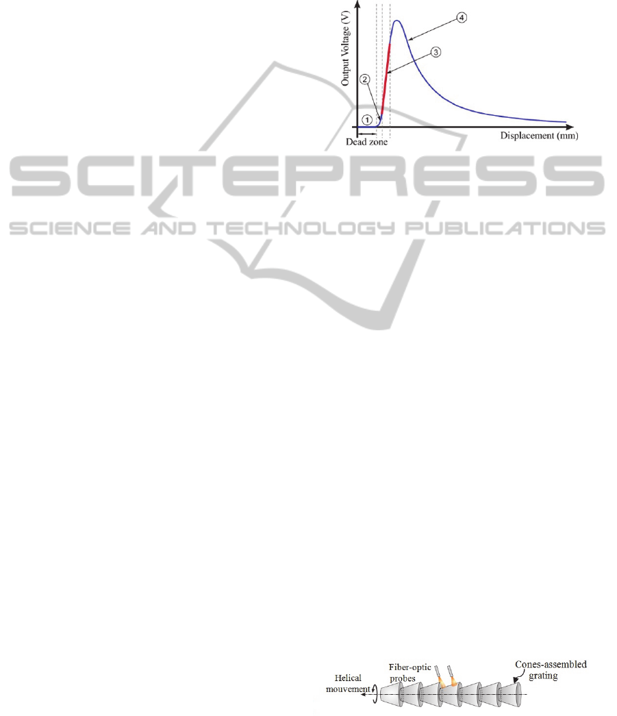
response curve is obtained (Figure 1).
Figure 1: Response curve of the fiber-optic displacement
sensor.
The preferred working zone of the sensor is zone (3)
because of its linearity and high sensitivity.
However, the measurement range of this zone is too
small (<200 µm). So, in order to increase the linear
zone, the displacement direction of the flat mirror is
different from the normal vector orientation of its
surface resulting in the multiplication of the nominal
range value by (sin ε)
-1
factor where ε is the
inclination angle related to the grating axis. By
repeating the tilting mirror configuration, a grating is
obtained. For an inclination angle ε of several
degrees, the sensor resolution can be reached to 15
nm and the measurement range can be increased to
several millimeters as a function of the grating steps
number. It is possible to do long-range
measurements if the non-linear signal during the
transition between two consecutive steps is
avoided. To do so, two probes are used, to ensure a
continuous displacement measurement over the
long-range by alternately switching between the
probes in order to avoid strong non-linearity due to
the illumination of two grating steps at the same
time. A sensor prototype was successfully modelled,
designed and tested (Prelle, 2006).
The objective of the current work is to develop a
sensor able to measure precisely the linear
displacement of an actuator performing a helical
movement. For this new application, the sensor
Figure 2: Measurement principle with a 3D grating.
PHOTOPTICS2015-InternationalConferenceonPhotonics,OpticsandLaserTechnology
148

reflective grating has to have a 3D shape in order to
provide a valid measurement even if the sensor
rotates along its axis of symmetry, as shown in the
figure 2.
3 GEOMETRIC MODEL OF THE
REFLECTIVE SURFACE
3.1 Convex Surface Modelling
The influence of the curved reflector on the sensor
performances was modelled. The reflective grating
of the sensor is a set of assembled cones, which
implies that the sensor reflector surface is convex.
This property will modify the sensor performances
as compared to the previous existing sensor with
grating composed of an assembly of flat mirrors
(Prelle, 2006, Khiat 2010). In order to observe the
influence of the convex surface on the sensor
performances, different geometric parameters were
considered. These parameters are shown in Table 1
and figure 3.
Table1: Geometric model parameters.
Symbol
Definition
Ø The probe diameter (mm)
R
c
Radius of curvature (mm)
M Tangential point
n
M
Normal vector to tangent
d
0
Initial distance between the reflector
and the probe (mm)
α The incidence angle
The angle between n
M
and the
symmetrical axis of the probe
e
The spacing between the emission
fiber and the reception fiber
Δ
The spacing between the normal
vector of the flat surface and the
reflected beam from the curved
surface intercepted by the sensor
The aim of this theoretical model is to analyse the
sensor performances when it is associated to a
convex reflector, and compare these performances to
a planar reflector. For that, the response curve of the
sensor was generated in the two cases (Flat surface
and convex surface), by detecting the light intensity
of the sensor as a function of the displacement (d
0
)
and the radius of curvature (R
c
).
In the model two conditions were taken into
account to ensure that the light is detected by the
sensor.
(a)
(b)
Figure 3: Schematic diagram of the reflected light model:
(a) Flat mirror, (b) convex mirror.
These conditions are illustrated in the following
equations:
α < β – 2 × δ (1)
R
emission
+ e < X
0
+∆ < R
emission
+ e + D
reception
(2)
Where β = arcsin(0.46), α and δ are defined in Table
1, R
emission
is the radius of the emission fiber, and
D
reception
is the diameter of the reception fiber.
The variables δ and ∆ are calculated geometrically
for each point (X
0
, Y
0
).
Figure 4 represents the results of several radii of
curvature (R
c
) as a function of the displacement (d
0
).
Cones-assembledGratingforLong-rangeFiber-opticLinearDisplacementSensor
149
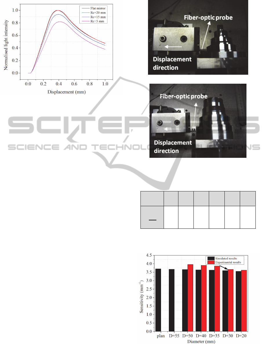
Figure 4: Response curves for several radii of curvature.
The flat mirror configuration is used as the
reference. It is clear that the higher the radius of
curvature is, better will be the normalised light
intensity detected in the linear part of the curve, in
consequence, better will be the sensor performance.
For R
c
= 15 mm, the signal light intensity reduces
sharply.
Table 2 represents the loss in sensitivity ratio
(Att) due to the convex form of the reflector, as a
function of different radii of curvature, where:
Att : The loss in sensitivity ratio
S
: The linear sensitivity of a curved
reflector (mm
-1
)
S
∞
: The linear sensitivity of a planar
reflector
3.2 Experimental Validation of the
Convex Surface Modelling
The geometric model previously described has been
validated experimentally by fabricating two pieces
of cylinders with different diameters: Piece (A) with
small diameters (40, 30, 20, 10 mm) and piece (B)
with large diameters (55, 50, 40, 35 mm). These two
pieces have been fabricated with a single crystal
diamond tool on a high precision turning machine
whose characteristics and performances are
described in section 5.
For each cylinder in the two pieces, the
calibration curve of the sensor has been obtained by
moving the sensor away from the cylinder reflecting
surface. The linear sensitivity has been calculated
for each curve, with a linearity criterion of 1 %.
Figure 5 illustrates the experimental set-up used; it
consists of the two reflecting pieces together with a
fiber – optic probe.
(A): small diameter piece
(B): large diameter piece
Figure 5: Experimental set-up.
Table 2: Loss in sensitivity
R
c
(mm)
1 5 10 15 20
∞
Att
S
S
∞
0.7 0.74 0.8 0.91 0.98 1
The experimental sensitivities (zone 3 of figure 1)
have been compared to the theoretical sensitivities in
Figure 6: Influence of the diameter of the reflective
convex surface on the sensor sensitivity.
PHOTOPTICS2015-InternationalConferenceonPhotonics,OpticsandLaserTechnology
150
order to test the precision of the geometric model
(Figure 6).
The previous figure illustrates the influence of
the cylinder diameter on the linear sensitivity of the
sensor (simulated and experimental). It reduces as
the cylinder diameter decreases.
This experiment validates the geometric model and
shows that it is preferred to have a diameter higher
than 35 mm for applications requiring high
sensitivity.
For the mentioned reasons, and to guarantee a
good performance of the sensor, the cones-
assembled grating has been fabricated from a 50 mm
diameter cylinder.
4 GRATING GEOMETRICAL
DESIGN
A geometrical model was developed to simulate the
functioning of the long-range displacement sensor.
As a result, the optimal dimensions for each step of
the grating are provided. These dimensions ensure
the measurement continuity over a millimetric range
with a sub-micrometric resolution. This geometrical
model takes into account the following two
conditions:
1. The distance between the probe and the grating
step has to be in the linear zone (zone 3 of
figure 1).
2. The overlap between two successive signals is
fixed at 30 µm to avoid the linear measurement
discontinuity during the steps transition.
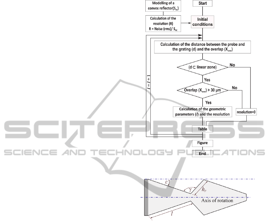
The grating geometrical model is based on the
algorithm shown in figure 7.
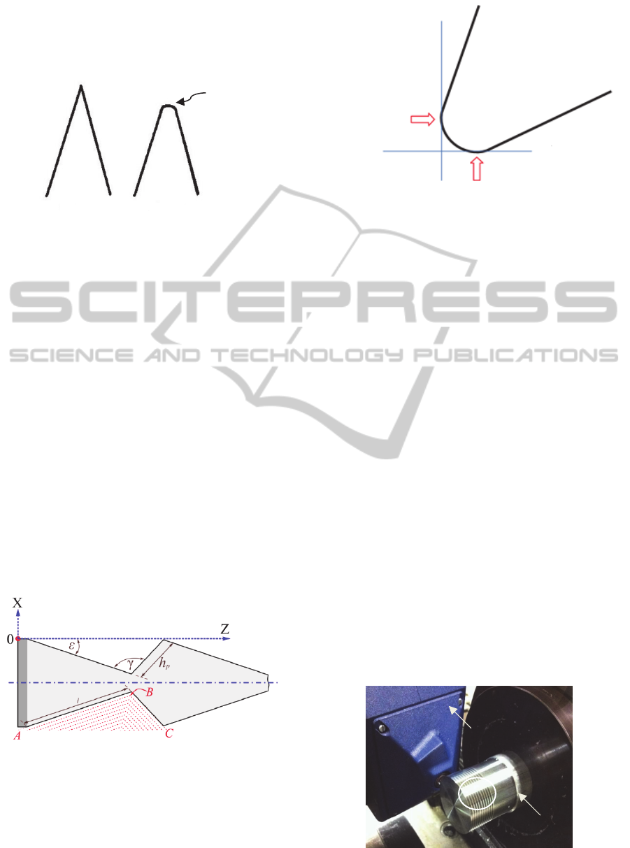
Figure 8 shows the geometric parameters
considered for a step in the cones-assembled grating,
where:
l: The step length (µm)
h
p
: The step height (µm)
ε:The step angle (°)
γ: the angle at the bottom of the step (°)
The model optimizes the dimensions to get the best
limit of resolution which depends on the value of ε.
The more ε is, the smallest will be the limit of
resolution.
Figure 8 shows the successive
algorithm sequences used to simulate the
functioning of the measurement principle. The
geometric model of the convex surface explained
above leads to the best limit of resolution of a single
fiber-optic probe used as a simple displacement
sensor.
Figure 7: Algorithm of the geometrical model.
Figure 8: Geometrical parameters of the cones-assembled
grating.
The algorithm figured out the values of each
geometric parameter:
The step length (l) is 1541 µm
The segment (h
p
) is 253 µm
The angle (γ) is 130°
The step angle ε is 7.17°
The theoretical limit of resolution is 24 nm with an
overlap between the two signals of 30 µm.
Figure 9 shows the theoretical displacements
calculated with Matlab software, where:
Theoretical axial position (µm): The position of
the sensor in the classical case (without
inclination)
Theoretical lateral position (µm): The position
of the sensor in the lateral case (with
inclination)
It is clear that the lateral displacement range
Cones-assembledGratingforLong-rangeFiber-opticLinearDisplacementSensor
151
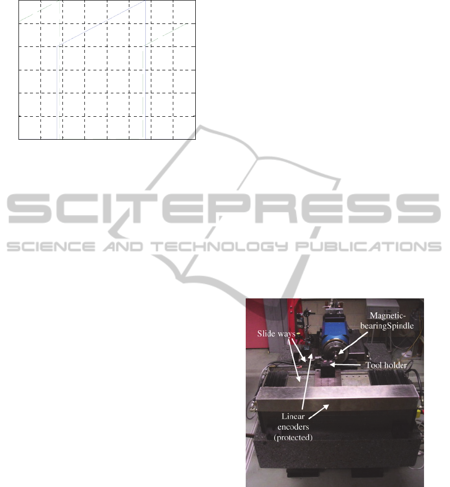
Figure 9: Theoretical axial position (µm) vs. theoretical
lateral position (µm).
(801.0 µm) is higher than the axial one (100.1µm),
by a factor of sin 7.17°.
5 CONICAL GRATING
FABRICATION
After the geometrical model phase, the fabrication
technique has to be taken into account, and that
includes the performances of the turning machine, as
well as the fabricating tool whose geometrical
design, particularly, its radius of curvature
influences the fabrication procedure and its final
product.
A machining program has been used, in which
all these constraints have been taken into
consideration.
5.1 Fabricating Elements
Characteristics
In the case of 3D axis – symmetrical pieces, the high
precision rotating spindle coupled with single crystal
diamond tool provide high geometrical precisions as
well as good surface qualities. That is important for
the sensor based on cones-assembled grating, where
the light reflection influences the sensor sensitivity
and range.
The machine used for the fabrication technique is
a high precision turning machine (Figure 10).
The machine is a prototype lathe with T slide
architecture. On the Z-axis a magnetic bearing
spindle is fixed, and on the X-axis is fixed the tool
holder. The two hydrostatic slides (X and Z) are
fixed on a 1.5 ton granite block; this block is
supported by a high frequency vibration-filtration
system.
The hydrostatic bearings minimise the friction
forces to ensure a high rigidity as well as a straight
tool trajectory. For each axis, the straightness error
is 0.3 µm for a total displacement of 100 mm.
The two slides are actuated with the help of two
linear motors; the displacement is measured by an
optical encoder with a 4 nm limit of resolution.
The two motors are controlled numerically with
the help of PMAC card.
On the Z-axis, a high precision rotating spindle is
fixed together with magnetic bearings in order to
avoid friction loss and to ensure the right trajectory
during rotation.
This machine proved highly geometrical
precisions regarding the dimensions of the fabricated
pieces as well as high surface qualities (Gautier,
2008).
In order to obtain high surface roughness less
than 15 nm, it is preferred to use a single – crystal
diamond tool, thanks to its good qualities, such as:
hardness, good thermal conductivity and the low
waviness of the cutting edge (Yuan, 1996).
An aluminium alloy 2017 has been used to fabricate
the grating.
Figure 10: High precision turning machine.
5.2 Influence of the Tool Radius of
Curvature on the Geometry
The radius of curvature of the fabricating tool has
not been considered in previous studies. The more it
is sharp; the better will be the step profile at the
bottom of the steps (Figure 11). In the actual
prototype, this angle (γ) was fixed at 130°. However,
when the value of the angle γ is too high, the non-
0 200 400 600 800 1000 1200 1400 1600
0
50
100
150
200
250
300
Theoretical lateral position (micrometer)
Theoretical axial position (micrometer)
PHOTOPTICS2015-InternationalConferenceonPhotonics,OpticsandLaserTechnology
152
useful zone of the grating at the bottom of the steps
will increase. As a consequence, in future works, the
value of γ has to be optimised between 90° and 130°
which will enhance the sensor performance.
Figure 11: The tool radius of curvature.
5.3 Description of the Machining
Program
In order to have a good surface roughness for the
sensor grating, the depth cut has to be between 5 and
10 µm (Gautier, 2008).
The machining program is divided into two main
parts: In the first part, every step is machined by
achieving seven successive cuts (Figure 12).
The second part is the last finishing cut which allows
getting the final form of the overall grating.
In this prototype, ten steps were machined to
generate the sensor reflector grating.
For every step, two successive trajectories were
programmed: Firstly, from point A to point B as
shown in the figure 12 in order to get into the
material and to generate a slope respecting the value
of the angle ε. The second trajectory is from point B
to point C (Figure 12) to get out from the material
following the angle γ. Afterwards, the tool turns
back to its initial position A to re-do another cut.
Figure 12: Machining technique.
However, the contact point between the tool cutting
edge and the material as well as the tool radius of
curvature, both are not the same in the two
successive trajectories (Figure 13).
In the first six cuts, the depth was fixed to 20
µm. The seventh cut was done at 10 µm.
Figure 13: Machining contact points.
The length of the first trajectory has been reduced by
5 µm so that during the last finishing cut (the 8
th
),
the depth of the machined material is at 5 µm of
precision which ensures optimal cutting conditions.
At the last finishing cut, the depth in the first
trajectory has been fixed at 5 µm.
The lubrication flow has been increased and finally
the feederate speed was decreased to 50µm/s, in
order to obtain a high surface quality (polished-
mirror).
6 GEOMETRICAL
CHARACTERISATION OF THE
FABRICATED CONES
A grating prototype has been fabricated using the
single-crystal diamond tool, following the described
program in order to reach the theoretical dimensions
identified in the geometric model (Figure 14).
This fabricated grating have been characterised
geometrically using the Nanofocus
TM
µscan optical
profilometer to measure the steps profiles and
compare them to the theoretical dimensions (Figure
14).
Figure 15 shows the profile of the measured
grating. The average value of the angle ε on the ten
Figure 14: Geometrical characterisation of the grating
using the Autofocus sensor.
N
anofocus
TM
R=100 µ
m
Theor
y
Practice
Tool
Second contact point
First contact point
Ten ste
p
s
Cones-assembledGratingforLong-rangeFiber-opticLinearDisplacementSensor
153
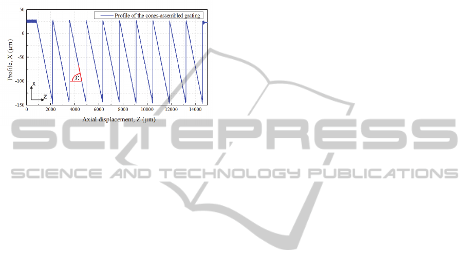
steps is 7.25°.
The average of the measured height is (196.2 ±
2.1 µm) for a theoretical height of 194 µm, the
average of the measured length is (1539.6 ± 4.1µm)
for a theoretical one of 1541.8 µm.
These results are very good for an initial
prototype.
Figure 15: Profile of the measured steps after fabrication.
7 CONCLUSIONS
This paper presents the design of an original fiber-
optic displacement sensor, which will be used to
measure the linear displacement of an axis
performing a helical movement.
First, the geometric model of the sensor principle
was presented in order to obtain the theoretical
geometric parameters. These parameters lead to the
optimal cones-assembled grating, masterpiece of the
long-range displacement measurement principle.
Then, a 10 steps grating prototype of the sensor
was fabricated using a high precision turning
machine with the help of a single crystal-diamond
tool on an aluminium alloy in order to obtain high
precision in the fabricated dimensions, as well as
high reflectivity which ensures good sensor
sensitivity and linearity.
The conical grating prototype was characterised
using Nanofocus
TM
µscan optical profilometer and
the measured parameters are close to the theoretical
ones.
In a near future, this grating will be used together
with two fiber-optic probes to measure on-line the
translation of an axis along several millimeters when
the measuring head of the spindle rotates at 360°
during the translation.
ACKNOWLEDGEMENTS
The Authors would like to thank Cetim (Centre
Technique des Industries Mécaniques) for the
support of this work.
The authors would like to thank B. Bosschaert,
N. Delias and P. E. Karcher, students in Univeristy
of technology of Compiègne, for their help in the
fabrication of the conical grating.
REFERENCES
T. Mukherjee, T.K. Bhattacharyaa, 2012. A Miniature,
High Sensitivity, Surface Micro-machined
Displacement Sensor with High Resolution. The 2012
IEEE/ASME International Conference on Advanced
Intelligent Mechatronics, Kaohsiung, Taiwan.
K.C. Fan, Z. F. Lai, P. Wu, Y. C. Chen, Y. Chen, G. Jager,
2007. A displacement spindle in a micro/nano level,
Measurement Science and Technology
doi :10.1088/0957-0233/18/6/S07.
A. D. Gaikwad, J. P. Gawande, A. K. Joshi, R. H. Chile,
2012. An Intensity-modulated optical fibre
displacement sensor with convex reflector,
International journal of advanced research in
electrical, electronics, and instrumentation
engineering, vol. 1, Issue 1.
Y.G. Lee, Y.Y. Kim, C.G. Kim, 2012. Fiber optic
displacement sensor with a large extendable
measurement range while maintaining equally high
sensitivity, linearity, and accuracy. Review of
Scientific Instruments 83, 045002(2012); doi:
10.1063/1.3698586.
Y. Zhao, P. Li, C. Wang , Z. Pu, 2000. A novel fiber-optic
sensor for small internal curved surface measurement.
Sensors and Actuators A, vol. 86, pp. 211-215.
S.S. Patil, A.D. Shaligram, 2011. Modeling and
experimental studies on retro-reflective fiber optic
micro-displacement sensor with variable geometrical
properties. Sensors and Actuators A, Vol. 172, pp.
428-433.
X. Bingshi, X. Wen , Y. Dong, 2008. A theoretical
analysis on parameters of fiber optic displacement
sensor. Proc. of SPIE, Vol. 7129, pp. 1-6.
F. E. Utou, J. Gryzagoridis, B. Sun, 2006. Parameters
affecting the performance of fiber optic displacement
sensors. Smart Mater. Struct. 15 (2006) S154–S157,
doi: 10.1088/0964-1726/15/1/025.
Y. Alayli, D. Wang, M. Bonis, 1998. Optical fiber
profilometer with submicronic accuracy. Proc. SPIE,
3509.
P.M.B.S. Girão, O.A. Postolache, J.A.B. Faria, J.M.C.D.
Pereira, 2001. An overview and a contribution to the
optical measurement of linear displacement, IEEE
Sens. J. pp. 322–331.
C. Prelle, F. Lamarque, P. Revel, 2006. Reflective optical
sensor for long-range and high-resolution
displacements. Sensors and Actuators A, vol. 127.
A. Khiat, F. Lamarque, C. Prelle, Ph. Pouille, M. Leester-
Schadel and S. Büttgenbach, 2010. Two-dimension
fiber optic sensor for high-resolution and long
PHOTOPTICS2015-InternationalConferenceonPhotonics,OpticsandLaserTechnology
154

range linear measurements. Sensors and Actuators
A, vol. 158, Issue 1.
A. Gautier, H. Khanfir, P. Revel, R.Y. Fillit, 2008. Polish-
miror finish surfaces obtained by high precision
turning, Int. J. Machining and Machinability of
Materials, Vol. 4, Nos. 2/3.
Z.J. Yuan, M. Zhou, S. Dong, 1996. Effect of diamond
tool sharpness on minimum cutting thickness in
ultraprecision machining, J. Mater. Proc. Tech. 62 (4),
pp. 327–330.
Cones-assembledGratingforLong-rangeFiber-opticLinearDisplacementSensor
155
