
Choreography-based Consolidation of Interacting Processes Having
Activity-based Loops
Sebastian Wagner
1
, Oliver Kopp
1,2
and Frank Leymann
1
1
IAAS, University of Stuttgart, Universitaetsstr. 38, Stuttgart, Germany
2
IPVS, University of Stuttgart, Universitaetsstr. 38, Stuttgart, Germany
Keywords:
BPEL, Choreography, Process Consolidation, Loops.
Abstract:
Choreographies describe the interaction between two or more parties. The interaction behavior description
might contain loops. In case two parties want to merge their behavior to gain competitive advantage, the
contained loop constructs also have to be merged. This paper presents a language-independent discussion on
loop-structure pairing in choreographies and possible merging strategies. Thereby, the focus is turned on loops
grouping child activities to be iterated. We show the feasibility of the merging strategies by applying them to
BPEL-based choreographies.
1 INTRODUCTION
Business process consolidation (also called “process
merge”) integrates two or more complementing and
hence often interacting business processes into a single
process. From a business perspective, process consol-
idation is applied by companies to regain control of
outsourced business functions (“business process in-
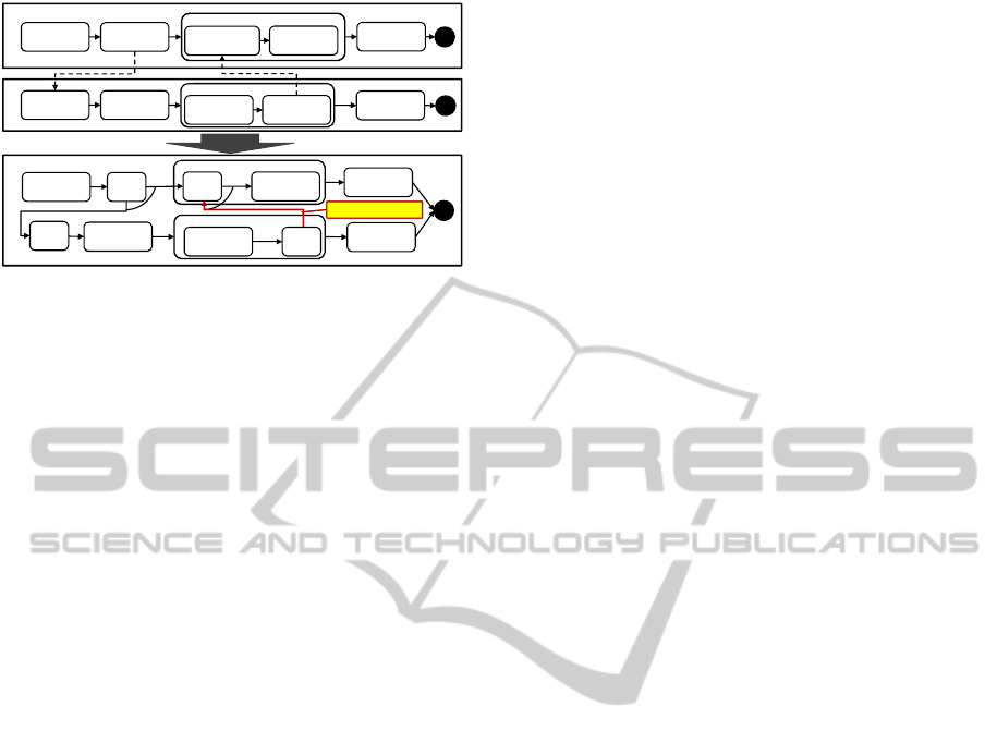
sourcing”). In the scenario in Fig. 1, for instance,
a manufacturer integrates the process of its supplier
in its own process. Beside the business perspective,
there exist also technical drivers for consolidating pro-
cesses. Especially in instance-intensive interaction
scenarios, where hundreds or thousands of process
instances interact with each other, consolidating the
interacting processes may lead to significant perfor-
mance gains (Wagner et al., 2013). They result from
avoiding the costly message transfer steps, i. e., the
message serialization at the sender side, the actual
message transfer and the message deserialization at the
receiver side. Since usually complex XML-based pro-
tocols such as SOAP are used to exchange messages
between processes the message transfer becomes even
more resource intensive (Ng et al., 2004). Another
advantage of consolidating interacting processes is the
decreased number of process instances that have to be
managed by the workflow engines. As typically the
pay-per-use model is applied in Cloud environments,
these performance savings result also in lower costs for
enacting a choreography on a workflow engine being
hosted in the cloud.
To facilitate process consolidation an ap-
proach (Wagner et al., 2012) was developed that
automatically consolidates complementing acyclic
processes, whose interaction behavior is specified by
a choreography, into a single process. The approach
ensures that the consolidated process, called
P
Merged
in the following, generates the same set of traces
of basic activities as the original choreography. To
accomplish that, the approach also adds additional
control links to
P
Merged
to relate activities originating
from the different processes to be consolidated. So
far, the consolidation approach is just capable to
merge acyclic processes. If processes are merged
that interact via activity-based loops, i. e., loops that
contain activities to be iterated in their loop body, the
consolidated process
P
Merged
becomes invalid. This is
due to the fact, that the additional control links created
by the current consolidation approach may cross
loop boundaries. However, workflow languages that
support activity-based loops, such as BPEL (OASIS,
2007) and BPMN (Object Management Group (OMG),
2011), do not allow control links crossing loops
boundaries. For instance, in Fig. 1 the consolidation
created an invalid process because the generated
control link connects the activities “Syn3” and “Syn4”
that are located in different loops.
This work extends the consolidation approach to
support the consolidation of processes that interact
via activity-based loops. For this purpose, we discuss
different interaction patterns involving activity-based
loops communicating with other loops (e. g., graph-
284
Wagner S., Kopp O. and Leymann F..
Choreography-based Consolidation of Interacting Processes Having Activity-based Loops.
DOI: 10.5220/0005443802840296
In Proceedings of the 5th International Conference on Cloud Computing and Services Science (CLOSER-2015), pages 284-296
ISBN: 978-989-758-104-5
Copyright
c
2015 SCITEPRESS (Science and Technology Publications, Lda.)
©SebastianWagner 8
Example Scenario
Manufacturer
Loop– AssembleParts
Supplier
Plan
Manufacturing
SendParts
Order
ReceiveParts
Order
PlanPart
Production
ReceiveDelivery
Notification
Deliver
Product
Loop–PartProduction
ProducePart
SendDelivery
Notification
ml1
Assemble
Part
Manufacturer(P
merged
)
Loop– AssembleParts
Plan
Manufacturing
PlanPart
Production
Deliver
Product
Loop–PartProduction
ProducePart
Assemble
Part
Consolidate
Cross‐Boundary Link
OrderNew
Material
OrderNew
Material
ml2
Syn1
Syn4
Syn2
and
Syn3
and
Figure 1: Consolidation of Interacting Processes.
based loops) by means of a language-independent
workflow meta-model. For each pattern it is discussed
how a consolidation can be performed that keeps the
execution order between basic activities that was de-
fined in the original choreography. We developed
a tool for consolidating interacting BPEL processes.
Therefore, to validate the approach, we will show to
what extend the language-independent patterns can be
mapped to BPEL in order to implement them in the
consolidation tool.
The remainder of the paper is structured as follows.
In Sect. 2 we give a brief overview about the process
consolidation. In Sect. 3 the meta-model of the work-
flow language used in this work is defined. Section 4
describes patterns to resolve the cross-boundary vio-
lations of activity-based loops. In Sect. 5 the patterns
are validated to BPEL and the prototype that imple-
ments the patterns is presented. Section 6 gives an
overview about the related work and in Sect. 7 the
work is concluded.
2 PROCESS CONSOLIDATION
APPROACH
The actual business functions of processes, e. g., hu-
man tasks, data manipulations etc. is implemented by
basic activities, i. e., by activities that do not contain
other activities. The possible set of execution traces
of basic activities during choreography runtime is de-
termined by the control flow constructs (e. g., control
links, loops etc.) and interaction patterns defined in
the choreography. Thus, for being correct,
P
Merged
must be able to generate the same set of traces of ba-
sic activities (without communication activities that
are removed during consolidation) during runtime as
the original choreography, where
P
Merged
was created
from. The same set of traces can be only generated
if
P
Merged
keeps the execution orders between the ba-
sic activities. The execution order between two basic
activities
a
i
and
a
j
defines that
a
i
must be either per-
formed before, after or parallel to
a
j
. To preserve the
execution order, the consolidation operation performs
the following steps:
At first, a single process named
P
Merged
is created.
Then the activities of all interacting processes of the
choreography along with their incoming and outgoing
control links are copied into
P
Merged
. The basic activ-
ities are left in their parent activities (e. g., “Produce
Part” stays in “Part Production”). This ensures that
in
P
Merged
the originally modeled execution order be-
tween the activities originating from the same process
is preserved.
P
Merged
still contains communication activities
used by the processes to interact with each other. These
activities are replaced by synchronization activities
that inherit the control links from the communication
activities replaced by them. For instance, in Fig. 1
“Send Parts Order” and “Receive Parts Order” are re-
placed by “Syn1” and “Syn2” respectively. If the data
flow of the workflow language is modeled by control
flow constructs such as in BPEL, the synchronization
activities can be used to emulate the message transfer.
For instance by copying the former message content
from the data object that was read by the sending ac-
tivity, to the data object where the message content
was copied to by the receiving activity. In BPMN the
synchronization activities just act as sources or tar-
gets for the materialized control links but they do not
perform any operations. In a choreography the exe-
cution order between basic activities originating from
different processes is implicitly defined by the interac-
tion specification, i. e., by the message links (
ml1
and
ml2
in the example). The asynchronous interaction
between “Send Parts Order” and “Receive Parts Or-
der” via message link
ml1
implies that activity “Plan
Manufacturing” is always performed before “Plan Part
Production”. To keep this execution order “control-
flow materialization” is performed, i. e., based on the
interaction type new control links are created. To re-
place an asynchronous interaction the link originates
at the synchronization activity that replaced the send-
ing activity and ends at the synchronization activity
that replaced the receiving activity. These new control
links may cause cross-boundary violations, i. e., they
cross the boundaries of the activity-based loops, as
shown in the example in Fig. 1, which is not permitted
in BPMN or BPEL.
3 PRELIMINARIES
Definition 1
(Process)
.
A process is defined as a di-
rected single entry single exit (SESE) graph
P = (A, E)
.
Choreography-basedConsolidationofInteractingProcessesHavingActivity-basedLoops
285

The set
A
denotes the set of activities and set
E
denotes
the set of control links of the graph. The set of control
links is defined as
E ⊆ A × A ×C
.
C
denotes the set
of link conditions. Conditions are logical expressions
that can be evaluated at runtime of P to true or false.
An activity of a process has a set of incom-
ing control links
E
→
(a) = {(a
i
, a, c)| (a, a
i
, c) ∈
E}
and a set of outgoing control links
E
←
(a) =
{(a, a
i
, c)| (a, a
i
, c) ∈ E}
. The activity where
|E
→
(a)| = 0
is called “entry activity”
a
entry
of
P
and
the activity where
|E
←
(a)| = 0
is called “exit activity”
a
exit
of
P
. The set of directly preceding activities of
an activity
a
is denoted by
•a
and the set of directly
succeeding activities of a are denoted by a•.
The function
PreDom : A → 2
A
returns all activ-
ities that are (pre-)dominated by activity
a
and
a
it-
self (Koehler et al., 2005). An activity
a
dominates
another activity
b
if every path from the entry activity
to
b
goes through activity
a
. All activities that are post-
dominated by activity
a
and
a
itself are returned by the
function
PostDom : A → 2
A
(Koehler et al., 2005). An
activity
a
post-dominates another activity
b
if every
path from
b
to the exit activity goes through activity
a
.
The control flow of a process model follows the
token semantics of BPMN (Object Management Group
(OMG), 2011). The entry activity of
P
propagates a
token to each of its outgoing control links. A link
that receives a token consumes it and evaluates its link
condition. If the link condition evaluates to
true
the
link is activated, i. e., it produces a token and passes it
to its subsequent target activity. An activity is started
(consumes a token) when at least one of its incoming
links is activated and no more upstream tokens may
reach the activity. Informally, this also holds for OR-
joins. Formally, OR-joins have to be Q-enabled to start.
Q-enabledness is defined by V
¨
olzer (V
¨
olzer, 2010).
After the activity is completed, one token is passed
on to each of its outgoing links. The exit activity just
consumes tokens. A process is completed when there
are no other upstream tokens.
Definition 2
(Choreography and Message Links)
.
A
choreography
C = (P , ML)
consists of a set of pro-
cesses
P
and message links
ML ⊆ A × A
. Each mes-
sage link
ML ∈ ML
connects two activities
a
i
and
a
j
from different processes
P
1
, P
2
∈ P
. In a message link
ML = (a
i
, a
j
)
the source activity
a
i
is the sending ac-
tivity and the target activity
a
j
the receiving activity of
a message. An activity must be only source or target of
exactly one message link. A message link is activated,
when
a
i
is started and
a
j
cannot complete until the link
is activated , i. e.,
a
j
“hangs” until the link is activated.
Note, that
a
i
sends a message
m
in a send and forget
manner, i. e.,
a
i
completes, even if
a
j
was not started
yet. We refer to all activities that are source or target
of a message link as communication activities.
In the following different types of loops are de-
fined that are provided by the most workflow lan-
guages (van der Aalst et al., 2003). These loop types
are used, to define the patterns for solving cross-
boundary violations introduced in 4.
Definition 3
(Activity-based Loop)
.
An activity-based
loop
L
is a special type of activity defined as
L = (A
L
⊂
A, E
L
⊂ E, c ∈ C, eval
c
= {pre, post})
. The loop
body is a SESE graph consisting of the activities
A
L
and the control links
E
L
. No control link must cross the
boundary of the loop, i. e.,
∀e ∈ E
L
: π
1
(e), π
2
(e) ∈ A
L
,
where
π
i
projects to the
i
th element of a tuple.
eval
c
is set to
pre
if the loop condition must be evaluated
before the first iteration of the loop body (pre-test loop)
or set to
post
if the loop condition must be evaluated
after the first iteration of the loop body (post-test loop).
The function
Body
:
L → 2
A
× 2
E
returns the graph
in the loop body. The loop condition is returned by
function Cond: L → C.
Activity-based loops can be subdivided in “static
activity-based loops” and “dynamic activity-based
loops”. For static activity-based loops, the maximum
possible number of iterations can be determined dur-
ing design time by using data-flow analysis techniques
(Heinze et al., 2012; Kopp et al., 2008). For dynamic
activity-based loops, this is not possible at design time
but only at runtime. The function
Max
:
L → N ∪ {⊥}
returns the maximum number of iterations of
L
and re-
turns “
⊥
” in the case of dynamic activity-based loops.
The loop body of an activity can be thought of
as a subprocess because it has the same operational
semantics as a process. An activity-based loop that
is started, passes a single token to its entry activity
and the loop completes after all produced tokens were
consumed by its exit activity.
Definition 4
(Graph-based Structured Loop)
.
A graph-
based structured loop
L = (A
L
⊆ A, E
L
⊆ E)
is a sub-
graph of
P
, such that there is an entry node
a ∈ A
L
and an exit node
b ∈ A
L
(which can be the same), such
that every path starting from
a
visits
b
and may visit
the loop entry
a
again and thus forms a cycle. Hence,
all nodes in A
L
are reachable from a.
In this paper, we focus on structured loops and do
not tackle unstructured loops. Finally, we provide a
definition for interacting loops.
Definition 5
(Interacting Loop)
.
Two loops
L1
and
L2
CLOSER2015-5thInternationalConferenceonCloudComputingandServicesScience
286

are called interacting loops, if
∃ml ∈ ML :
(π
1
(ml) ∈ Π
1
(Body(L1))
∧π
2
(ml) ∈ Π
1
(Body(L2)))
∨(π
2
(ml) ∈ Π
1
(Body(L1))
∧π
1
(ml) ∈ Π
1
(Body(L2)))
Informally, this means that
L1
contains a communica-
tion activity
a
i
and that is related to a communication
activity
a
j
in
L2
via a message link
ml
. Note, that
Π
i
returns the set of
i
th elements from the given set of
tuples, here the activities of the body of L1 and L2.
4 SOLVING CROSS-BOUNDARY
VIOLATIONS IN
ACTIVITY-BASED LOOPS
This section describes different patterns to solve cross-
boundary violations created in
P
Merged
by the control-
flow materialization while keeping the execution order
between basic activities. The patterns focus on scenar-
ios with two interacting loops
L1
and
L2
, however, they
can be also applied to more interacting loops, as dis-
cussed at the end of this section. One of the loops must
be an activity-based loop as cross-boundary violations
do only occur if activity-based loops are involved.
In the following, we refer to the set of links that are
crossing boundaries of a loop as
E
CB
⊂ E
. The source
and target activities of a link
e
CB
∈ E
CB
are referred
to as synchronization activities. For interacting graph-
based loops
L1
and
L2 P
Merged
does not have to be
adapted, as graph-based loops do not have a loop body.
Hence, cross-boundary violations cannot occur. The
pattern to be applied depends on the type of
L1
and
L2
receptively and also on the types of loops supported
by the workflow language.
The context of a pattern defines, for what types
of interacting loops it can be applied. The solution
describes how the cross-boundary violation can be
resolved. Variations discusses different variants of
the pattern. The discussion describes how the pattern
preserves the control flow order between the atomic
activities that was originally defined in
C
. The pat-
terns can be only applied to choreographies that are
deadlock free.
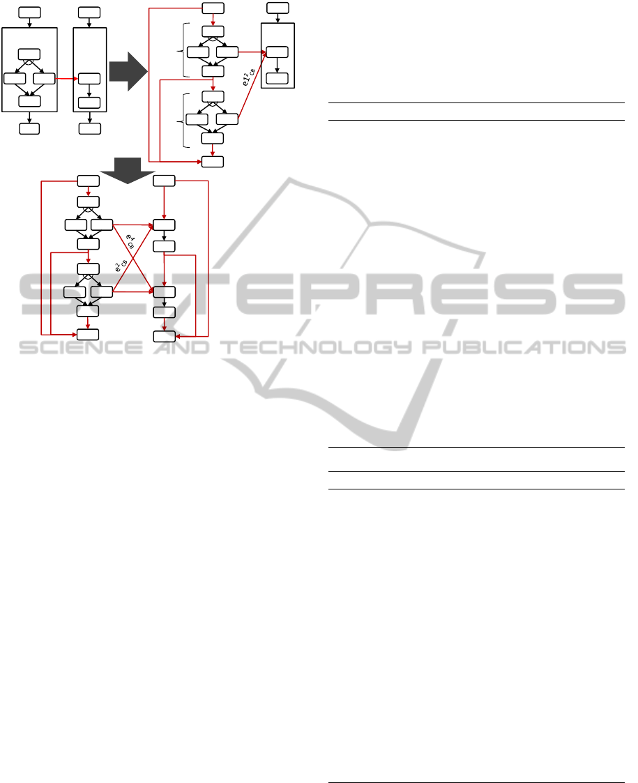
Pattern 1: Activity-based Loop Unrolling
Context.
A static activity-based loop
L1
is related to
another static activity-based loop
L2
via one or more
cross-boundary links as shown in Fig. 2.
L1
and
L2
are not forced to have the same number of iterations.
The workflow language does not support graph-based
structured loops.
Solution.
As the number of iterations of
L1
and
L2
is known at design time loop unrolling (also called
loop unwinding) can be performed on the two loops
to resolve the cross-boundary violations. Algorithm 1
implements loop unrolling for an activity-based loop
L
.
In line 3 the first iteration of
L
is unrolled into
P
Merged
.
All other iterations of L (if any) are unrolled in line 7.
To perform the actual duplication of the loop body
graph the loop unrolling algorithm calls the function
Duplicate
that is shown in Algorithm 2. The func-
tion creates one copy
a
0
of each activity of the given
graph G (line 5). The incoming and outgoing links of
each original activity
a
are also duplicated. These link
copies become the incoming and outgoing links of the
corresponding copy of
a
, i. e.,
a
0
(lines 10 to 15). This
also includes the cross-boundary links. In lines 4 and 8
Algorithm 1 adds the created activity and link copies
to the process graph. As the duplication is performed
n
times, where
n
denotes the max. number of iterations
of
L
,
n
subgraphs
G
1
, . . . , G
1
are created in
P
Merged
.
Subgraph
G
1
L1
represents the first iteration of
L1
,
G
2
L1
the second iteration, etc. For instance, the example
loop
L1
in Fig. 2 is unrolled into two subgraphs
G
1
L1
and
G
2
L1
. Hence, the function
Duplicate
is called twice
by the loop unrolling algorithm. The first call creates
the activity copies
a2
1
-
a5
1
and second call
a2
2
-
a5
2
along with the corresponding link copies.
To preserve the control flow order between the
unrolled iterations of
L
,
G
1
, . . . , G
n
have to be linked
sequentially with each other by a new set of
n − 1
control links (lines 11 to 14 in Algorithm 1) . There-
fore, each exit activity of the subgraphs
G
1
, . . . , G
n−1
is connected to an entry activity of
G
2
, . . . G
n
by a new
control link
e
next
. To emulate the behavior, that another
iteration of
L
is only performed if the loop condition
of
L
evaluates to
true
, the loop condition of
L
is also
added to each link
e
next
. To skip all other iterations if
the loop condition evaluates to
false
after the execution
of an iteration
G
i
, each exit activity of
G
1
, . . . , G
n−1
is
linked to all direct successor activities of
L
via a set
of links
e
skip
(lines 11 - 14). This means, that each
of these links replaces a link from the set of outgo-
ing links of
L
(
E
←
(L)
). Note, that each of the links
from
E
←
(L)
may have also a link conditions assigned.
Hence, each link
e
skip
must be only activated if the loop
condition evaluates to
false
and if the link condition
of the link from
E
←
(L)
it replaces, evaluates to
false
.
The last iteration, i. e.,
G
n
is related to the successor
activities of
L
in the same way by calling Algorithm 4.
To ensure that the direct predecessor activities of
Choreography-basedConsolidationofInteractingProcessesHavingActivity-basedLoops
287
©SebastianWagner 10
Static LoopIEEE
L1
Pre(#2)
a2
a3
a5
a1
a6
e
CB
a2
1
a3
1
a5
1
a1
a6
a2
2
a3
2
a5
2
G
1
L1
G
2
L1
e1
nxt
a4
1
a4
2
a4
b3
b2
e1
skip
e1
exit
e1
entry
e
1
CB
e1
pre
L2
Pre(#2)
b1
b2
b1
L2
Pre(#2)
b1
Unroll
L2
b4
xor
xor
xor
a2
1
a3
1
a5
1
a1
a6
a2
2
a3
2
a5
2
e1
nxt
a4
1
a4
2
e1
skip
e1
exit
e1
entry
e
1
CB
e1
pre
b3
1
b2
1
b1
b3
2
b2
2
e
3
CB
e2
entry
e2
nxt
b4
e2
exit
e2
pre
e2
skip
xor
xor
Unroll
L1
Figure 2: Unrolling of Activity-based Loops.
L
become the predecessors of the unrolled iterations
of
L G
1
, . . . , G
n
Algorithm 3 is called. The algorithm
links the entry activity of
G
1
to the direct predecessor
activities of
L
. For each former incoming link of
L
(i. e.,
E
→
(L)
) a new entry link
e
entry
is created (lines
4 and line 11 in Algorithm 3). If
L
is a post-test loop,
the link conditions of the entry links inherit the link
conditions of the incoming links
E
→
(L)
(line 11 in
Algorithm 3). This ensures the originally modeled
behavior, that the first iteration is always started, if at
least one of the incoming links of L is activated.
If
L
is a pre-test loop the first iteration of the loop
body must be only started if at least one of the incom-
ing links of
L
is activated and if the loop condition
evaluates to
true
. To emulate this behavior, the link
conditions of the entry links are concatenated with the
loop condition of
L
. To skip the execution of the un-
rolled loop if the pre-test loop condition evaluates to
false
another set of links
E
pre
⊂ E
is created between
all direct predecessor and successor activities of L
To guarantee that an activity, target of a copy of a
cross-boundary link
e
i
CB
, is performed at most once a
Boolean flag is added to
P
Merged
and accessed by the
link condition of all copies
e
i
CB
of a cross-boundary
link
e
CB
(due to space reasons not shown in the pre-
sented algorithms). This flag carries the name of the
original cross-boundary link and it is set from
true
to
false
when a copy
e
i
CB
was activated. Thus, any
another copy
e
j
CB
of
e
CB
(
i 6= j
) cannot be activated
anymore, which prevents its target activity from be-
ing executed again. For instance, if in Fig. 2 the path
ha2
1
, a3
1
, a5
1
i
is taken,
e
1
CB
is activated and
b2
1
is ex-
ecuted which causes the flag to be set to
false
. If the
execution continues on the path
ha2
2
, a3
2
, a5
2
i
the link
condition of
e
2
CB
deactivates this link and prevents
b2
1
from being started again.
Algorithm 1: Loop Unrolling.
1: procedure UNROLL-LOOP(L)
2: i ← 1
3: G
i
← DUPLICATE(Body(L))
4: P
Merged
← P
Merged
∪ G
i
5: ADD-TO-LOOP-PREDECESSORS(G
i
,L)
6: while i < Max(L) do
7: G
i+1
← DUPLICATE(G
i
)
8: P
Merged
← P
Merged
∪ G
i+1
9: e
next
= (Exit(G
i
), Entry(G
i+1
), Cond(L))
10: ADD-LINK(P
Merged
, e
next
) Add link to
P
Merged
11: for all e
succ
∈ E
←
(L) do
12: e
skip
= (Exit(G
i
), π
2
(e
succ
),
(π
3
(e
succ
) ∧ ¬Cond(L)))
13: ADD-LINK(P
Merged
, e
skip
)
14: end for
15: i ← i + 1
16: end while
17: RELATE-TO-LOOP-SUCCESSORS(G
i−1
,L)
18: end procedure
Algorithm 2: Graph Duplication.
1: function DUPLICATE(G)
2: A = Π
1
(G) Original activities
3: A
0
= {}; E
0
= {} Activity and link copies
4: for all a ∈ A do
5: a
0
= DUPLICATE-ACTIVITY(a)
6: A
0
← A
0
∪ a
0
7: end for
8: for all a
0
∈ A
0
do
9: a = GET-ORIGIN(a
0
) Get original activity
10: for all e
in
∈ E
→
(a) do
11: E
0
← E
0
∪ ADD-LINK(π
1
(e
in
), a
0
, π
3
(e
in
))
12: end for
13: for all e
out
∈ E
←
(a) do
14: E
0
← E
0
∪ ADD-LINK(a
0
, π
2
(e
out
), π
3
(e
out
))
15: end for
16: end for
17: return G
0
= (A
0
, E
0
)
18: end function
Variations.
For resolving cross-boundary violations
between two interacting static activity-based loops
L1
and
L2
, both loops have to be unrolled. The order
in which
L1
and
L2
are unrolled by Algorithm 1 is
CLOSER2015-5thInternationalConferenceonCloudComputingandServicesScience
288

not relevant because the loop unrolling technique nei-
ther considers nor changes the structure of the other
loop. Also if
L1
and
L2
have a different number of
maximal iterations the unrolling can be performed as
the cross-boundary links are duplicated for each itera-
tion. Which, in turn, keeps the control flow relations
between each unrolled iteration of L1 and L2.
A dynamic activity-based loop
L1
without
synchronization activities on alternative paths in
its loop body can be unrolled, if it interacts with
a static activity-based loop
L2
that does not have
synchronization activities on alternative paths either.
The number of unrolled iterations of
L1
is implied
by the maximum number of iterations of
L2
. Each
execution of a synchronization activity
a
from
L1
connected to a synchronization activity
b
from
L2
via
a link
e
cb
(a, b, true)
results in an execution of
b
and
vice versa. Hence, the maximum number of iterations
of
L2
implies the maximum number of iterations of
L1
.
Algorithm 3: Add Loop Predecessors.
1: procedure
ADD-TO-LOOP-PREDECESSORS(
G
,
L)
2: for all e
pred
∈ E
→
(L) do
3: if eval
C
(L) = pre then
4: e
entry
= (π
1
(e
pred
), Entry(G),
(π
3
(e
pred
) ∧ Cond(L) = true))
5: ADD-LINK(P
Merged
, e
entry
)
6: for all e
succ
∈ E
←
(L) do
7: e
pre
= (π
1
(e
pred
), π
2
(e
succ
),
(π
3
(e
pred
) ∧ π
3
(e
succ
) ∧ ¬Cond(L)))
8: ADD-LINK(P
Merged
, e
pre
)
9: end for
10: else
11: e
entry
= (π
1
(e
pred
), Entry(G), π
3
(e
pred
))
12: ADD-LINK(P
Merged
, e
entry
)
13: end if
14: end for
15: end procedure
Algorithm 4: Add Loop Successors.
1: procedure ADD-TO-LOOP-SUCCESSORS(G, L)
2: for all e
succ
∈ E
←
(L) do
3: e
exit
= (Exit(G), π
2
(e
succ
),
4: (π
3
(e
succ
) ∧ ¬Cond(L))
5: ADD-LINK(P
Merged
, e
exit
)
6: end for
7: end procedure
Discussion.
The consecutive execution of the iter-
ations of an unrolled loop
L
is emulated by dupli-
cating the loop body of
L n
times to the subgraphs
G
1
L
, . . . , G
n−1
L
and by linking these subgraphs sequen-
tially. The control relations within the activities of
the duplicated loop bodies are preserved as no new
activities or control links are introduced in
G
i
L
. The
behavior, that no further iteration of
L
is performed
when its loop condition evaluates to
false
, is emulated
by the set of additional control links
E
skip
connecting
the exit activity of each unrolled subgraph
G
i
L
with the
successor activities of L.
The loop unrolling technique keeps also the con-
trol flow relations between the activities of
L1
and
L2
implied by
C
as the links
E
CB
are also duplicated. As-
sume, for instance, that
L1
in Fig. 2 can be iterated
up to six times and
L2
only up to two times. Hence,
L1
has to be unrolled six times and
L2
two times. If
C
is deadlock free, the path
ha2, a3, a5i
in
L1
must
be taken exactly in two iterations to execute
b2
and
b3
. However, it can not be determined at design time,
which iterations take this path. The duplication of
the cross-boundary link
e
CB
ensures, that taking this
path is possible in each unrolled iteration
G
i
L1
. At the
same time, multiple executions of the same activity
are avoided by using the flag that tracks, if a copy of
a cross-boundary link was already performed. This
also implies that a target activity of one or many cross-
boundary links does not run into deadlocks. If it ran
into a deadlock, none of the source activities of their
incoming cross-boundary link is performed. As each
cross-boundary link represents a former message ex-
change in
C
, this, in turn, would mean that the target
activity would wait forever for an incoming message.
Hence,
C
would not be deadlock free which contra-
dicts to our prerequisite.
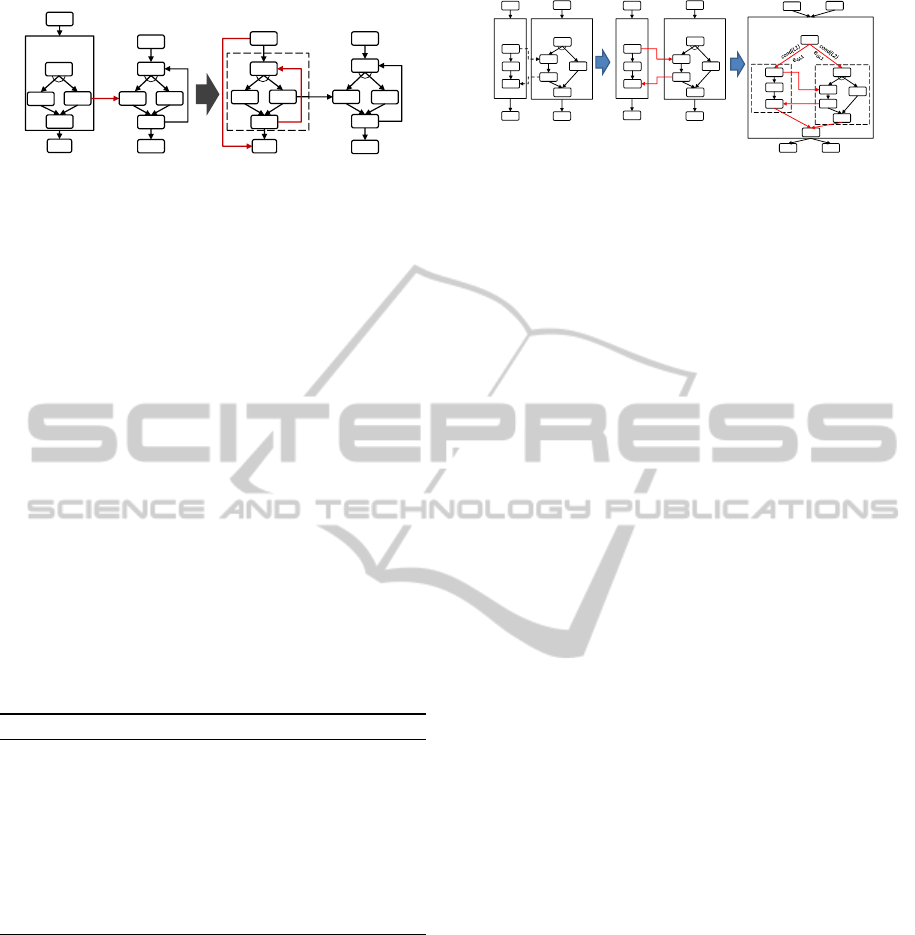
Pattern 2: Transforming Activity-based
Loops to Graph-based Structured Loops
Context.
A dynamic activity-based loop
L
is related
to another static or dynamic graph-based structured
loop via a set of cross-boundary links as shown in
Fig. 3. The workflow language supports graph-based
structured loops.
Solution.
To resolve the cross-boundary violations,
L
can be transformed to a graph-based structured loop
L
G
by copying the loop body
G
L
of
L
to
P
Merged
and
by creating a control flow cycle between the exit and
entry activity of
G
L
. Algorithm 5 describes the trans-
formation in detail.
The actual duplication of the loop body of
L
is done
in line 2. To realize the repetitive execution of
G
L
a
control flow cycle between the exit activity
a
exit
and
the entry activity
a
entry
is created in line 5 by adding
the new control link
e
loop
. For instance in Fig. 3, the
Choreography-basedConsolidationofInteractingProcessesHavingActivity-basedLoops
289
©SebastianWagner 13
Activity‐based – Graph‐based
L1
Pre(#?)
a2
a3
a5
a1
a6
e1
CB
a4
b5
b3
b2
b4
b1
b6
a2
a3
a5
a1
a6
e1
CB
a4
b5
b3
b2
b4
b1
b6
G
l1
e
loop
e
skip
L1
Pre(#?)
a2
a3
a5
a1
a6
ml1
a4
b5
b3
b2
b4
b1
b6
xor
xor
xor
xor
xor
xor
L1
Pre(#?)
a2
a3
a5
a1
a6
e1
CB
a4
b5
b3
b2
b4
b1
b6
a2
a3
a5
a1
a6
e1
CB
a4
b5
b3
b2
b4
b1
b6
G
l1
e
loop
e
skip
xor
xor
xor
xor
Figure 3: Activity-based Loops to Graph-based Structured
Loops.
link
e
loop
connects the exit activity
a5
with the entry
activity
a2
. To incorporate
G
L
into the process graph
of P
Merged
Algorithm 5 calls Algorithm 3 and 4.
As described in pattern 1, Algorithm 3 is used to
ensure that the set of direct predecessor activities of
L
become predecessors of the entry activity of
G
L
by
creating a set of entry links (denoted as
e
entry
). This
means, that if
L
is a post-test loop, the entry links
inherit the link conditions of the original entry links of
L
. If
L
has a pre-test condition, it has to be guaranteed,
that the first iteration of
G
L
is only performed if the
loop condition evaluates to
true
, otherwise
G
L
must be
skipped.
Algorithm 4 is called, to relate the direct successor
activities of
L
with the exit activities
G
L
by creating for
each outgoing link of
L
(
e ∈ E
←
(L)
) a corresponding
exit link
e
exit
. To start the successor activities if and
only if all iterations of
G
L
completed, the link condi-
tion of each exit link is concatenated with a negation
of the loop condition of L.
Algorithm 5: Loop Transformation.
1: procedure LOOP-TRANSFORM(L)
2: G
L
← DUPLICATE(Body(L))
3: P
Merged
← P
Merged
∪ G
L
4: ADD-TO-LOOP-PREDECESSORS(G
L
,L)
5: e
loop
= (Exit(G
L
), Entry(G
L
), Cond(L))
6: ADD-LINK(P
Merged
, e
loop
)
7: ADD-TO-LOOP-SUCCESSORS(G
L
,L)
8: end procedure
Variations.
Transforming a static structured loop
L
to an unstructured loop instead of unrolling it (as
described in Sect. 4), may be useful if
L
has a high
maximum of iterations. This avoids
P
Merged
to be
“polluted” with unrolled iterations of L.
Discussion.
Transforming an activity-based loop
L
to
a graph-based structured loop
L
G
removes the loop
boundaries of
L
while preserving all control flow con-
straints implied by
C
. The control link
e
loop
enables
iterations of the loop body
G
L
to be consecutively exe-
cuted, as long as the loop condition evaluates to
true
.
As the loop condition is not changed,
L
G
is iterated
©SebastianWagner 15
G
L2
G
L1
Dynamicand DynamicLoop
L
L1L2
Post(#?)‐ (cond(L1) OR cond(L2))
a
entry
a
end
a1
b1
a5 b7
L1
Pre(#?)
a2
L2
Pre(#?)
b2
a3
a4
b3
b6
b5
a1
b1
a5
b7
b4
L1
Pre(#?)
a2
L2
Pre(#?)
b2
a3
a4
b3
b6
b5
a1
b1
a5
b7
b4
a2 b2
a3
a4
b3
b6
b5
b4
e1
CB
e2
CB
e1
CB
e2
CB
xor
xor
xor
Figure 4: Merging Two Dynamic Activity-based Loops.
as often as
L
(under the same data assignment). If the
loop condition evaluates to
false
, link
e
loop
is deacti-
vated and the exit links
E
←
(exit)
are activated. This
ensures the original behavior, that the successors of
L
are started after all iterations of
L
completed. The orig-
inal control relations between
L1
and other loops are
also preserved since the cross-boundary links between
are not changed either.
Pattern 3: Merging Two Dynamic
Activity-based Loops
Context.
A dynamic activity-based loop
L1
is related
to another dynamic activity-based loop
L2
via a set
of cross-boundary links as shown in Fig. 4. The
workflow language does not support graph-based
structured loops.
Solution.
Loop unrolling cannot be performed as the
number of iterations of
L1
and
L2
is unknown at design
time. To resolve the violations, the source and target
activities of these links are moved into the same loop,
referred to as
L
L1L2
. Thus, the activity graphs
G
L1
and
G
L2
have to be merged into a new single loop
L
L1L2
as
shown in Algorithm 6.
The algorithm creates the new loop
L
L1L2
in line
4. The loop body
G
L1L2
of this loop, which consists
of of the loop bodies of
L1
and
L2
, is created in line 5.
Additionally, an entry activity
a
entry
and an exit activ-
ity
a
exit
is added to the loop body. These activities
precede and succeed the entry and exit activities of
G
L1
and
G
L2
. They are added to keep the SESE prop-
erty and to ensure that
G
L1
is only performed, if the
loop condition of
L1
becomes
true
and that
G
L2
is only
performed, if the loop condition of
L2
becomes
true
.
For this purpose, the transition condition of the entry
link pointing from
a
entry
to
G
L1
gets the loop condition
of
L1
assigned and the the entry link pointing from
a
entry
to
G
L2
gets the join condition of
L2
assigned.
Moreover, the link condition of the entry link is con-
joined by an additional flag
firstIt 7→ {true, false}
if the
loop body
G
L1
or
G
L2
originates from a post-test loop
(lines 10 and 13). If the first iteration of
L
L1L2
is exe-
cuted the flag is set to
true
, otherwise it is set to
false
.
For instance, in Fig. 4 the entry link for
e
GL2
) would be
CLOSER2015-5thInternationalConferenceonCloudComputingandServicesScience
290

defined as
(a
entry
, b2, Cond(L2) ∨
0
firstIt = true
0
)
. The
value of the flag is hold in the variable
firstIt
that is de-
clared in
P
Merged
(line 8). After the first iteration
firstIt
must be set to false (not depicted in Algorithm 6).
L
L1L2
is always a post-test loop (see below), no
matter if
L1
,
L2
or both are pre-test loops. The loop
condition of
L
L1L2
is set to the logical disjunction of
the loop conditions of
L1
and
L2
(line 16). This en-
sures that
G
L1L2
is also executed if the condition of
L1
evaluates to
false
while the condition of
L2
evaluates
to
true
(or vice versa). In Fig. 4, for instance, under
a certain data assignment
L1
may iterate two times
and
L2
five times. To emulate this behavior,
L
L1L2
must be iterated five times which ensured by its loop
condition. Since the link condition of the entry link
(a
start
, a2, Cond(L1))
is set to the loop condition of
L1
its body
G
L1
is just performed twice.
L
L1L2
is wired
into
P
Merged
by connecting it to the predecessor and
successor activities of L1 and L2 (lines 17 and 18).
Algorithm 6: Merging Activity-based Loops.
1: function MERGE-LOOPS(L1, L2)
2: G
L1
← DUPLICATE(Body(L1))
3: G
L2
← DUPLICATE(Body(L2))
4: L
L1L2
= ADD-LOOP(
/
0,
/
0, eval
C
← post)
5: Body(L
L1L2
) ← G
L1
∪ G
L2
∪ ({a
exit
},
{(Exit(G
L1
), a
exit
, true), (Exit(G
L2
), a
exit
, true)})
6: condEntry
L1
← Cond(L1)
7: condEntry
L2
← Cond(L2)
8: DECLARE(P
Merged
, f irstIt) Adds variable
9: if eval
C
(L1) = post then
10: condEntry
L1
← condEntry
L1
∨
0
$firstIt = true
0
11: end if
12: if eval
C
(L2) = post then
13: condEntry
L2
← condEntry
L2
∨
0
$firstIt = true
0
14: end if
15: Body(L
L1L2
) ← Body(L
L1L2
) ∪ ({a
entry
},
{(a
entry
, Entry(G
L1
), condEntry
L1
),
(a
entry
, Entry(G
L2
), condEntry
L2
)})
16: Cond(L
L1L2
) ← (Cond(L1) ∨ Cond(L2))
17: E
→
(L
L1L2
) ← E
→
(L1) ∪ E
→
(L2)
18: E
←
(L
L1L2
) ← E
←
(L1) ∪ E
←
(L2)
19: return L
L1L2
20: end function
Variations.
If a dynamic activity-based loop, with
synchronization activities on alternative paths in
its loop body, is related to a static activity-based
loop, its number of iterations cannot be determined
from the max. number of iterations of the static
loop (refer to pattern 1). Hence, the dynamic loop
cannot be unrolled and has to be merged with the
static loop in the same way as described in the solution.
Discussion.
Merging
L1
and
L2
into
L
L1L2
keeps the
original control flow order between the activities of
G
L1
and
G
L2
as the control links are not changed. The
loop condition of
L
L1L2
and the link conditions of the
entry links ensure that the same number of iterations
of
G
L1
and
G
L2
are executed as in
C
(under the same
data assignment). However, the activities of
G
L1
and
G
L2
become iteration-dependent on each other, i. e.,
another iteration
i + 1
of the activities in
G
L1
cannot
be performed until all activity iterations
i
in
G
L2
com-
pleted (and vice versa). This becomes especially an
issue, if the execution times of the activities within
G
L1
and
G
L2
are very different from each other. It also
postpones the execution of the successor activities of
L
L1L2
. For instance, in 4
a5
cannot be started until all
iterations of
L
L1L2
completed, i. e., compared to
C
its
execution is postponed until all iterations of
G
L1
com-
pleted. Note, that the postponed execution resulting
from the loop merge may increase the time until the
business outcome is reached, but it does not affect the
overall completion time of
P
Merged
compared to
C
. The
successful completion of all activities of an instance
of P
Merged
takes as long as completing all activities of
C
(assuming the same data are used for an instance of
P
Merged
and C ).
Combining the Patterns
In the following two algorithms are proposed that
make use of the patterns to solve cross-boundary vi-
olations in
P
Merged
. If graph-based structured loops
are supported by the workflow language, the set of all
dynamic or static activity-based loops being source or
target of a cross-boundary link (denoted as
L
CB
) are
transformed into graph-based structured loops by Al-
gorithm 7. The transformation preserves all sets of
basic activity traces implied by the original loop and
it just adds the two new links
e
skip
and
e
loop
to
P
Merged
.
The runtime of the algorithm is
O(n)
, where
n = |L
CB
|
.
Algorithm 7: Transformation to Graph-based Loops.
1: procedure SOLVE-CB-VIOLATIONS(L
CB
)
2: for all L
CB
∈ L
CB
do
3: LOOP-TRANSFORM(L
CB
)
4: REMOVE-ACT(P
Merged
, L
CB
)
5: end for
6: end procedure
If graph-based loops are not supported Algorithm 8
must be applied. It tries to unroll as many loops within
L
CB
as possible (pattern 1). All loops that cannot be
unrolled, i. e., all interacting dynamic activity-based
loops and all static activity-based loops that interact
with dynamic activity-based loops, are merged into
activity-based loops (pattern 3). Applying pattern 1
decreases the readability of
P
Merged
as it may signif-
Choreography-basedConsolidationofInteractingProcessesHavingActivity-basedLoops
291

icantly increase the number of activities and control
links in
P
Merged
. Especially if a large number of iter-
ations is unrolled. However, as pattern 3 causes the
iteration-dependency issue, pattern 1 is always pre-
ferred to pattern 3.
Algorithm 8: Merging and Unrolling.
1: procedure SOLVE-CB-VIOLATIONS(E
CB
, L
CB
)
2: for all L1
CB
∈ L
CB
| MAX(L1
CB
) = ⊥ do
3: A
L
= Π
1
(BODY(L1
CB
))
4: for all e
CB
∈ E
CB
5: | (π
1
(e
CB
) ∪ π
2
(e
CB
)) ∩ A
L
6=
/
0 do
6: L1
CB
= PARENT(π
1
(e
CB
))
7: L2
CB
= PARENT(π
2
(e
CB
))
8: L
merged
= MERGE-LOOPS(L1
CB
, L2
CB
)
9: ADD-ACT(P
Merged
, L
merged
)
10: L
CB
← (L
CB
∪ L
merged
) − (L1
CB
∪ L2
CB
)
11: A
L1
= Π
1
(BODY(L1
CB
))
12: A
L2
= Π
2
(BODY(L2
CB
))
13: E
L1L2
CB
= {e
L1L2
CB
| ∀e
L1L2
CB
∈ E
CB
:
((A
L1
∪ A
L2
) ∩ π
1
(e
L1L2
CB
)) 6=
/
0
∧((A
L1
∪ A
L2
) ∩ π
2
(e
L1L2
CB
)) 6=
/
0}
14: E
CB
← E
CB
− E
L1L2
CB
15: REMOVE-ACT(P
Merged
, L1
CB
)
16: REMOVE-ACT(P
Merged
, L2
CB
)
17: L1
CB
← L
merged
18: A
L
= Π
1
(BODY(L1
CB
))
19: end for
20: L
CB
← L
CB
− L
merged
21: end for
22: for all e
CB
∈ E
CB
do
23: a
L1
= π
1
(e
CB
); a
L2
= π
2
(e
CB
)
24: L1
CB
= PARENT(a
L1
)
25: L2
CB
= PARENT(a
L2
)
26: UNROLL-LOOP(L1
CB
)
27: UNROLL-LOOP(L2
CB
)
28: L
CB
← L
CB
− (L1
CB
∪ L2
CB
)
29: end for
30: end procedure
Algorithm 7 is trivial and not further discussed.
Algorithm 8 is explained by using the example sce-
nario in Fig. 5. In this scenario
P
Merged
contains four
dynamic and two static activity-based loops. The con-
trol flow materialization created six cross-boundary
links. To resolve the violations the algorithm is called
with the parameters
E
CB
and
L
CB
. Thereby, the set
E
CB
denotes the set of cross-boundary links, here
e1
CB
to
e4
CB
.
L
CB
contains those loops of
P
Merged
that are
source or target of one or more cross-boundary links,
i. e., in the scenario
L1
to
L4
. In a first step, those loops
within
L
CB
that are related to a dynamic activity-based
loop via a cross-boundary link are merged. For this
purpose the algorithm selects a dynamic activity-based
©SebastianWagner 17
ExampleSolveViolationwithMergingandUnrolling
L1
Pre(#?)
e1
CB
e2
CB
L2
Pre(#?)
L3
Post(#3)
L4
Pre(#6)
e3
CB
e4
CB
L5
Pre(#?)
e5
CB
e6
CB
L6
Pre(#2)
Figure 5: Multiple Interacting Activity-based Loops.
loop from
L
CB
(line 4), e. g.,
L1
. All loops contain-
ing activities that are related to activities within the
selected loop via a cross-boundary link (line 4) are pair-
wise merged with the selected loop. For instance,
L1
is first merged with
L2
and the resulting loop
L
merged
is
added to
P
Merged
(line 9) while
L2
and
L1
are removed
from
P
Merged
(lines 15 and 16). As the cross-boundary
violations between the merged loops are resolved, all
cross-boundary links between them are removed from
the set
E
CB
in line 13 (but not from
P
Merged
). Hence,
after
L1
and
L2
were merged
e1
CB
and
e2
CB
are re-
moved. Then all loops that are related to the merged
loop via cross-boundary links are merged with
L
merged
,
i. e., in our example the static loop
L3
is merged with
L
merged
. The new merged loop consisting of the loop
bodies of
L1
,
L2
and
L3
is then, in turn, merged with
L4
. As this new loop has no cross-boundary links to
other loops, it is removed from the set
L
CB
(line 20)
and another dynamic loop whose activities are source
or target of cross-boundary links is selected (if any).
In our example this would be
L5
or
L6
, which are also
merged with each other.
After the dynamic loops were merged with other
dynamic or static loops,
P
Merged
contains only cross-
boundary links between static loops. These loops are
unrolled and added to
P
Merged
. Our example does only
contain static loops that are transitively connected to
dynamic loops. Hence, no loop unrolling is performed
here. The runtime of the algorithm is also
O(n)
(where
n = |L
CB
|
), even though it has two nested for-loops.
However, the for-loop in line reduces the iterations of
its parent for-loop (line ) by removing cross-boundary
loops from the set L
CB
.
5 VALIDATION:
CONSOLIDATION OF BPEL
PROCESSES WITH
INTERACTING LOOPS
To validate the process consolidation approach we
developed a tool (Dadashov, 2013) that merges inter-
acting BPEL processes being part of a BPEL4Chor
choreography (Decker et al., 2009) into a single pro-
cess. So far, the prototype was not capable to merge
BPEL processes with interacting loops. To support
these interaction scenarios, we applied the patterns
of Sect. 4 to BPEL and extended the prototype ac-
CLOSER2015-5thInternationalConferenceonCloudComputingandServicesScience
292

cordingly. The prototype gets a ZIP file as input, that
contains an XML representation of BPEL4Chor chore-
ography along with the processes to be merged. To per-
form the consolidation, the prototype creates
P
Merged
and copies all activities of the processes within the
BPEL4Chor choreography into
P
Merged
. Based on the
message links and the communication activities in the
BPEL4Chor choreography the prototype performs the
control flow materialization.
5.1 Control Flow Semantic of BPEL
Besides control links BPEL uses join conditions to
determine if an activity can be started. A join condi-
tion specifies which links have to be activated to start
this activity. This requires the status of all links to be
known before the join condition is evaluated. More-
over, BPEL is using a dead path elimination control
flow semantics (DPE) that determines all activities in
the control flow that cannot be executed anymore. Due
to the DPE semantics and the fact that all links of an
activity have to be evaluated before it can be started,
BPEL does not support graph-based loops.
To enable repetitive execution of activities, BPEL
offers three types of activity-based loops, the pre-
test loops
while
and
forEach
and the post-test loop
repeatUntil
.
while
and
repeatUntil
loops are de-
fined in the same way as the activity-based loops de-
fined in Sect. 3, i. e., they consist of a Boolean loop
condition and an activity graph in their loop body. For
simplicity reasons, we assume that the loop body is a
SESE graph, even though this not stipulated by BPEL
. The
forEach
activity has no Boolean expression as
loop condition but a
From
and
To
attribute, represent-
ing the start and end value of the iteration counter. The
attribute
Counter
provides the name of the counter
variable that is increased by one in each iteration. The
attribute values can be determined at runtime but they
must be constant during the execution of the
forEach
.
All iterations have to be executed in order to com-
plete the
forEach
loop. The
completionCondition
attribute for modeling at-least-n-out-of-m semantics is
not considered here.
5.2 Applying the Patterns to BPEL
This section describes how patterns 1 and 3 from
Sect. 4 are applied to BPEL. Pattern 2 is not further
considered here as BPEL does not support graph-
based structured loops.
Activity-based Loop Unrolling.
To determine the
maximum iterations of a BPEL loop the data flow anal-
ysis techniques introduced by Heinze et al. (Heinze
et al., 2012) are used. However, the pattern cannot
be applied to arbitrary static activity-based loops. Be-
cause BPEL’s link semantic requires that all incoming
links of an activity are evaluated before it is started.
However, if a loop is unrolled also the cross-boundary
links
E
CB
are duplicated. This results in
n
multiple
copies of
e
CB
targeting the same activity, where each
copy has its source in one of the unrolled iterations
G
1
L
, . . . , G
n
L
of the loop
L
. Hence, the source activity of
each copy of
e
CB
must be performed before the target
activity of
e
CB
can be executed. In Fig. 2, for instance,
activity
b2
1
is not started until
a3
1
and
a3
2
completed.
In the example, this just leads to a postponed execution
of
b2
1
compared to
C
where the first iteration of
b2
can complete after the first iteration of
a3
is performed
(if we assume that messages are instantly delivered).
If
L2
would contain an activity that is source of a link
e2
CB
targeting an activity within the unrolled loop
L1
,
this would even lead to a deadlock.
This issue is circumvented by ensuring that the
activities
A
L1
and
A
L2
in the unrolled loops
G
L1
and
G
L2
have at most one incoming cross-boundary link
e
i
CB
:
∀a ∈ A
L1
∪ A
L2
: |(E
→
(a) ∪ E
←
(a)) ∩ E
CB
| ≤ 1
This, in turn, requires the source and target activities
of
E
CB
to be performed during each iteration. Thus,
there must be no potential alternative paths in
L1
or
L2
preventing synchronization activities from being
executed during an iteration of L1 or L2:
∀a
L1
∈A
L1
| (E
→
(a
L1
) ∪ E
←
(a
L1
)) ∈ E
CB
:
PreDom(a
L1
) ∪ PostDom(a
L1
) = A
L1
∀a
L2
∈A
L2
| (E
→
(a
L2
) ∪ E
←
(a
L2
)) ∈ E
CB
:
PreDom(a
L2
) ∪ PostDom(a
L2
) = A
L2
If the aforementioned prerequisite is fulfilled, a copy
of a cross-boundary link has to be connected to a
source and target activity part of the subgraph
G
i
L1
and
G
i
L2
in the same iteration, i. e., the source and tar-
get activities must dominate the same number of sync.
activities A
syn
:
∀e
i
CB
∈ E
CB
:
|PreDom(π
1
(e
i
CB
)) ∩ A
CB
|
= |PreDom(π
2
(e
i
CB
)) ∩ A
CB
|
A
CB
=
[
e∈E
CB
π
1
(e) ∪ π
2
(e)
The set
A
CB
denotes the set of activities of
L1
and
L2
having an incoming or outgoing cross-boundary link.
Figure 6 shows a
while
loop
L1
(
Max(L1) = 2
) in-
teracting with a
repeatUntil
loop
L2
(
Max(L2) = 2
)
that meet the aforementioned properties (in the figure
Choreography-basedConsolidationofInteractingProcessesHavingActivity-basedLoops
293
©SebastianWagner 12
Static Unrolling of BPELLoops(without Chor)
L1– While
Pre(#2)
a2– Assign
L2– RepeatUntil
Post(#2)
b2–Empty
a3– Opaque
a4–Empty
b3– Opaque
b4– Assign
a2
1
– Assign
b2
1
–Empty
a3
1
– Opaque
a4
1
–Empty
b3
1
– Opaque
b4
1
– Assign
a2
2
– Assign b2
2
–Empty
a3
2
– Opaque
a4
2
–Empty
b3
2
– Opaque
b4
2
– Assign
e1
1
CB
e1
CB
e2
CB
e2
1
CB
e1
1
CB
e2
1
CB
e1
skip
e2
nxt
a1– Assign
b1– Assign
a1– Assign b1– Assign
a5– Assign
b5– Assign
a5– Assign
b5– Assign
e1
nxt
e1
pre
e2
skip
Figure 6: Unrolling Two Static BPEL Loops.
the
opaque
activities encapsulate some business
logic). As there is no alternative flow in
L1
and
L2
they have to exchange messages during each
iteration. This also implies that they always perform
the same number of iterations. Hence, the copies
of the cross-boundary links (
e1
1
CB
,
e1
2
CB
and
e2
1
CB
,
e2
1
CB
) between the unrolled loop
G
L1
and
G
L2
must
only connect activities from the same iterations. As
shown in Figure 6,
while
or
repeatUntil
loops are
unrolled in the same way as described in the pattern,
i. e., the loop bodies are unrolled and added to the
container activity of
L1
and
L2
(not depicted here).
The set of links
E
nxt
,
E
skip
,
E
entry
,
E
exit
connects the
unrolled iterations with each other and with the direct
predecessor and successor activities of
L
. The link
e
pre
has to be only added for the pre-test loops
while
or
forEach
. In contrast to the pattern, for an unrolled
forEach
loop no loop condition is assigned to
e
nxt
as
a sequential
forEach
cannot be interrupted, i. e., the
maximum number of iterations is always performed.
Thus, the set of links E
skip
is not required either.
Merging Two Dynamic Activity-based Loops.
If
the interacting loops
L1
and
L2
are
while
loops the
pattern can be directly applied. Then
L
L1L2
is also a
while
loop whose loop condition is the disjunction of
the loop conditions of
L1
and
L2
. The loop body of
L
L1L2
is created as described in the pattern. If one of
the entry links of
G
L1
or
G
L2
evaluates to
f alse
, DPE
ensures that the activities within
G
L1
or
G
L2
are not
performed.
If one of the loops
L1
or
L2
is a
repeatUntil
loop
the variation of the pattern for post-test loops has to be
applied, i. e.,
L
L1L2
must be also a
repeatUntil
loop.
If a
forEach
loop interacts with a
while
loop the
merged loop
L
L1L2
must be a
while
loop because the
loop condition of a
forEach
loop cannot specify com-
plex logical expressions such as disjunctions. To spec-
ify the loop condition of
L
L1L2
, the interval defined
by the
From
and
To
attributes of the
forEach
is trans-
formed to a logical expression on the counter variable.
In a
forEach
the counter variable is automatically in-
creased with each iteration. This has to emulated in
©SebastianWagner 17
ForEach‐While
L1– While
($a < 3)
a1– Opaque
L2–ForEach
From:3
To: $N
Counter: $incr
b1– Opaque
a2– Assign b2–Empty
a1– Opaque
L
L1L2
– While
($a < 3 OR 3 ≤ $incr≤ $N)
a2– Assign
b3– Assign
def: var $incr := 3
$incr:=$incr+1
b1– Opaque
b2–Empty
a
exit
–Empty
a
entry
–Empty
3≤$incr≤$N
$a<3
e
CB
e
CB
Figure 7: Merging While Interacting with ForEach.
L
L1L2
by defining the counter variable before
L
L1L2
is started and by initializing it with the value of the
From
attribute. The counter can be increased by us-
ing an
assign
activity that increments the counter
when
L
L1L2
completes. Figure 7 shows how the
while
loop
L1
and the
forEach
loop
L2
are merged into
L
L1L2
. The counter variable
incr
is initialized with
the value
3
from the
From
attribute. The loop condi-
tion of the
forEach
is transformed to the expression
3 ≤ $incr ≤ N
and forms a disjunction with the loop
condition of
L1
.
assign b3
increments the counter
variable
incr
at the end of the
L
L1L2
. As the name of
the counter variable is kept the activities of the loop
body of the former
forEach
accessing the counter
variable do not have to be adapted. Analogously,
L
L1L2
must be a
repeatUntil
if the
forEach
interacts with
a repeatUntil loop.
For two interacting
forEach
loops
L1
and
L2
the
values of the
From
and
To
attributes may be unknown
at design time and the name of the counter variables
used may be different. Hence, they cannot be merged
into a
forEach
loop as only one counter variable can
be declared there. Instead they can be also merged into
a
while
. Thereby, two counter variables have to be
defined before
L
L1L2
, one for counting the iterations
of
G
L1
and another one for counting the iterations of
G
L2
. In BPEL, a single
assign
activity can perform
multiple assignments, i. e., an
assign
following
G
L1
and G
L2
can iterate both counter variables.
6 RELATED WORK
Existing approaches focus on merging semantically
equivalent processes, which is different from our ap-
proach that merges complementing processes into a
single process. For instance, K
¨
uster et al. (K
¨
uster et al.,
2008) discuss how different variants of the same origi-
nal process can be merged into a single process by em-
ploying change logs. Mendling and Simon (Mendling
and Simon, 2006) describe an approach for merging
Event Driven Process Chains (EPC) (Scheer et al.,
2005) where semantically equivalent elements of an
EPC have to be defined manually and based on this
semantic mapping, the EPCs are merged.
CLOSER2015-5thInternationalConferenceonCloudComputingandServicesScience
294

Loop unrolling and merging is widely discussed
in the area of compiler theory (Muchnick, 1997), es-
pecially, for optimizing parallel or embedded sys-
tems (Qian et al., 2002). Similar to our approach, in
these works also loop conditions have to be combined
and data analysis has to be performed to determine if
a loop can be unrolled or merged (Darte, 1999). In
contrast to our approach loop unrolling and merging
in this context is employed for optimizing the runtime
of short running programs in embedded systems and
the language constraints of a programming language
are different from those of a workflow language.
Kiepuszewski et al. (Kiepuszewski et al., 2013)
also discuss activity and graph-based loops. How-
ever, in their work they focus on the transformation of
graph-based loops into activity-based loops to struc-
ture unstructured workflows.
We investigated how cross-boundary link vio-
lations can be solved in parallel BPEL
forEach
loops (Wagner et al., 2014). But there we neither con-
sidered sequential
forEach
activities nor other BPEL
loop types and the approach described there focuses
only on BPEL workflows.
7 CONCLUSION AND OUTLOOK
In this work we extended the existing approach to
support the automatic consolidation of processes inter-
acting via activity-based loops. The focus was turned
on activity-based loops, as the boundaries of these
loops must not be crossed by the control links created
by the control-flow materialization. To be universally
applicable, the patterns for merging the loops were
described independently of a concrete workflow lan-
guage and different types of loops were considered
that might be supported by a workflow language. All
merge patterns keep the originally modeled execution
order between the basic activities of the processes to be
merged. However, when two dynamic activity-based
loops are merged (pattern 3), additional control flow
constraints are implicitly added to the merged pro-
cess. The new constraints adhere to execution order
defined the choreography but they may increase the
time until a business outcome is reached. Hence, if the
workflow language supports graph-based loops, inter-
acting dynamic activity-based loops should be always
transformed to graph-based structured loops. This also
prevents the resulting process from getting too compli-
cated in terms of number of activities and links (e. g.,
if loop unrolling is performed).
We also discussed the applicability of the patterns
to the executable workflow language BPEL. As BPEL
has a different control flow semantics compared to
the workflow meta-model, we used to describe the
patterns, the loop unrolling pattern had to be restricted
in order to avoid deadlocks in BPEL processes.
In future works we have to investigate how to solve
the link violations for activity-based loops interacting
with activities in an acyclic graph. We also have to
discuss how nested activity-based loops have to be
treated. This includes the description of a formal algo-
rithm that applies the patterns to activity-based loops
interacting with several (nested) loops.
ACKNOWLEDGEMENTS
This work was partially funded by the BMBF project
ECHO (01XZ13023G) and the BMWi project NE-
MAR (03ET40188).
REFERENCES
Dadashov, E. (2013). Choreography-based Business Process
Consolidation in One-To-Many interactions. Master
thesis, University of Stuttgart.
Darte, A. (1999). On the complexity of loop fusion. In Par-
allel Architectures and Compilation Techniques, 1999.
Proceedings. 1999 International Conference on, pages
149–157.
Decker, G., Kopp, O., Leymann, F., and Weske, M. (2009).
Interacting services: From specification to execution.
Data & Knowledge Engineering, 68(10):946–972.
Heinze, T., Amme, W., and Moser, S. (2012). Control flow
unfolding of workflow graphs using predicate analysis
and SMT solving. In ZEUS.
Kiepuszewski, B., ter Hofstede, A. H. M., and Bussler, C.
(2013). On structured workflow modelling. In Semi-
nal Contributions to Information Systems Engineering,
pages 241–255.
Koehler, J., Hauser, R., Sendall, S., and Wahler, M. (2005).
Declarative techniques for model-driven business pro-
cess integration. IBM Systems Journal, 44(1):47–65.
Kopp, O., Khalaf, R., and Leymann, F. (2008). Deriving Ex-
plicit Data Links in WS-BPEL Processes. In IEEE In-
ternational Conference on Services Computing. IEEE.
K
¨
uster, J., Gerth, C., F
¨
orster, A., and Engels, G. (2008). A
tool for process merging in business-driven develop-
ment. In Proceedings of the Forum at the CAiSE.
Mendling, J. and Simon, C. (2006). Business process design
by view integration. In BPM Workshops. Springer.
Muchnick, S. (1997). Advanced Compiler Design and Im-
plementation. Morgan Kaufmann.
Ng, A., Chen, S., and Greenfield, P. (2004). An Evaluation
of Contemporary Commercial SOAP Implementations.
In AWSA.
OASIS (2007). Web Services Business Process Execution
Language Version 2.0 – OASIS Standard.
Choreography-basedConsolidationofInteractingProcessesHavingActivity-basedLoops
295

Object Management Group (OMG) (2011). Business Pro-
cess Model and Notation (BPMN) Version 2.0. OMG
Document Number: formal/2011-01-03.
Qian, Y., Carr, S., and Sweany, P. H. (2002). Loop fusion
for clustered vliw architectures. In LCTES-SCOPES,
pages 112–119.
Scheer, A.-W., Thomas, O., and Adam, O. (2005). Pro-
cess Aware Information Systems, chapter Process Mod-
eling Using Event-Driven Process Chains. Wiley-
Interscience.
van der Aalst, W. M. P., ter Hofstede, A. H. M., Kie-
puszewski, B., and Barros, A. P. (2003). Workflow
Patterns. Distributed and Parallel Databases, 14(1):5–
51.
V
¨
olzer, H. (2010). A new semantics for the inclusive con-
verging gateway in safe processes. In BPM 2010.
Wagner, S., Kopp, O., and Leymann, F. (2012). Towards
Verification of Process Merge Patterns with Allen’s
Interval Algebra. In ZEUS, Bamberg. CEUR.
Wagner, S., Kopp, O., and Leymann, F. (2014).
Choreography-based Consolidation of Multi-Instance
BPEL Processes. In CLOSER. SciTePress.
Wagner, S., Roller, D., Kopp, O., Unger, T., and Leymann,
F. (2013). Performance optimizations for interacting
business processes. In IC2E. IEEE.
CLOSER2015-5thInternationalConferenceonCloudComputingandServicesScience
296
