
Voltage Control with Local Decisions in Low Voltage Distribution
Grids with DER Penetration
António Grilo
1,2
and Mário Nunes
1
1
INESC-ID/INOV, Rua Alves Redol, Lisboa, Portugal
2
Instituto Superior Técnico, University of Lisbon, Lisboa, Portugal
Keywords: Smart Grid, Low Voltage Distribution, Voltage Limit Control.
Abstract: This paper presents two droop-based voltage control algorithms that try to achieve maximum generation by
Distributed Energy Resources (DERs), while keeping the voltage levels within the operating limits. One of
the algorithms is based on gradual adaptation using small power increments/decrements, while the other
algorithm is based on a linear approximation of the function that relates the generated power with the
voltage measured at the DER coupling point. These algorithms were comparatively evaluated against a
state-of-the-art connect/disconnect scheme and an optimal centralized algorithm. Simulation results show
that the performance of the proposed distributed algorithms approaches that of the centralized algorithm,
with the incremental algorithm presenting faster convergence than the linear algorithm.
1 INTRODUCTION
The quest for additional energy sources in order to
satisfy demand, as well as for loss reduction, is
leading to deep changes of the power distribution
grid, namely in Low Voltage (LV) distribution. This
is translated into an increasing penetration of
Distributed Energy Resources (DERs),
encompassing Distributed Storage (DS) and
Distributed Generation (DG). DG installations may
belong to grid consumers, which become prosumers,
i.e., both producers and consumers of energy.
Photovoltaic (PV) DG in particular had a significant
growth in recent years, with incentives given by EU
countries like Portugal (see DL 153/2014),
motivating its adoption and turning it into a business
case.
Although the introduction of DERs has many
advantages, it also brings significant challenges.
High DER penetration may lead to local imbalance
between energy production and consumption, with
consequent instability of voltage levels, adding to
the problem of load variability along the day.
Violation of voltage operating limits leads to Quality
of Power (QoP) degradation, with possible penalty
to the DSO. It may also ultimately lead to conductor
overheating and equipment failure (including user
appliances) if no control procedures are in place.
Currently, the usual control procedure is to let the
DER generate the maximum contracted power while
connected and automatically disconnect it from the
grid once the voltage level measured at its grid
coupling point becomes too high. Although this
solution is simple and only relies on local
measurements, it is usually inefficient, since it does
not allow for a steady finer grain adaptation.
Moreover, it may lead to voltage level instability,
since several DERs may needlessly disconnect at the
same time, causing a sudden drop in injected power,
which can lead to the opposite situation:
undervoltage.
This paper presents two droop-based algorithms
for control of DG in LV distribution grids, together
with a comparative evaluation. The objective of the
proposed algorithms is to perform a fine grain
adaption of power injected in the LV grid by DERs
in order to maximize DG production up to the limit
established by the contract between the DG client
and the DSO, while keeping the voltage levels
within operating limits. All decisions are made
locally by the DERs based on local measurements at
the coupling points. These algorithms can thus
operate in LV distribution grids where a Smart Grid
communication network is still not implemented or
as a backup mechanism when the communication
network is congested or broken.
The performance of the proposed algorithms was
compared with the basic connect/disconnect
167
Grilo A. and Nunes M..
Voltage Control with Local Decisions in Low Voltage Distribution Grids with DER Penetration.
DOI: 10.5220/0005445501670173
In Proceedings of the 4th International Conference on Smart Cities and Green ICT Systems (SMARTGREENS-2015), pages 167-173
ISBN: 978-989-758-105-2
Copyright
c
2015 SCITEPRESS (Science and Technology Publications, Lda.)

mechanism described above, as well as with a future
Smart Grid enabled centralized algorithm.
Simulation results show that the performance of the
proposed algorithms approaches that of the
centralized algorithm, while being significantly
better than the basic mechanism.
The rest of the paper is organized as follows:
Section 2 presents the problem definition, including
the abstract grid model; Section 3 presents the
related work; Section 4 describes the proposed
voltage regulation algorithms; Section 5 presents the
comparative performance evaluation based on
simulation results; Section 6 concludes the paper.
2 PROBLEM DEFINITION
The considered LV grid architecture is depicted in
Figure 1.
Figure 1: Considered LV grid architecture.
The Medium Voltage (MV) feeder terminates at
the secondary substation (SS), where typically
several LV feeders are connected to the LV side of
the MV/LV transformer, which imposes the voltage
level at the beginning of the LV feeders. This
voltage level may be equal to the nominal voltage
level (e.g., 230 V) or slightly higher in order to
compensate technical losses, e.g., cable impedances,
which are also represented in Figure 1. Notice that
this is a simple abstract model, which can be tailored
to specific scenarios by assigning impedance values
to the loads and configuring the generation capacity
of DERs. In this paper, only resistive loads will be
included in the analysed scenarios.
It is considered that the DSO has established a
contract with the DG client, according to which the
DSO will buy all the power injected by the DG
client, up to a certain limit. The algorithms described
in this paper aim to perform a fine grain control of
power injected in the LV grid by DERs in order to
maximize DG production up to the limit established
by the contract. It should be noted that maximizing
the DG production entails a voltage increase in case
the load is too low. Consequently, the solutions
generated by the algorithms must result in voltage
values within the operating limits.
The proposed algorithms operate in a single
phase of an LV feeder and should be replicated if
there are more phases/feeders. Each DER is coupled
to the LV feeder and its injected power may be
limited by setpoints issued by a Local Controller
(LC). The LC establishes these setpoints based on a
local algorithm or based on setpoint commands
centrally issued by the Secondary Substation
Controller (SSC).
Only active power adaptation is taken into
account, since reactive power adaptation is less cost-
effective and efficient, requiring the DER or coupler
hardware to integrate large capacitor banks in order
to have a significant impact on the voltage level – an
asset that is not available in every equipment.
3 RELATED WORK
During the last decades, DSOs have employed
voltage regulation equipment such as transformer
tap-changers, line regulators and shunt capacitors
placed at the substations and distribution feeders in
order to keep the voltages within the operating limits
(U.S. Department of Energy, 2012). This equipment
operates correctly in distribution grids without
DERs, since they are designed to only compensate
the voltage drop along the branch lines.
Consequently, it is usually deployed in long branch
lines, typical of suburban or rural environments.
When DERs are present, the voltage along the grid
becomes more unpredictable due to the more
complex power flow. It may present values that are
higher than the voltage imposed at the head end by
the power transformer, and this may happen at any
location. Planning for the installation of voltage
regulation equipment becomes more difficult.
In Silva et al (2012), the authors analyse the
impact of DG installation in the voltage profile of
the LV distribution grid. They state that when there
is significant DG penetration, the voltage is prone to
rise. If the upper operating voltage limit is reached at
some DG unit interfaces, the respective individual
protections fire, removing those DG units from the
grid, i.e., their injected power is reduced to zero. On
the other hand, if there is a sudden power reduction
due to DG intermittence, the voltage decreases very
quickly, which also constitutes a problem. The paper
proposes a solution based on the transmission of
setpoints to the DG controllers whose output voltage
exceeds the operating limits. Transmission of
setpoints requires an integrated communication
infrastructure of the kind to be found in the future
Smart Grid.
SSC
DER n
Load n
AC
Power
Secondary
SS
Load 1
Load 2
DER 2DER 1
...
LC 1 LC 2
LC n
LVMV
Control FlowPower Flow
SMARTGREENS2015-4thInternationalConferenceonSmartCitiesandGreenICTSystems
168

Several proposals can be found in the literature
on how to calculate the setpoints. In general, the
methods are based on measurements of voltage,
current and power factor at grid connection points.
Based on these measurements, an algorithm
calculates the power flow and issues the setpoints
until the optimal power values are attained. A very
popular method for power flow calculation is
Backward/Forward Sweep (BFS). Krushna and
Kumar (2012) propose a variant of this method that
is suitable for radial topologies, which are typical of
LV distribution grids.
Sajadi et al (2012) propose a distributed
algorithm whereby the transformer tap-changer
controller agent mitigates voltage limit violations by
issuing permission to willing DG controllers to adapt
their active and/or reactive power, or alternatively
by adapting the tap-changer. This system also
assumes that a Smart Grid communication
infrastructure is in place, allowing sensing and
control messages to be exchanged between the
distributed agents.
Voltage control droop-based techniques were
previously proposed in the literature, such as those
proposed by Tonkovsky et al (2011) and by Samadi
et al (2014). The former proposes two techniques for
active power control, one using a fixed slope factor,
another using location-based slope factors obtained
from the voltage sensitivity matrix in order to
achieve fairness among DG sites. Samadi et al
(2014) proposes a multi-objective droop-based
optimization scheme, which is also able to control
the reactive power and minimize the line losses.
Although the proposed techniques are able to
effectively control line voltage, they assume that the
voltage sensitivity matrix is known, unlike the
techniques proposed in this paper. Besides, as far as
the authors know, the problem of simultaneous
conflictual decisions between DG controllers was
not previously addressed.
4 ALGORITHM DESCRIPTON
Two droop-based algorithms (incremental and
linear) were developed, which are based exclusively
on local decisions based on voltage and current
measurements taken at the DER interface with the
grid, being suitable for implementation at LC level.
These algorithms periodically sense the voltage level
at the DER’s interface and adapt the injected power
accordingly. They differ in the way they perform
this adaptation.
Notice that, if the feeder has more than one LC,
each LC independently runs the algorithm. This
brings the issue of convergence when different LCs
are making interfering decisions. In order to tackle
this problem, a time division scheme is proposed.
According to this scheme, time is divided into
timeslot windows. A timeslot window corresponds
to an iteration, i.e., to a decision cycle. The LCs are
synchronized to a common clock (e.g., GPS
synchronization) and each tries to separate its
decision in time by randomly selecting a time slot
within the timeslot window in each iteration. The
duration of the timeslot is assumed fixed and related
with the response time of the DER, which is a
specific characteristic of the equipment in use.
The following subsections describe how the
proposed distributed algorithms running at each LC
make their decisions within the respective timeslots,
in each iteration. Since these algorithms will be
compared with a basic connect/disconnect scheme
and a centralized algorithm, a summary of the latter
is also presented. From this point onward, when we
refer simply to the injected power, this will mean the
active power only, as already stated in Section 2.
4.1 Incremental Algorithm
In the incremental algorithm, in each iteration , the
LC performs the following steps within its assigned
timeslot:
1. Measures the root mean square (RMS) voltage
and current at the DER’s coupling point,
respectively
,
(
)
and power factor
(). Then, it calculates an estimate of the
power currently being injected:
=
∙
∙
(1)
2. Adapts the respective maximum allowed
injected power (
) as follows:
=
,∝
1
∙
(
)
,
(
)
>
(
)
,
(
)
=
,∝
2
∙
(
)
,
(
)
<
(2)
Where ∝
and ∝
are constants (0<∝
<1 and
∝
>1),
is the high RMS voltage limit and
is the maximum power that the DER is able to
inject at that moment into the network (it may
correspond to either technical or a contract limit).
4.2 Linear Algorithm
In the linear algorithm, in each iteration , the LC
VoltageControlwithLocalDecisionsinLowVoltageDistributionGridswithDERPenetration
169

performs the following steps within its assigned
timeslot:
1. Measures
,
(
)
and , and then
calculates the
estimate as in Equation (1).
2. Performs a test, setting the injected power to
=∙
, with 0<<1. It then measures
the resultant RMS voltage
and RMS
current
.
3. It adapts
assuming that the relationship
between RMS voltage and RMS current is
approximately linear (Ohm’s Law), as follows:
=
,
∙
+
(
−
)∙
−
(3)
It should be noted that, due to the fact that a
power change and measurement test is performed in
each timeslot, the timeslots in the linear algorithm
should be considered twice as long as those in the
incremental algorithm.
4.3 Basic Connect/Disconnect Scheme
In the basic connect/disconnect mechanism, which is
common in commercial photovoltaic inverters, the
DERs try to inject the maximum power while
connected, but will disconnect if the voltage at the
coupling point rises beyond
. In the
implementation considered in this paper, in each
iteration , the LC performs the following decision
within its assigned timeslot:
=
0
,
(
)
≥
,
(
)
<
(4)
4.4 Centralized Algorithm
The centralized algorithm was submitted as patent
(Nunes, 2014) and will be the subject of another
publication. As such, only a short summary of its
operation is provided. The algorithm is meant to run
at the SSC. It takes measurements of voltage, current
and power factor variation at each one of DER
coupling points for different power values injected
by the different DERs, from which an impedance
matrix is defined that allows the calculation of the
currents and voltages at the different DERs for
different production values. Based on the referred
impedance matrix, a solution for the production of
each DER is obtained that optimizes an objective
function, subject to a set of restrictions on currents
and voltages at the output of each DG. Different
objective functions can be defined. In this study, the
objective function seeks to optimize the total power
injected by the DERs.
5 SIMULATION RESULTS
The simulated grid configuration is an instantiation
of the topology described in Section 2, with four
equal resistive loads and four co-located DERs. It is
considered that the DERs are able to inject up to
=6 kW into the grid, which may correspond
to either the contracted limit or to a technical limit.
The voltage imposed by the SS at the beginning of
the LV feeder corresponds to the nominal value
=230. The voltage limits are
=1.1×
=230 and
=0.9×
=207. It
is considered that the power consumption contract
establishes a maximum of 6 kW of consumed power
for each load. This means that the lowest acceptable
load resistance value is approximately
(
)
=
7.1Ω. Two values were chosen for the line
resistances: 0.1 Ω and 0.2 Ω, which correspond to
two different scenarios: shorter and longer feeder,
respectively. Although the longer feeder scenario
entails a higher risk of undervoltage in case of heavy
load (especially at the most distant client sites), it is
valid under the assumption that the coincidence
factor estimated by the DSO is low. In the
beginning, all DERs are configured to inject 6 kW
into the grid.
The distributed algorithm parameters are listed
in Table 1.
Table 1: Parameters of the distributed algorithms.
∝
0.95
∝
1.02
0.95
Three performance metrics were selected:
• Convergence latency: this is related to the time
that it will take to converge to a good enough
solution. The convergence criteria require that
the achieved voltage values at DER coupling
points fall within the operating limits and that
the difference between successive values is less
than 3 V. The latency is normalized to the
SMARTGREENS2015-4thInternationalConferenceonSmartCitiesandGreenICTSystems
170
length of the timeslot of the incremental
algorithm. Latency will not be considered for
the centralized algorithm, since in this case it
would depend on the performance of the
supporting communication technologies, which
is out-of-scope in this paper.
• Total DER production: This is the sum of the
values of power injected by the DERs.
• Production fairness: since the DSO will buy all
the power injected by the DER clients, the
latter is interested on maximizing this value.
However, compliance with voltage limits may
lead to some DERs being forced to reduce their
production, which may lead to unfairness,
especially if the power setpoints are generated
locally. In order to evaluate the fairness of the
proposed algorithms, the Jain’s fairness index
is used.
In the charts that follow, each point corresponds
to the average of 10 simulations.
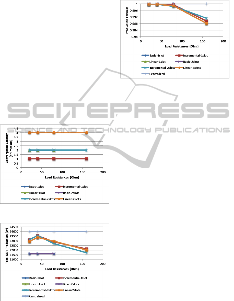
Figure 2: Convergence latency with line resistances of 0.1
Ω.
Figure 3: Total DER production with line resistances of
0.1 Ω.
Figure 4: Production fairness with line resistances of 0.1
Ω.
The convergence latency, total DER production
and fairness as functions of the value of load
resistances, are depicted for the short feeder scenario
in Figure 2, Figure 3 and Figure 4, respectively.
Four values of load resistance were considered: 20
Ω, 40 Ω, 80 Ω and 160 Ω. Different algorithm
configurations are labelled with the name of the
algorithm, followed by the number of timeslots that
an iteration comprises.
In this scenario, the load is able to sink most of
the injected DER power in all configurations.
Potential voltage limit violations will only arise for
load resistance values of 160 Ω. This is the only
place where the basic connect/disconnect scheme
will not converge. All other algorithm configurations
converge within a single iteration. The differences in
latency are thus due to the different iteration lengths.
As expected, the highest latency belongs to the
linear-2slot configuration, with the linear-1slot
latency being the same as that of the incremental-
2slot configuration.
Regarding the total DER production, the
performance is very similar in all converging
settings. As expected, the maximum value is
achieved by the centralized algorithm, followed by
the incremental and linear algorithms. The lowest
performance is presented by the basic
connect/disconnect scheme. It should be noted that
the incremental and linear algorithm configurations
present a trend to gradually reduce the DER
production as the value of load resistance increases.
The production fairness approaches the
maximum of 1.0 in all configurations. Again, a
slight reduction is observed for the incremental and
linear algorithms, when the load resistance increases
beyond 80 Ω.
For the longer feeder scenario, the metrics are
depicted in Figure 5, Figure 6 and Figure 7. This
VoltageControlwithLocalDecisionsinLowVoltageDistributionGridswithDERPenetration
171
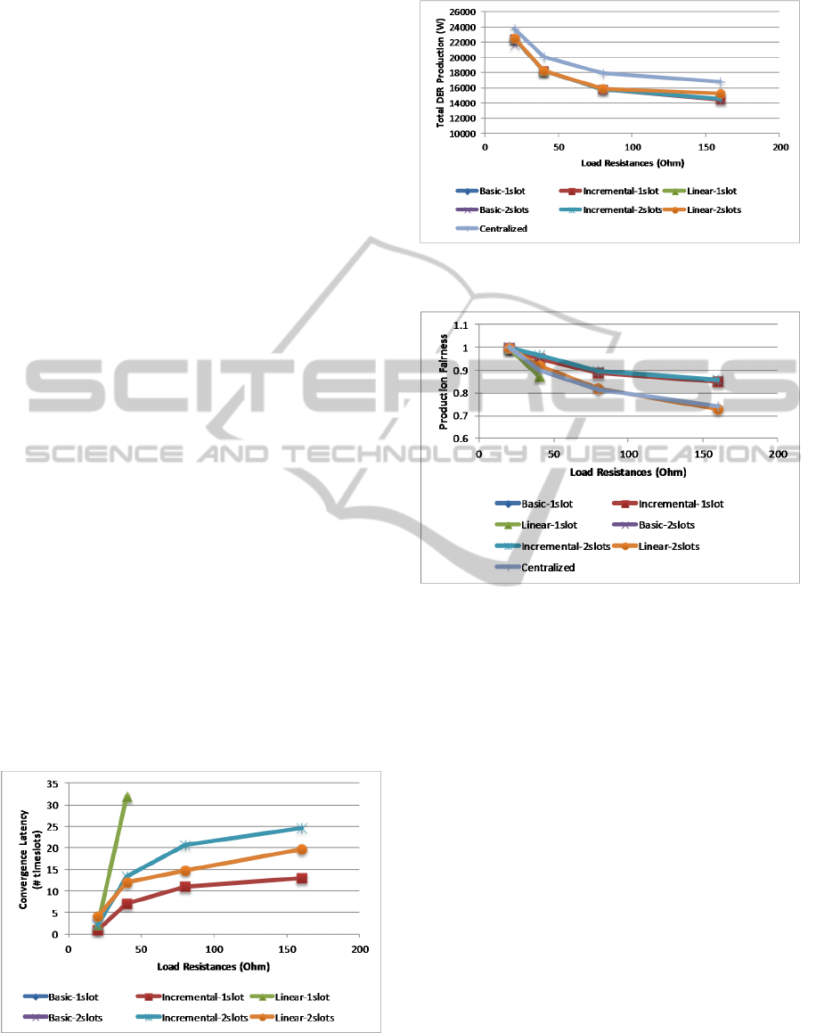
scenario is more challenging, which is illustrated by
the fact that the basic connect/disconnect scheme
only converges for the lowest value of load
resistance (20 Ω). As the load resistance increases,
the convergence latency also increases. The linear-
1slot configuration only converges for 20 Ω and 40
Ω, where it presents the highest values. This is due
to conflictual decisions between different LCs when
a single timeslot is used. The latency is lower for the
linear-2slot configuration, which is lower than that
of incremental-2slots. However, incremental-1slot
presents the lowest latency. Total DER production
and fairness present very similar curves in all
converging configurations, which only slightly
depart from the values achieved by the centralized
algorithm. Again, production and fairness tend to get
worse as the value of load resistance increases.
From these results, it can be concluded that the
basic connect/disconnect scheme widely employed
in commercial DER equipment will potentially lead
to convergence problems in scenarios with higher
line and load resistance, resulting in decreased DER
production efficiency. The incremental algorithm
achieves the best performance, approaching the ideal
solution found by the centralized algorithm. It can
and should be employed in a single slot
configuration. Although at first sight the linear
algorithm had the potential to converge faster, since
it allows larger variations of injected power in each
iteration, this may lead to more significant
conflictual LC decisions when employed in a single
timeslot configuration. With two timeslots, while
resolving the conflicts, it will be slower than the
incremental algorithm using a single timeslot. The
latter is more robust to LC decision conflicts, since
the LCs performs small state changes in each
decision cycle.
Figure 5: Convergence latency with line resistances of 0.2
Ω.
Figure 6: Total DER production with line resistances of
0.2 Ω.
Figure 7: Production fairness with line resistances of 0.2
Ω.
6 CONCLUSIONS
This paper has presented two distributed algorithms
that try to maximize DER production in LV
distribution grids with DER penetration, while
keeping the voltage levels within the operating
limits. The incremental algorithm performs small
changes of injected active power in each decision
cycle, while the linear algorithms changes the
injected power based in the assumption of a linear
relationship between the injected power and the
voltage level at the coupling point.
The proposed algorithms were evaluated and
compared with a state-of-the-art connect/disconnect
scheme and a centralized algorithm that makes
decisions based on knowledge about voltage and
current levels at all DER coupling points. Simulation
results show that the proposed algorithms approach
the optimal solutions obtained by the centralized
algorithm, with the incremental algorithm presenting
SMARTGREENS2015-4thInternationalConferenceonSmartCitiesandGreenICTSystems
172

faster convergence. The latter remained stable in all
tested scenarios and configurations.
As future work, the authors plan to study the impact
of communication network performance on the
centralized voltage control schemes, as well as to
define hybrid distributed/centralized algorithms.
ACKNOWLEDGEMENTS
This work was supported in part by European
Community’s Seventh Framework Programme
(FP7-SMARTCITIES-2013) under Grant 609132
(http://www.e-balance-project.eu/), in part by
national funding from QREN through the
“Monitorização e controlo inteligente da rede de
Baixa Tensão” (Monitor BT) project and in part by
FCT – Fundação para a Ciência e a Tecnologia, with
reference UID/CEC/50021/2013.
REFERENCES
DL 153/2014, 20th of October, by which the distributed
electricity generation activity is regulated.
Krushna, K., Kumar, S.V., 2012. Three-Phase Unbalanced
Radial Distribution Load Flow Method. International
Refereed Journal of Engineering and Science (IRJES),
ISSN (Online) 2319-183X, (Print) 2319-1821 Volume
1, Issue 1, pp.039-042.
Nunes, M., 2014. Dynamic control method of power
injected into the power grid for micro and mini
producers for voltage regulation, PT107831 INPI,
Patent submitted in August 2014, Lisbon.
Sajadi, A., Sebtahmadi, S., Koniak, M., Biczel, P.,
Mekhilef, S., 2012. Distributed control scheme for
voltage regulation in Smart Grids. International
Journal of Smart Grid and Clean Energy (SGCE),
ISSN (Online) 2373-3594, (Print) 2315-4462, Vol. 1,
No. 1, pp. 53–59.
Samadi, A., Shayesteh, E., Eriksson, R., Rawn, B., Soeder,
L., 2014. Multi-objective coordinated droop-based
voltage regulation in distribution grids with PV
systems. Renewable Energy, Elsevier, 71, 2014, pp.
315-323.
Silva, N., Delgado, N., Costa, N., Bernardo A.,
Carrapatoso, A., 2012. Control architectures to
perform voltage regulation on low voltage networks
using DG. In CIRED 2012 Workshop, Integration of
Renewables into the Distribution Grid, ISBN: 978-1-
84919-628-4, Lisbon, pp. 1-4.
Tonkosky, R., Lopes, L., El-Fouly, T., 2011. Coordinated
Active Power Curtailment of Grid Connected PV
Inverters for Overvoltage Prevention. IEEE
Transactions on Sustainable Energy, Vol. 2, No. 2,
April 2011, pp. 139-147.
U.S. Department of Energy, 2012. Application of
Automated Controls for Voltage a Reactive Power
Management.
VoltageControlwithLocalDecisionsinLowVoltageDistributionGridswithDERPenetration
173
