
Accurate Detection and Visualization of 3D Shape Deformation
by using Multiple Projectors
Masayasu Yoshigi, Fumihiko Sakaue and Jun Sato
Nagoya Institute of Technology, Gokiso, Showa, Nagoya, Japan
Keywords:
Shape Deformation Detection, Projector-projector Systems, Object Deformation Visualization, Super-
resolution.
Abstract:
In this paper, we propose a method for detecting the deformation of object shape by using multiple projectors.
In this method, a set of specially coded patterns are projected onto a target object from multiple projectors.
Then, if the target object is not deformed, the object is illuminated by plain white color, and if the object is
deformed, it is illuminated by radical colors. Thus, we can visualize and detect the deformation of object just
by projecting lights from multiple projectors. The proposed method uses the disparities of multiple projectors,
and thus, we do not any complicated method for detecting object shape deformation. In addition, we utilize
image super-resolution technique for object deformation visualization, so that we can visualize extremely
small deformation easily.
1 INTRODUCTION
Object shape measurement is very important in many
fields such as industry, 3D event detection and so on.
In particular, 3D shape reconstruction is the most im-
portant challenge in the field of computer vision. In
ordinary cases, stereo camera systems composed of
multiple cameras are used for 3D object measure-
ment. In this method, several images are taken by
multiple cameras, and 3D shape are estimated from
the set of images (Hartley and Zisserman, 2000). By
using this reconstructed 3D information, many kinds
of applications such as event detection are done.
For this purpose, the projector-camera (active
camera) systems are also used for 3D shape mea-
surement in recent years. For example, the Mi-
crosoft Kinect is used for various kinds of applica-
tions. In these method, a specific pattern is projected
from the projector to the scene, and is observed by
a camera. Then, we can reconstruct 3D shape from
the relationship between projected patterns and ob-
served images. In many cases, 3D reconstruction
from projector-camera systems is more stable and ac-
curate than that from ordinary multiple camera sys-
tems, since the projector-camera systems can project
corresponding points explicitly and extraction of cor-
responding points is much easier and denser than the
ordinary stereo camera systems.
In recent years, a projector-projector system was
also proposed for visualizing 3D information of ob-
jects (Sakaue and Sato, 2011). In this method, mul-
tiple patterns projected from multiple projectors are
combined physically on the surface of object, and
the combined lights on the object surface represent
the 3D information of the object. This method uses
the disparity of multiple projector images efficiently
for visualizing the 3D information just by project-
ing coded lights from projectors. For example, it
can visualize 3D information such as the distance
from the projector to the object and the height of ob-
ject by using color as shown in Fig.1. This method
does not require 3D measurements from sensing sys-
tems, and thus it does not need any sensing devices
such as cameras and sensing costs of computer. The
projector-projector system also enables us to avoid
system delays caused by sensing and computation,
since it does not need any sensing and computation
for obtaining 3D information and visualizing it. This
is a very big advantage for industrial applications, and
hence several methods have been proposed based on
this framework(R. Nakamura, 2010; S. Takada, 2014;
K. Suzuki, 2013). In addition, we can obtain 3D infor-
mation easily just taking the scene by using the cam-
era devices and just simple image processing such as
color detection.
However, unfortunately these methods cannot vi-
sualize detail structure of the scene because of the
limit of projector resolution. Thus, we in this pa-
577
Yoshigi M., Sakaue F. and Sato J..
Accurate Detection and Visualization of 3D Shape Deformation by using Multiple Projectors.
DOI: 10.5220/0005455405770582
In Proceedings of the 10th International Conference on Computer Vision Theory and Applications (MMS-ER3D-2015), pages 577-582
ISBN: 978-989-758-090-1
Copyright
c
2015 SCITEPRESS (Science and Technology Publications, Lda.)
(a) Distance visualization (b) Height visualization
Figure 1: Distance visualization by projector-projector sys-
tem. In figure(a), objects are colored by red, yellow and
green when objects are arranged near, middle and far from
projectors, respectively. In figure(b), height from floor is
visualized by green, yellow and red.
Figure 2: 3D structure visualization by using projection
from multiple projectors.
per propose a new projector-projector coordination
method, which enables us to visualize very tiny de-
formation of object shape just by projecting images
from multiple projectors. For this objective, we use
more than 3 projectors, and realize super-resolution
visualization of object deformation.
2 OBJECT EMPHASIS BY USING
MULTIPLE PROJECTORS
2.1 Object Shape Emphasis
We first introduce the detail of object shape emphasis
using multiple projectors. Nakamura et al.(R. Naka-
mura, 2010) proposed 3D structure visualization us-
ing multiple projectors. By using their method, we
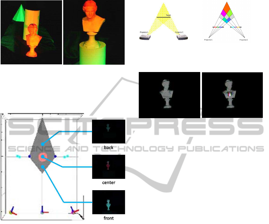
(a) Target surface
(b) Projection result
Figure 3: Visualization of surface deformation from 2 pro-
jectors.
(a) without deformation
(b) with deformation
Figure 4: Visualization of surface deformation from 2 pro-
jectors.
can visualize arbitrary 3D structure just by projecting
specific images from multiple projectors. We summa-
rize their method in this section.
Let us consider the case where we visualize the
3D space as shown in Fig.2. In this case, an object
situated at the center of the region is colored by red,
and an object situated at the other regions is colored
by white. In this case, the object position is visualized
by colors, and thus we can catch the 3D position of the
object intuitively. Figure 2 shows the result of visu-
alized position by their method. As shown in Fig. 2,
the object is colored by red when it exists at the center
region, and it is colored by white when it exists at the
other region.
2.2 Object Deformation Visualization
The 3D structure visualization described in the previ-
ous section can be extended to visualization of arbi-
trary 3D structures if we can use infinite number of
projectors. However, we can use limited number of
projectors in reality, and thus, we cannot visualize ar-
bitrary 3D structure. This is because projected images
from projectors are 2-dimensional images, while the
object has 3-dimensional structure in general.
In order to avoid this problem, Takada et
al.(S. Takada, 2014) proposed a method for empha-
sizing 3D surface just by using 2 projectors. In their
method, they focused not on 3D structure but on 3D
surface. In this case, we only need to consider pro-
jected pattern on a 2-dimensional curved surface, and
thus we can emphasize object surface by using only 2
projectors. Figure 3 shows the basic principle of this
VISAPP2015-InternationalConferenceonComputerVisionTheoryandApplications
578
Figure 5: Image super-resolution by superimposed images.
method. The object shown in Fig. 3 (a) is illuminated
by a set of projectors. Then, 2 images projected from
2 projectors are combined on the object surface. The
projected images has complementary colors, e.g. red
and cyan, at a pair of corresponding pixels. Then, the
combined color at the object surface becomes white
when the target object is at the calibrated position. If
the object surface is deformed or moved from the cal-
ibrated position, the pair of corresponding pixels of 2
projectors changes, and thus the observed color also
changes as shown in Fig.3 (b). Thus, we can visual-
ize the changes in object shape by using the changes
in projected colors on the object surface.
The method can visualize object deformation just
by projecting specific patterns from multiple projec-
tors. However, the accuracy of visualization strongly
depends on the resolution of projected images. There-
fore, we need high resolution projectors if we want
to visualize small deformation of object shape. How-
ever, the resolution of projectors is determined by dis-
play devices such as DLP and LCD, and thus their
resolution is physically limited.
3 SUPER-RESOLUTION OF
PROJECTED IMAGES
In order to improve the resolution of projected im-
ages, image super-resolution using multiple projec-
tors were invented in recent years (Venkata and
Chang, 2007). In this method, multiple images are
projected from multiple projectors to the same area of
the screen simultaneously as shown in Fig.5. The pro-
jected images have sub-pixel shift as shown in this fig-
ure. Thus, we can represent higher resolution images
by controlling the sub-pixel information efficiently.
Let us consider image projection for image super-
resolution. The image projection from each projector
is described by a linear equation as follows:
y = A
i
x
i
(1)
where y indicates a vector which consists of the com-
ponents of an M
′
× N
′
high resolution image, x
i
indi-
cates a vector which consists of the components of an
M × N low resolution image projected from i-th pro-
jector and A
i
indicates a projection matrix from the
i-th projector. The j-th column of A
i
represents the
PSF (Point Spread Function) of j-th pixel of the i-th
projector. Thus, the projected image y consists of a
weighted sum of the PSF.
From Eq.(1), the evaluation function for image su-
per resolution can be described as follows:
E = ||y−
∑
i
A
i
x
i
||
2
(0 ≤ x
i
≤ I
max
) (2)
where I
max
is the maximum intensity which can
be projected from the projector. By estimating x
i
which minimize E in Eq.(2) and projecting them from
the multiple projectors, we can generate a super-
resolution image from superimposed images.
By using the above method, we can utilize higher
resolution projectors virtually, even if we use only
low resolution projectors. Furthermore, the projec-
tion surface is not limited to a planar surface. If
we compute the PSF matrix A
i
on a curved surface,
the super-resolution images can be generated even
on the curved surface. This means the image super-
resolution can be achieved in the visualization of ob-
ject surface deformation, and we can visualize the
change in shape more precisely, even if we use low
resolution projectors.
4 SUPER-RESOLUTION OF
SHAPE DEFORMATION
VISUALIZATION
4.1 Visualization of Shape Deformation
with Image Super-resolution
Let us consider a method for achieving accurate vi-
sualization of object surface deformation by using a
set of low resolution projectors. The simplest way
to achieve high resolution visualization of surface de-
formation is to compose 2 sets of virtual high reso-
lution projectors, each of which is composed of a set
of low resolution projectors. However, this is not the
most efficient way to improve the accuracy of surface
deformation visualization, since we can only utilize
sub-pixel information of each virtual projector. If we
use sub-pixel information generated by all projectors,
we may be able to visualize object surface deforma-
tion more accurately. Thus, instead of considering the
relationship among a set of projectors in a single vir-
tual projector, we consider the relationship among all
AccurateDetectionandVisualizationof3DShapeDeformationbyusingMultipleProjectors
579

projectors used for visualizing object surface defor-
mation, and derive the most efficient projection pat-
terns of these projectors for improving the accuracy
of surface deformation visualization.
4.2 Efficient Super-resolution
Visualization
In order to realize accurate surface deformation visu-
alization, we define an evaluation function of projec-
tion patterns.
In the surface deformation visualization, we gen-
erate projection patterns, so that the object is colored
by white if there is no deformation, and is colored by
the other colors if there exist surface deformations.
Thus, for evaluating the whiteness of object surface
with original shape, we define the following evalua-
tion function:
E
s
= ||w−
∑
i
A
i
x
i
||
2
(0 ≤ x
i
≤ I
max
) (3)
where w is a super-resolution white color pattern on
the object surface. By minimizing E
s
, we can observe
white color on the original object surface. Note that
the white color on the object surface is not necessar-
ily composed of the projection of white color, and it
can be composed of the projection of various colors
from multiple projectors. Also, basis white color on
the original object shape can be changed to arbitrary
colors if we want. For example, we can add shad-
ing information to the basis white color such that the
surface is illuminated by a single light source, which
is useful for visualizing 3D information of original
surface shape. If we use truly white color in Eq.(3),
shading information of object surface disappears.
We next consider the evaluation function for visu-
alizing the deformation of object surface. For accu-
rate surface deformation visualization, the object sur-
face color should be changed drastically when object
shape is changed. The change in color can be rep-
resented by the derivative of the observed color, and
then the derivative should be as large as possible for
efficient deformation visualization. Since the deriva-
tive of the observed color depends on the color of
projected images, the derivative of projected images
should be as large as possible for efficient surface de-
formation visualization. Thus, we define the second
evaluation function as follows:
E
d
= ||
∑
i
D
x
x
i
||
2
+ ||
∑
i
D
y
x
i
||
2
(0 ≤ x
i
≤ I
max
) (4)
where D
x
and D
y
indicate the derivative operators in
horizontal and vertical directions. By maximizing
E
d
, the image derivatives become large. Note that,
corresponding points among projector images are on
epipolar lines defined by arbitrary two projectors, and
the change in corresponding points caused by the
deformation of object shape occurs on the epipolar
lines. Therefore, the derivatives along the epipolar
lines are important for visualizing the shape deforma-
tion. For example, if the epipolar lines are parallel
to the horizontal axis, we only need to consider hor-
izontal derivatives. Thus, the horizontal and vertical
derivatives in Eq.(4) can be replaced by directional
derivatives along with the epipolar lines.
Since we want to derive projection images so that
they minimize E
s
and maximize E
d
, we define the
evaluation function for visualizing object shape de-
formation as follows:
E
c
= wE
s
− (1− w)E
d
(5)
where w is a weight. By minimizing E
c
, we can ob-
tain optimized projection images of multiple projec-
tors for visualizing object surface deformation.
5 EXPERIMENTS
5.1 Environment
We evaluated the proposed method by using multi-
ple projectors. We used 3 projectors as shown in
Fig.6. The resolution of these projected images are
50 × 50. The projector images are projected onto a
target object shown in Fig.7. The object was situ-
ated in front of the projectors. The PSF in projection
matrices A
i
were measured at each pixel on this ob-
ject. Figure 8 shows examples of the measured PSF.
In this experiment, color images were used, and thus,
PSF for red, green and blue were measured respec-
tively. In these figures, the bottom left region shows
resized PSF. Note, the resolution of a camera image is
much higher than the resolution of projector images.
Thus, the measured PSF is spread over some pixels in
these images. By using the PSF, the projection images
for visualizing object surface deformation were com-
puted. The computed images for each projector are
shown in Fig.9. For comparison, projection images
for not only 3 projectors, but also 2 projectors were
computed. These images were projected onto the tar-
get object simultaneously from multiple projectors.
5.2 Results
Figure10 shows illuminated results when the target
object was situated at the original position. As shown
in this figure, although the target object was slightly
VISAPP2015-InternationalConferenceonComputerVisionTheoryandApplications
580
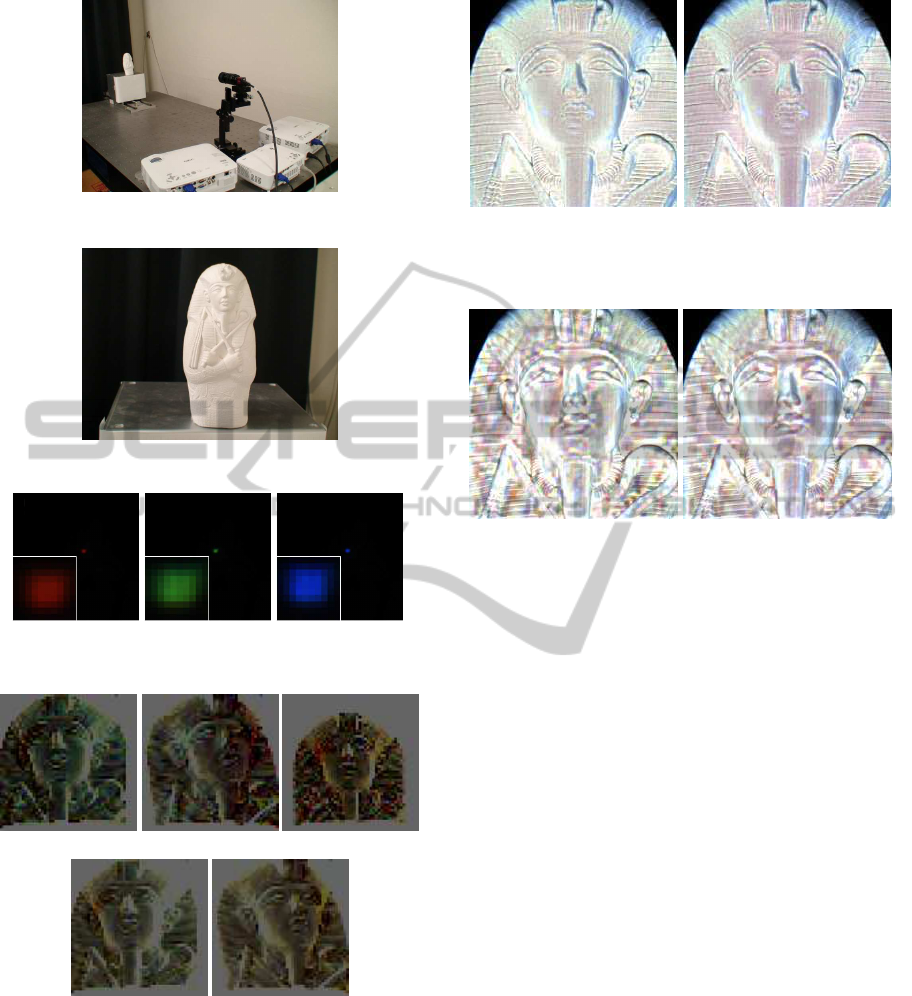
Figure 6: Experimental Environment.
Figure 7: Target object.
(a) PSF (Red) (b) PSF (Green) (c) PSF (Blue)
Figure 8: Examples of measured PSF.
(a) Projected images for 3 projectors.
(b) Projected images for 2 projectors.
Figure 9: Images projected by 3 projectors and 2 projectors.
colored, the object was observed as it is illuminated
by an ordinary single white light source. In particu-
lar, the result projected by 3 projectors is more close
to white and better, since the projected images can ap-
proach to ideal result by using larger number of pro-
jectors.
We next translated the object with 3 mm. This ob-
ject translation indicates whole shape deformation of
(a) by 3 projectors (b) by 2 projectors
Figure 10: Observed results when the object was situated at
the original position.
(a) by 3 projectors (b) by 2 projectors
Figure 11: Observed results when the object was moved
from the original position.
the target object. The observation result is shown in
Fig.11. As shown in this figure, the appearance of the
target object was drastically changed, and the object
was colored by various colors. These results show
that the proposed method can visualize the change in
object surface accurately. In addition, we can detect
object shape deformation by using simple image pro-
cessing method such as color detection.
From the comparison of results of 2 projectors and
3 projectors in Fig.11 (a) and (b), we find that larger
change in appearance occurs in 3 projectors than in 2
projectors. The result indicates that we can visualize
the deformation of object shape more efficiently and
accurately by using larger number of projectors.
5.3 Evaluations
We next evaluate the accuracy of the proposed
method. In this experiment, target object was moved
step by step, and the change of appearance was eval-
uated at each distance. An object shown in Fig 7 was
used as a target object. For comparison, the target ob-
ject was illuminated by 2 different projector systems,
that is 2 projector system and the proposed 3 projec-
tor system.
Figure 12 shows the changes in appearance in the
2 projector system and the 3 projector system re-
AccurateDetectionandVisualizationof3DShapeDeformationbyusingMultipleProjectors
581

spectively. In this figure, the horizontal axis shows
the magnitude of object motion and the vertical axis
shows the RMS difference of intensity from that at the
original position. As shown in this figure, when we
use the 3 projector system, the change in appearance
is larger than that of the 2 projector system. From
these results, we find that the proposed method can
visualize object surface deformation more efficiently
and accurately.
Figure 12: Relationship between object motion and change
in appearance.
6 CONCLUSIONS
In this paper, we proposed a method for visualiz-
ing/detecting the deformation of object surface by
using the disparity in multiple projector images, in
which the deformation of object surface is visualized
by color information. In order to visualize the small
shape deformation accurately, we utilized the image
super-resolution technique. By using the proposed
method, we can use the sub-pixel information of pro-
jected images efficiently, and can visualize extremely
small object deformation accurately. The experimen-
tal results show that our method can visualize small
shape deformation more accurately than the existing
method. The proposed method does not require com-
puters nor cameras for visualizing the deformation
of object surface once the projector system was cal-
ibrated. Thus, the proposed method is very useful for
many industrial applications such as defect inspection
in factory automation and 3D event detection.
REFERENCES
Hartley, R. and Zisserman, A. (2000). Multiple View Geom-
etry in Computer Vision. Cambridge University Press.
K. Suzuki, F. Sakaue, J. S. (2013). 3d invariants from coded
projection without explicit correspondences. In Proc.
International Conference on Computer Vision and Ap-
plications(VISAPP2013), pages 286–293.
R. Nakamura, F. Sakaue, J. S. (2010). Emphasinzing 3d
structure visually using projection from multiple pro-
jectors. In Proc. Asian Conference on Computer Vi-
sion, pages 619–632.
S. Takada, F. Sakaue, J. S. (2014). 3d object empha-
sis using multiple projectors. In International Con-
ference on Computer Vision Theory and Applica-
tions(VISAPP2014).
Sakaue, F. and Sato, J. (2011). Surface depth computa-
tion and representation from multiple coded projector
light. In Proc. International Workshop on Projector-
Camera Systems(PROCAMS2011), pages 75–80.
Venkata, N. and Chang, N. (2007). Realizing super-
resolution with superimposed projections. In Proc.
International Workshop on Projector-Camera sys-
tems(Procams), pages 1–8.
VISAPP2015-InternationalConferenceonComputerVisionTheoryandApplications
582
