
Automatic Obstacle Classification using Laser and Camera Fusion
Aurelio Ponz
1
, C. H. Rodríguez-Garavito
2
, Fernando García
1
, Philip Lenz
3
,
Christoph Stiller
3
and J. M. Armingol
1
1
Intelligent Systems Lab, Universidad Carlos III De Madrid, Butarque, 15, Leganés, Madrid, Spain
2
Automation Engineering Department, Universidad de La Salle, Bogotá, Colombia
3
Institut für Mess- und Regelungstechnik, Karlsruher Institut für Technologie, Karlsruhe, Germany
Keywords: Computer Vision, Lidar, Advanced Driving Assistance System, Sensor Fusion.
Abstract: State of the art Driving Assistance Systems and Autonomous Driving applications are employing sensor
fusion in order to achieve trustable obstacle detection and classification under any meteorological and
illumination condition. Fusion between laser and camera is widely used in ADAS applications in order to
overcome the difficulties and limitations inherent to each of the sensors. In the system presented, some
novel techniques for automatic and unattended data alignment are used and laser point clouds are exploited
using Artificial Intelligence techniques to improve the reliability of the obstacle classification. New
approaches to the problem of clustering sparse point clouds have been adopted, maximizing the information
obtained from low resolution lasers. After improving cluster detection, AI techniques have been used to
classify the obstacle not only with vision, but also with laser information. The fusion of the information
acquired from both sensors, adding the classification capabilities of the laser, improves the reliability of the
system.
1 INTRODUCTION
About 1.2 million people die every year in the world
as a consequence of traffic accidents (WHO, 2009).
ADAS use widely lasers and cameras to detect and
classify obstacles on the road. These sensors are
complementary, as the laser’s ability to detect
obstacles regardless of the light quality and to select
Regions of Interest (ROI) for camera classification,
improves remarkably the speed and accuracy of the
CV classification in the images from the camera.
The present work has been developed using the
Intelligent Vehicle based on Visual Information 2.0
(IVVI 2.0) (Figure 1), the Intelligent Systems Lab’s
research platform (Martín et al., 2014).
The article is divided in the following sections:
Section 2 provides scientific context of the state of
the art in the related domain. Section 3 is a general
description of the system. Section 4 describes the
method for laser point cloud (PC) clustering, which
is the initial part of obstacle detection. Section 5
outlines the data alignment process, essential for a
correct data association between the camera and the
laser system. Section 6 depicts the strategy for
obstacle classification with a Support Vector
Machine (SVM). Finally, conclusions for the present
work are presented.
2 RELATED WORK
The work described in the present paper covers
several fields with interesting state of the art.
Regarding the automatic and unattended data
alignment phase in our system, (Li et al., 2011)
proposed a method for calibration using a
chessboard pattern, (Rodríguez-Garavito et al.,
2014) proposed a method for automatic camera and
laser calibration, based on PC reconstruction of the
road surface. Other approaches such as (Li et al.,
2011) and (Kwak et al., 2011) projects the features
into a 2D plane to minimize the distance among the
features in the different sensors. (Lisca et al., 2010)
presents a CAD model based calibration system for
inter-sensor matching. Similar approach based on
triangular model is presented in (Debattisti et al.,
2013) and based on circular models in (Fremont and
Bonnifait, 2008).
Data fusion detection approaches can be divided in
centralized and decentralized schemes. Some
examples of decentralized schemes can be found in
(Premebida et al., 2009) and (Premebida et al., 2010)
with different algorithms to combine the features
from computer vision and laser , such as Naïve
Bayes, GMMC, NN, FLDA. Decentralized schemes
19
Ponz A., H. Rodríguez-Garavito C., García F., Lenz P., Stiller C. and M. Armingol J..
Automatic Obstacle Classification using Laser and Camera Fusion.
DOI: 10.5220/0005459600190024
In Proceedings of the 1st International Conference on Vehicle Technology and Intelligent Transport Systems (VEHITS-2015), pages 19-24
ISBN: 978-989-758-109-0
Copyright
c
2015 SCITEPRESS (Science and Technology Publications, Lda.)
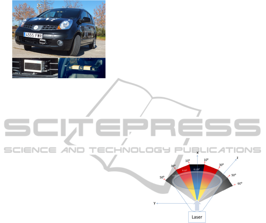
Figure 1: IVVI 2.0 research platform.
implements detection and classification on each
sensor independently and a further fusion stage
combines the detection according to the certainty
provided by each sensor. (Spinello and Siegwart,
2008) provides high level fusion based on
multidimensional features for laser and Histogram of
Oriented Gradients (HOG) for computer vision.
(García et al., 2012) provides pedestrian detection
based on pedestrian's leg model for laser and HOG
features for computer vision for distributed
pedestrian detection and danger evaluation. (García
et al., 2014) takes advantage of advance fusion
techniques (i.e. Joint Probabilistic Data Association
Filter) to enhance decentralised pedestrian detection.
3 GENERAL DESCRIPTION
This work is included in the IVVI 2.0 project
(Figure 1). IVVI 2.0 is the second platform for
development and research of ADAS technologies of
the Intelligent Systems Lab, at Universidad Carlos
III de Madrid.
In the presented application, a Sick LDMRS 4-
layer Laser and a stereo camera are used. Laser for
primary obstacle detection and later for
classification and stereo capability from the camera
is used for PC ground representation and data
alignment parameters estimation; later one of the
cameras is used for image capturing.
The laser generates a PC from which the system
extracts the obstacles as clusters of points. These
clusters are used both for ROI generation in the
images and as information for obstacle
classification. The extracted ROIs in the image are
processed for obstacle classification using AI
methods applied to CV. The last step in the process
performs further information fusion between laser
and camera for a final obstacle classification based
on machine learning.
4 POINT CLOUD CLUSTERING
FOR LASER DETECION
The first step in our system is the obstacle detection
using laser generated PCs. The laser obtains a PC
representing some of the reality in front of the
vehicle. Obstacles are part of this reality and can be
located as local concentrations of points in the PC
that can be mathematically categorized as clusters.
Several clustering techniques have been studied in
order to obtain the highest and most reliable amount
of information from the PC. It is important to note
that obstacles to be detected will be represented by
very few points in the PC, typically from four points
to not much more than fifty depending on the
distance to the vehicle, due to laser limitations. Most
of the clustering strategies already available are
designed for highly populated PC, obtained from
high definition multilayer laser scanners or stereo
cameras, and do not adapt well to our outdoor,
sparse PCs offering limited information.
Figure 2: Angular resolutions by sector in the laser.
Maximum resolution front, minimum in the sides.
4.1 Adapted Euclidean Distance and
Geometrically Constrained
Clusters
In this approach, a classical Euclidean distance
clustering strategy has been adopted, modulated by
several parameters in order to modify the clustering
behaviour, such as distance from the sensor to the
obstacle, geometrical constraints, allowed number of
points in every cluster, etc.
In this approach, clusters are defined as the set of
points separated a distance variable as a function of
several parameters, plus some points meeting some
geometric constraints, such as belonging to the same
line in the space than some of the points in the
cluster.
The strategy is defined as an iterative addition of
points to the cluster with the following steps:
VEHITS2015-InternationalConferenceonVehicleTechnologyandIntelligentTransportSystems
20
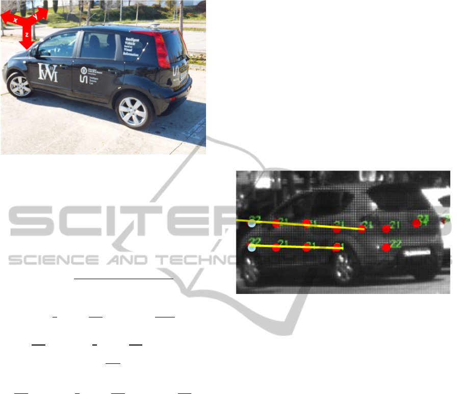
Figure 3: Axis representation: X=laser-obstacle distance,
Z=detection height, Y=horizontal deviation.
First point in the PC is taken as the first point in
the cluster.
All the other points in the PC are checked to
have a distance smaller than the cluster threshold
ClusterTh
ℎ=ℎ+
(
)
(
)
=
(
)
+
(
(
)
)
if
2
10
360
then
=2π
0.125
360
if2π
10
360
2
30
360
then
=2π
0.25
360
if2π
30
360
2
60
360
then
=2π
0.5
360
(1)
where x,y,z are point’s coordinates. Due to laser
restrictions,
is always 0.8º, BaseTh is a parameter
experimentally determined as the base threshold.
DistCorr(x) is a function of the x coordinate which
ensures that no distance smaller than the minimum
physically possible distance will be required, as seen
in Equation (1), and depending on the different
angular resolutions seen in Figure 2. DistCorr(x) is
computed as the minimum distance possible
between two consecutive points in z and y
coordinates.
Represents the angle between two
consecutive laser reads in horizontal (y axis) and
is the angle between two consecutive laser reads
in vertical (z axis).
All the points in the PC are checked for cluster
inclusion. The same iteration is performed for every
point added to the cluster until all cross checks are
performed. Then, points close to the obstacle but not
belonging to the cluster are included into a
temporary new PC together with the obtained
cluster, and then lines are searched in the new
cluster using RANSAC. If lines are found containing
a determined minimum of points belonging to the
original cluster and points not belonging to it, then
these points are added to the cluster. This strategy
has proven to be effective for oblique obstacles.
Figure 4 shows the result of the algorithm. Red
dots are the cluster created by Euclidean Adapted
distance. Blue dots are the points close to the cluster
but not belonging to it. Yellow lines are 3D lines
found by RANSAC, including points from the
original cluster and points from the extended cluster.
Figure 4: Extended cluster. Blue points are added to the
cluster as they share a line with points in the cluster.
Upon completion of cluster extraction, it is
checked against the parameters ClusterTolerance for
maximum width of cluster in meters, and
minClusterSize and maxClusterSize for minimum
and maximum number of points, respectively. These
parameters are also a function of the distance to the
obstacle.
The strategy is addressed to obtain the most
populated clusters possible, taking into account that
we are using a low resolution multilayer laser. The
threshold distance must be adapted to the distance x
from the laser sensor to the obstacle, as the distance
between consecutive laser points grows with x. Due
to laser construction limitations, the minimum
distance detected in y and z in consecutive points
will be greater than the initial threshold if not
adapted following Equation (1).
4.2 Ground Detection and Removal
from Point Cloud
As outlined in Section 5, our system can compute
the plane corresponding to the road surface, so it is
possible to remove ground plane points from the list
of detected clusters.
AutomaticObstacleClassificationusingLaserandCameraFusion
21
5 DATA ALIGNMENT
Our system is based in data fusion between several
sensors, based on different physical phenomena.
Thus each of these sensors has its own system of
reference, and extrinsic parameters between sensors
system of reference must be estimated in order to
perform the data alignment.
To achieve the necessary alignment, rotation and
translation between sensors must be estimated. Some
methods have already been proposed by other
authors, involving chessboards or specific patterns
(Li et al., 2007) detectable by all of the sensors
involved in the fusion (Kwak et al., 2011). This is
cumbersome and requires driver implication or some
help from others, needs specific and stationary
environment and to be performed manually again in
case of change of orientation or translation between
sensors.
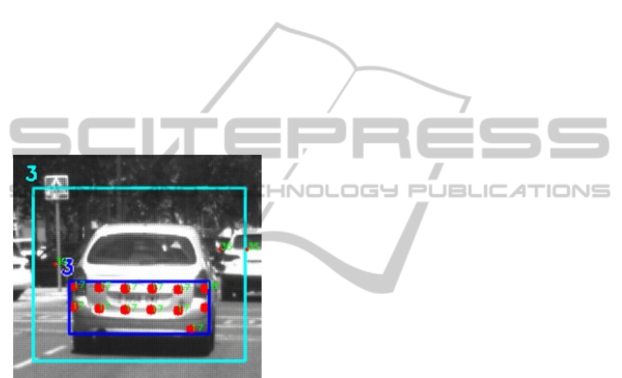
Figure 5: Obstacle detection based on cluster computation.
Dark blue is the cluster, cyan is the ROI for vision
classification.
Our approach estimates the extrinsic parameters
of all the sensors involved, and calibration between
them, assuming flat surface in front of the vehicle,
thus sensor’s height and two rotation angles can
already be determined. For the third angle
computation, any identifiable obstacle located in the
road surface can be used.
Applying the M-estimator-Sample-Consensus
(MSAC) algorithm for plane detection in the PCs
obtained from the stereo camera and from the laser,
the most populated planes are found from the clouds
in the form
(
)
:
+
+
+=0
(2)
which can be written in the Hessian form
(
)
:
.p
=ℎ
(3)
where
is the vector normal to the road plane, and
the relation between this vector and the camera and
laser rotation angles can be computed as in
(Rodríguez-Garavito et al., 2014).
Once all the calibration parameters, i.e. roll,
pitch, yaw and x,y,z translations between sensors
have been computed, the system is able to translate
from laser coordinates into camera coordinates in the
image for obstacle classification using Computer
Vision.
The conversion between laser and image
coordinate systems can be performed as in equation
(4):
=(
+)
=
cos
(
)
0()
0 1 0
−() 0 ()
·
1 0 1
0()−()
0 () ()
·
cos
(
)
−sin
(
)
0
() () 0
0 0 1
,
=
,
(4)
where T represents the translation vector and R the
rotation matrix between sensors.
6 OBSTACLE CLASSIFICATION
USING LASER AND IMAGE
INFORMATION FUSION
Obstacle classification in this work can be
performed with single sensor information or using
sensor fusion information.
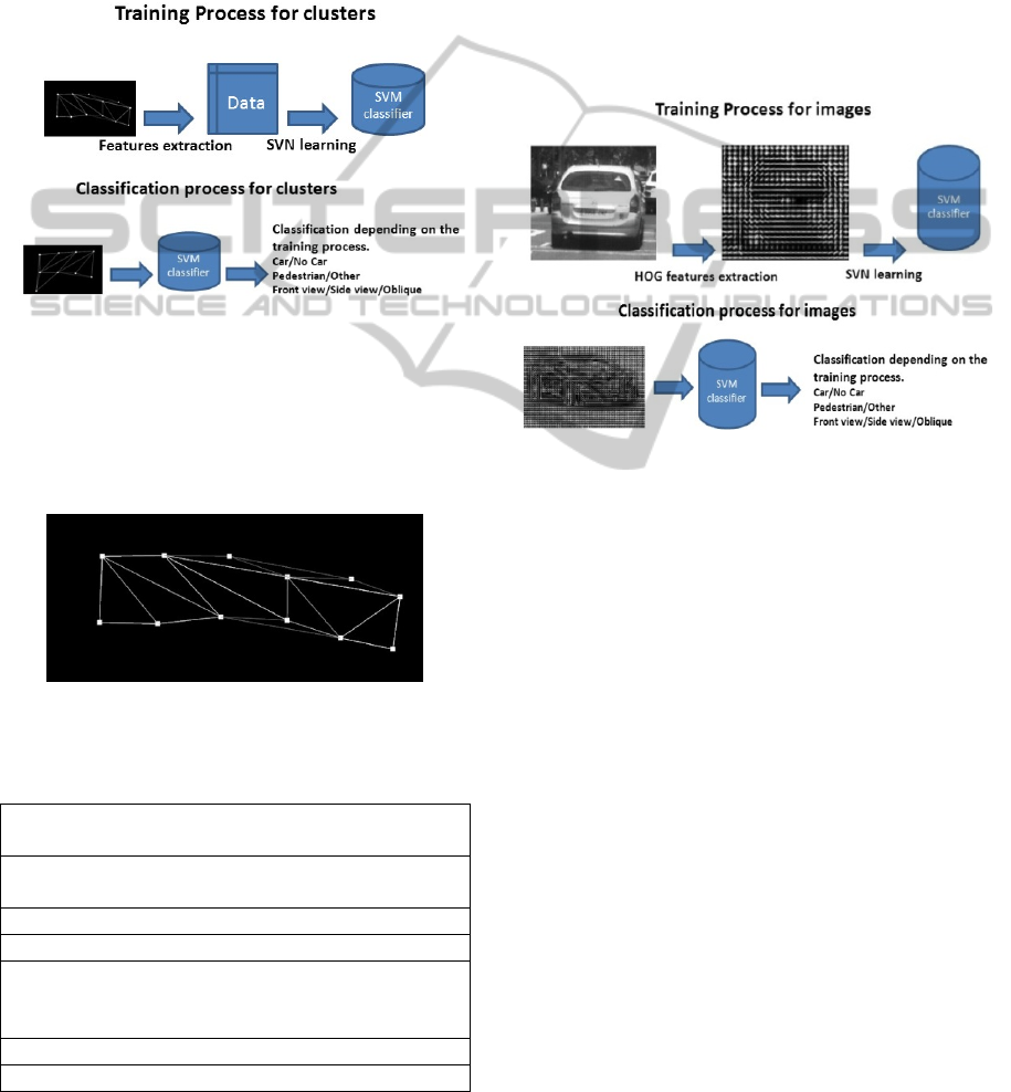
6.1 SVM Classification
Classification is performed using the SVM
implementation from the Computer Vision OpenCV
library. SVM algorithm was developed by Vapnik &
Cortes (Cortes and Vapnik, 1995) and is widely used
in machine learning. In the present work, a database
of manually labelled images and clusters is used to
execute a supervised learning process. After the
training process, the SVM structures are stored and
used for classification of images and clusters as seen
in Figure 6 and Figure 8.
VEHITS2015-InternationalConferenceonVehicleTechnologyandIntelligentTransportSystems
22
6.2 Laser Feature Vector
Clusters detected in laser generated PCs are used to
determine a ROI in the image, but can also be used
for obstacle classification without image support
(Premebida et al., 2009).
Clusters are converted into a mesh structure by
Delaunay triangulation in order to reconstruct the
shape of the obstacle, as seen in Figure 7.
Figure 6: SVM learning process for clusters: Training and
classification.
Previous works (Premebida et al., 2009) have
considered 2D PCs for classification, but the present
work is intended to extract features from a 3D PC.
The features considered are described in Table 2.
Figure 7: Mesh representation of a cluster. Triangles
represent the obstacle surface.
Table 1: Features considered for cluster classification.
Concentration: Normalized mean distance (NMD)
to the centroid 3D
Y-Z, X-Z, X-Y concentration: NMD to the
centroid excluding x,y,z
Planicity: NMD to the most populated plane
Sphericity: NMD to the most populated sphere
Cubicity: Measures how far are the planes
containing the mesh triangles from being the
same plane or from being perpendicular .
Triangularity: Measures the triangles uniformity
Average deviation from the median in x,y,z
6.3 Computer Vision Feature Vector
As pointed before, obstacles found in the Laser PC
as clusters are used to determine a ROI in the image
suitable for applying SVM for obstacle classification
in images.
These images have been manually labelled as
frontal view, back view, side view, frontal oblique
view and back oblique view. Later, Histogram of
Oriented Gradients (HOG) features are extracted
from every image, and SVM training is performed
following the process outlined in Figure 8, in order
to obtain the SVM classifier.
Figure 8: SVM learning process for images: Training and
classification.
6.4 Information Fusion
In poor illumination conditions, when the camera
offers no help, laser obstacle classification can still
be used, but the real advantage of the sensor fusion
resides in the combination of multisensor
information to obtain a result which is greater than
the mere sum of the individual contributions.
(García et al., 2014). Information fusion will be
performed with SVM and results will be compared
with individual sensor classifications.
7 PRELIMINARY RESULTS AND
DISCUSSION
The presented work is currently under development
but its results have been preliminarily tested,
showing better figures using sensor fusion for
classification than single sensor classification, as
presumed, and very promising expectations.
AutomaticObstacleClassificationusingLaserandCameraFusion
23

ACKNOWLEDGEMENTS
This work was supported by the Spanish
Government through the CICYT projects
(TRA2013-48314-C3-1-R) and (TRA2011-29454-
C03-02.
REFERENCES
Debattisti, S, Mazzei, L & Panciroli, M 2013. Automated
extrinsic laser and camera inter-calibration using
triangular targets. Intelligent Vehicles Symposium
(IV), 2013 IEEE, 2013, pp. 696–701.
Cortes, C & Vapnik, V 1995, Support vector network,
Machine Learning, vol. 20, pp. 1-25.
Fremont, V & Bonnifait, P 2008. Extrinsic calibration
between a multi-layer lidar and a camera. 2008 IEEE
Int. Conf. Multisens. Fusion Integr. Intell. Syst., 2008.
García, F, Jiménez, F, Naranjo, JE, Zato, JG, Aparicio, F,
Armingol, JM & de la Escalera, A. 2012. Environment
perception based on LIDAR sensors for real road
applications.
García, F, García, J, Ponz, A, de la Escalera, A &
Armingol, JM 2014. Context Aided Pedestrian
Detection for Danger Estimation Based on Laser and
Computer Vision. Expert Systems with Applications,
Vol: 41 (15), pp.6646-6661.
Kaempchen, N, Buehler, M & Dietmayer, K 2005.
Feature-level fusion for free-form object tracking
using laserscanner and video. IEEE Proceedings
Intelligent Vehicles Symposium 2005, pp. 453–458,
2005.
Kwak, K, Huber, DF, Badino, H & Kanade, T. 2011
.Extrinsic calibration of a single line scanning lidar
and a camera. IEEE/RSJ Int. Conf. Intell. Robot.
Syst., pp. 3283–3289, 2011.
Li, Y, Ruichek, Y & Cappelle, D 2011. 3D triangulation
based extrinsic calibration between a stereo vision
system and a LIDAR. 14th Int. IEEE Conf. Intell.
Transp. Syst., pp. 797–802, 2011.
Li, Y, Liu, Y, Dong, L, Cai, X 2007. An algorithm for
extrinsic parameters calibration of a camera and a
laser range finder using line features, IEEE/RSJ Int.
Conf. Intell. Robot. Syst.
Lisca, G, Jeong, PJP & Nedevschi, S 2010. Automatic one
step extrinsic calibration of a multi layer laser relative
to a stereo camera. Intell. Comput. Commun. Process.
(ICCP), 2010 IEEE Int. Conf., 2010.
Martín, D, García, F, Musleh, B, Olmeda, D, Marín, P,
Ponz, A, Rodríguez, CH, Al-Kaff, A, de la Escalera, A
& Armingol, JM 2014. IVVI 2.0: An intelligent
vehicle based on computational perception. Expert
Systems with Applications 41.
Premebida, C, Ludwig, O & Nunes, U 2009. LIDAR and
Vision-Based Pedestrian Detection System. Journal of
Field Robotics, vol. 26, no. Iv, pp. 696–711, 2009.
Premebida, C, Ludwig, O, Silva, M & Nunes, U 2010. A
Cascade Classifier applied in Pedestrian Detection
using Laser and Image-based Features.
Transportation, pp. 1153–1159, 2010.
Rodríguez-Garavito, CH, Ponz, A, García, F, Martín, D,
de la Escalera, A & Armingol, JM 2014. Automatic
Laser and Camera Extrinsic Calibration for Data
Fusion Using Road Plane.
Spinello, L & Siegwart, R, 2008. Human detection using
multimodal and multidimensional features. IEEE
International Conference on Robotics and Automation,
3264-3269. DOI: 10.1109/ROBOT.2009.4543708.
WHO, 2009. Global status report on road safety. Time for
action. WHO library cataloguing-in-publication data,
World Health Organization 2009, ISBN 978-9-
241563-84-0, Geneva, Switzerland.
VEHITS2015-InternationalConferenceonVehicleTechnologyandIntelligentTransportSystems
24
