
Building Multi-Robot System based on Five Capabilities Model
Atef Gharbi
1
, Dhouha Ben Noureddine
2
and Nadhir Ben Halima
3
1
National Institute of Applied Sciences and Technology, Tunis, Tunisia
2
Faculty of Science of Tunis, Tunis, Tunisia
3
College of Computer Science and Engineering, Taibah University - Yanbu Branch, Yanbu Al-Bahr, Saudi Arabia
Keywords:
Multi-Robot Systems, Five Capabilities Model, Distributed Planning, Benchmark Production System.
Abstract:
Multi-Robot System (MRS) is considered as a particular form of Multi Agent System (MAS) by specifically
addressing planning and social abilities. The design of autonomous robots includes the design of team be-
haviors constituted by several intelligent agents each one has to interact with the other autonomous robots.
The problem faced is how to ensure a distributed planning through the cooperation of the distributed robotic
agents. To do so, we propose to use the conept of five capabilities model which is based on Environment, Self,
Planner, Competence and Communication. We illustrate our line of thought with a Benchmark Production
System used as a running example to explain our contribution.
1 INTRODUCTION
With Multi-Robot System (MRS), we face two im-
portant matters: (i) the detection of a need for action:
the need for action must be discovered by supervis-
ing the application and its environment and analyz-
ing data obtained. (ii) the planning of the action: it
consists to envisage the action (by proposing which
modifications need to be made) and by programming
it.
Using a multi-agent approach, the robot archi-
tecture can be decomposed into flexible autonomous
subsystems (agents). The architecture can then be de-
scribed at a higher level, defining the agents that have
to be in the system, the role of each of them, the in-
teractions among them, the actions each of them per-
forms, and the resources they need. Since the multi-
agent system is inherently multi-threaded, each agent
has its own thread of control; each agent decides
whether or not to perform an action at the request
of another agent (autonomy); agents establish agree-
ments among themselves, while keeping their auton-
omy sharing their knowledge and acting together to
accomplish specific common goals. Agents need to
interact to coordinate their activities so that control
of the robot is achieved. All of those processes, the
agent’s own decision making, interaction and coordi-
nation need to be highlighted. To do so, we propose
the design of a Robotic Agent according to the 5 Ca-
pabilities model (5C) proposed by (van Aart, 2004),
(C. J. van Aart and Schreiber, 2004). The 5 Capabil-
ities model is separated into five dimensions: Envi-
ronment, Self, Planning, Competence and Communi-
cation. These dimensions are said models where each
model represents one specific capability of the robotic
agent. First of all, a robotic agent needs to interact
with the environment in which it operates thanks to
sensors (providing data) and actuators (executing ac-
tions) therefore we define the Environment Model. To
know what tasks to be executed, we define the Self
Model. The self model is used to know the robotic
agent’s perception of its own being and state. In other
terms, it consists of ongoing tasks. The planning of
ongoing tasks is the concern of the Planner Model.
A planner model is ensuring some kind of reasoning
about task selection, execution control, time monitor-
ing and emergency handling.
The Competence Model ensures the methods the
abilities and the knowledge that enables the robotic
agent to execute the task that is designed for it. The
multi-robot system has the appropriate Communica-
tion Model in order to avoid non-feasible, unsecured
and fortuitousactions that can provokeundesirable re-
sults by a single robot for the whole system, the differ-
ent robotic agents have to interact together following
a specific communication protocol.
This paper introduces a simple Benchmark Pro-
duction System that will be used throughout this ar-
ticle to illustrate our contribution which is devel-
opped as Robot-based application. We implement
270
Gharbi A., Ben Noureddine D. and Ben Halima N..
Building Multi-Robot System based on Five Capabilities Model.
DOI: 10.5220/0005465002700275
In Proceedings of the 10th International Conference on Evaluation of Novel Approaches to Software Engineering (ENASE-2015), pages 270-275
ISBN: 978-989-758-100-7
Copyright
c
2015 SCITEPRESS (Science and Technology Publications, Lda.)

the Benchmark Production System in a free plat-
form which is JADE (JavaTM Agent DEvelopment)
Framework. JADE is a platform to develop multi-
agent systems in compliance with the FIPA speci-
fications (Salvatore Vitabile, 2009), (Chuan-Jun Su,
2011), (Bordini and all., 2006).
In the next section, we present the Benchmark
Production System. The third section introduces the
Environment Model by specifying the sensors, the ac-
tuators and the safety requirements. The fourth sec-
tion presents the Self Model which describes the dif-
ferent tasks to be executed by the robotic agent with
a formal specification. We introduce in the fifth sec-
tion the Planner Model. The sixth section presents
the Competence Model based on Fuzzy Logic Sys-
tem. Finally, we study the Communication Model in
particular the message exchanged through a commu-
nication protocol. We conclude in the last section.
2 BENCHMARK PRODUCTION
SYSTEM
As much as possible, we will illustrate our contri-
bution with a simple current example called RARM
(Branislav Hrz, 2007). We begin with the description
of it informally, but it will serve as an example for var-
ious formalism presented in this article. The bench-
mark production system RARM represented in the fig-
ure 1 is composed of two input and one output con-
veyors, a servicing robot and a processing-assembling
center. Workpieces to be treated come irregularly one
by one. The workpieces of type A are delivered via
conveyor C1 and workpieces of the type B via the
conveyorC2. Only one workpiece can be on the input
conveyor. A robot R transfers workpieces one after
another to the processing center. The next workpiece
can be put on the input conveyor when it has been
emptied by the robot. The technology of production
requires that first one A-workpiece is inserted into the
center M and treated, then a B-workpiece is added
in the center, and last the two workpieces are assem-
bled. Afterwards, the assembled product is taken by
the robot and put above the C3 conveyer of output.
the assembled product can be transferred on C3 only
when the output conveyor is empty and ready to re-
ceive the next one produced.
We model the individual robot systems as distributed
agents that deal autonomously with both local task
planning and with conflicts that occur due to the pres-
ence of other robotic agents. The overall behavior
of the RARM as a whole is then an emerging func-
tionality of the individual skills of and the interaction
among the forklifts.
A
Conveyor C1
A
B
C
o
n
v
e
y
o
r
C
3
B
Conveyor C2
Position p1
Position p2
Position p3 Position p4
P
osit
io
n
p
5
P
o
sitio
n
p6
Robot r
Processing unit
M
Figure 1: The benchmark production system RARM.
3 ENVIRONMENT MODEL
Perception is responsible for collecting runtime infor-
mation from the virtual environment. The perception
component supports selective perception, enabling a
robotic agent to direct its perception to its current
tasks. The perception component interprets the rep-
resentation resulting in a percept. A percept consists
of data elements that can be used to update the robotic
agent’s current knowledge.
3.1 Actuators
The system can be controlled using the following ac-
tuators: (i) movethe conveyorC1 (act1); (ii) move the
conveyorC2 (act2); (iii) move the conveyorC3 (act3);
(iv) rotate robotic agent (act4); (v) move elevating the
robotic agent arm vertically (act5); (vi) pick up and
drop a piece with the robotic agent arm (act6); (vii)
treat the workpiece (act7); (viii) assembly two pieces
(act8).
3.2 Sensors
The control program receives information from the
sensors as follows: (i) Is there a workpiece of type A
at the extreme end of the position p1? (sens1) (ii) Is
the conveyor C1 in its extreme left position? (sens2)
(iii) Is the conveyor C1 in its extreme right position?
(sens3) (iv) Is there a workpiece of type A at the pro-
cessing unit M? (sens4) (vi) Is the conveyorC2 in its
extreme left position? (sens5) (vii) Is the conveyorC2
in its extreme right position? (sens6) (viii) Is there a
workpiece of type B at the extreme end of the posi-
tion p3? (sens7) (ix) Is there a workpiece of type B at
BuildingMulti-RobotSystembasedonFiveCapabilitiesModel
271

the processing unit M? (sens8) (x) Is the conveyorC3
in its extreme left position? (sens9) (xi) Is the con-
veyor C3 in its extreme right position? (sens10) (xii)
Is there a workpiece of type AB at the processing unit
M? (sens11) (xiii) Is the robotic agent arm in its lower
position? (sens12) (xiv) Is the robotic agent arm in its
upper position? (sens13)
4 SELF MODEL
We represent the Self Model of a robotic agent with a
formal specification which is Petri Net.
To simlify the representation, we take in considera-
tion only the treatment of a workpiece A (i.e. the
transfer of a piece A by the robotic agent, the pro-
cessing with the unit M and finally the transfer to
the output). Let the circles in Figure 2 denoted by
p
1
, p
2
, p
5
and p
7
correspond to four subsystems as
follows: input conveyor (p
1
), robot (p
2
) , processing
unit (p
5
) and output conveyor (p
7
). Let the other cir-
cles correspond to the following operations: transfer
of a workpiece into the processing unit by means of
the robotic agent (p
3
), treating operation (p
4
), transfer
of the treated workpiece on the output conveyor (p
6
).
The circles are called places of Petri nets. The pres-
ence or availability of a workpiece at the cell input is
modeled by a dot in place p
1
. We say that a token
is in p
1
. Analogously, a token in p
2
means that the
robotic agent is free or available to transfer a work-
piece. A vertical bar denoted as t
1
is called a tran-
sition. It symbolizes an event. In this case, it is the
start of the transfer operation. Transition t
2
represents
the end of the transfer and start of the treating opera-
tion. Clearly, realization of this event requires that the
transfer has been performed and the processing unit is
available. t
3
denotes the end of the treating and start
of the workpiece transfer on the output conveyor; t
4
is the end of the output transfer and arrival of a work-
piece on the output conveyor. The token distribution
describes an actual state of the system. It changes
through a so-called transition firing. A transition fir-
ing is possible if all places before this transition have
enough tokens the transition is said to be enabled. Fir-
ing has the following effect: one token is taken from
all places before the transition and one token is placed
into each place located after the transition. The effect
complies with the so-called firing rules just described.
According to Figure 2 both conditions are met for a
workpiece transfer. The next system state: the robotic
agent moves the workpiece from the input conveyor
into the processing unit.
P1
P3 P4 P6
t1 t2
t3 t4
P2
P7
P5
Figure 2: Petri Net of processing workpiece A.
5 PLANNER MODEL
Distributed planning is considered as a very complex
task (David Jung, 1999), (Oscar Sapena, 2008). In
fact, distributed planning ensures how the multi-robot
system should plan to work together, to decompose
the problems into subproblems, to assign these sub-
problems, to exchange the solutions of subproblem,
and to synthesize the whole solution which itself is
a problem that the robotic agents must solve (Sergio
Pajares Ferrando, 2013), (Pascal Forget, 2008), (Ma-
lik Ghallab, 2014).
The conceptual model of a robotic agent is constituted
by three components including (i) the planner, (ii) the
plan-execution agent, and (iii) the world in which the
plans are to be executed (the formal representation is
based on the work (Malik Ghallab, 2004)).
The planner’s input includes descriptions of the state
transition system denoted by Σ, the initial state(s) that
Σ might be in before the plan-execution robotic agent
performs any actions, and the desired objectives (e.g.,
to reach a set of states that satisfies a given goal con-
dition, or to perform a specified task, or a set of states
that the world should be kept in or kept out of, or a
partially ordered set of states that we might want the
world to go through). If the planning is being done
online (i.e., if planning and plan execution are going
on at the same time), the planner’s input will also in-
clude feedback about the current execution status of
the plan or policy. The planner’s output consists of ei-
ther a plan (a linear sequence of actions for the robotic
agent to perform) or a policy (a set of state-action
pairs with at most one action for each state).
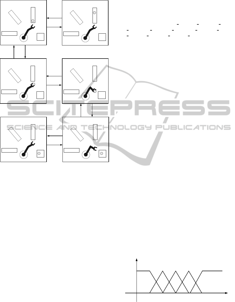
Running Example
According to figure 3:
• A set of positions {p
1
, p
2
,...} : A position is used
to localise the workpiece A, B or AB;
• A set of robotic agents {r
1
, r
2
, ...} : Each robotic
agent transfers a workpiece one after one to be
processed;
• A set of workpieces of type A {a
1
,a
2
, ...};
• A set of workpieces of type B {b
1
,b
2
, ...};
• A set of workpieces of type AB {ab
1
,ab
2
, ...};
ENASE2015-10thInternationalConferenceonEvaluationofNovelSoftwareApproachestoSoftwareEngineering
272
A Position
p1
Position
p2
Robot r
Processing
unit M
S
0
C1_right
C1_left
take1 put1
A
Conveyor
C1
C
o
n
v
e
y
o
r
C
3
Conveyor
C2
Position
p1
Position
p2
Robot r
Processing
unit M
S
1
A
Position
p1
Position
p2
Robot r
Processing
unit M
S
3
Position
p1
Position
p2
Robot r
Processing
unit M
A
S
4
Conveyor
C1
C
o
n
v
e
y
o
r
C
3
Conveyor
C2
Conveyor
C2
Conveyor
C2
Conveyor
C1
Conveyor
C1
C
o
n
v
e
y
o
r
C
3
C
o
n
v
e
y
o
r
C
3
A
Conveyor
C1
C
o
n
v
e
y
o
r
C
3
Conveyor
C2
Position
p1
Position
p2
Robot r
Processing
unit M
S
2
R1_left
R1_right
take1put1
Conveyor
C1
C
o
n
v
e
y
o
r
C
3
Conveyor
C2
Position
p1
Position
p2
Robot r
Processing
unit M
A
S
5
R1_right
R1_left
Figure 3: The first state-transition for RARM.
• A set of conveyors {C
1i
, C
2i
, C
3i
} : A conveyor C
1i
(resp. C
2i
, C
3i
) is responsible for transfering set of
workpieces of type A (resp B, AB);
• A set of processing Centers M {M
1
, M
2
,...} : first
one A-workpiece is inserted into M and processed,
then one B-workpiece is added into the center M,
and last both workpieces are assembled.
The set of states is {s
0
, s
1
, s
2
, s
3
, s
4
, s
5
, s
6
, s
7
, s
8
, s
9
,
s
10
, s
11
, s
12
, s
13
, s
14
, s
15
, s
16
}
There are nine possible actions in the domain.
• a workpiece of type A is trasnported to the left
from position p1 to position p2;
• the robotic agent transports a workpiece of type
A;
• the piece is put in the processing unit M;
• a workpiece of type B is trasnported to the left
from position p3 to position p4;
• the robotic agent transports a workpiece of type
B;
• the piece is put in the processing unit M;
• the robotic agent picks up the assembled piece;
• the assembled piece is put on the conveyor C3;
• a workpiece of type AB is trasnported to the right
from position p5 to position p6.
The set of actions is {C1
le ft, C1 right, R1 left,
R1
right, C2 left, C2 right, R2 le ft, R2 right,
C3 left, C3 right, R3 left, R3 right, take
1
, take
2
,
take
3
, load
1
, load
2
, load
3
, put
1
, put
2
, put
3
, process
1
,
process
2
}
6 COMPETENCE MODEL
The Competence Model of a robotic agent is based on
a Fuzzy Logic Control. This methodology is usually
applied in the only cases when exactitude is not of
the need or high importance (Jianhua Dai, 2013). The
basic form of a fuzzy logic agent consists of (Zadeh,
2008): Input fuzzification, Fuzzy rule base, Inference
engine and Output defuzzification.
Running Example
(i) Fuzzification. The number of defected pieces is
measured through a sensor related to the system. The
range of number of defected pieces varies between 0
to 40, where zero indicates the rate of defected pieces
of A that is null (each piece is well) and 40 indicates
the rate of defected pieces of A is very high.
Now assume that the following domain meta-data val-
ues for these variable, VF = very few, F = few, Md
= medium, Mc = much, VMc = very much. Assume
that the linguistic terms describing the meta-data for
the attributes of entities are: VF = [0,..,10], F =
[5,..,15], Md = [10,..,20], Mc = [15,..,25] and VMc
= [20,..,40].
Based on the metadata value for each attribute the
membership of that attribute to each data classifica-
tion can be calculated. In the Figure 4, triangular and
trapezoidal fuzzy set was used to represent the state
of defected pieces from A classifications (i.e. state of
defected pieces from A classification levels: VF , F,
Md, Mc, VMc whereas state of defected pieces from B
classification levels: F, Md, Mc).
Number of
defected pieces A
VF Md VMc
1
0
Degree of
Membership
F Mc
5 10 252015
Figure 4: Fuzzy State of defected pieces from A.
BuildingMulti-RobotSystembasedonFiveCapabilitiesModel
273
(ii) Rule Engine
We take as example, the first column from the Table 1
:
IF number of defected pieces from A is Very Few and
number of defected pieces from B is Few Then Pro-
duction is High.
IF number of defected pieces from A is Few and num-
ber of defected pieces from B is Few Then Production
is High.
...
Table 1: Fuzzy Control rules for the robotic agent.
A B F Md Mc
VF H H M
F H H M
Md H M L
Mc M L N
VMc M L N
(iii) Defuzzification. Defuzzification is the conver-
sion of a fuzzy quantity to a precise quantity. There
are many methods to calculate it such as Max mem-
bership, Centroid method, Weighted average method,
Mean max membership, Center of sums, Center of
largest area and First (or last) of maxima. Obviously,
the best defuzzification method is context-dependant
(Zadeh, 2008).
7 COMMUNICATION MODEL
Communication is responsible for communicative in-
teractions within a multi-robot system. Message ex-
change enables robotic agents to share information
directly and set up collaborations. The communica-
tion module processes incoming messages and pro-
duces outgoing messages according to well-defined
communication protocols. To do that, we implement
the different robotic agents with the platform JADE
(for more details, we refer to (Fabio Bellifemine,
2010b), (Caire, 2009), (Fabio Bellifemine, 2010a),
(Fabio Bellifemine, 2004)).
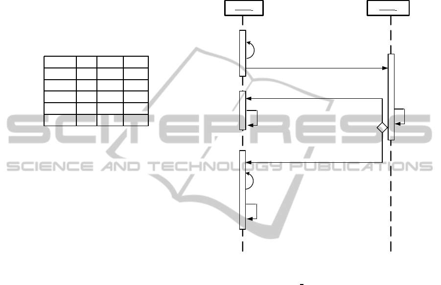
Running Example
In the Communication Model, we distinguish two
kinds of participating:
• The Initiator robotic agent (RARM
a
): it is the
robotic agent which starts the communication. In
fact, whenever an event occurs in a specific plant,
the associated robotic agent RARM
a
acts to man-
age it. If it decides to apply a new policy, then it
informs the other robotic agents. It searches the
list of robotic agents, sends a request to apply a
new policy and waits the response from them.
• The robotic Agent (RARM
b
): it is the i
th
agent
that receives a request from Initiator robotic agent
(RARM
a
) for a new policy. Firstly, it checks the
possibility to apply this new policy. If it is possi-
ble, it sends a positive answer. If it is not possible,
it sends a negative answer (see Figure 5).
RARM
a
RARM
b
Search the robotic
agents
*[j:=1..nbR, j <> i] Ask for new policy
* [nbResp = nbR- 1]
refuse
accept
apply the new policy
cancel the new policy
treat the
request
Figure 5: The scenario communication.
Algorithm: RARM
Communicate().
begin
if (requesting==true)
switch (step)
case 0:
RARMagent = searchAgent();
NbRobots = RARMagent.length();
// Send the request to all RARM Agents
for (int j = 1; j <= NbRobots; j++)
if (j ! = i)
msg.addReceiver(RARMagent[j]);
msg.setContent(policy);
msg.setPerformative(REQUEST);
msg.setTime(currentTime());
send(msg);
step++;
break;
case 1:
// Receive all accept/refusals from RARM Agents
reply = receive();
if (reply ! = null)
if (reply.getPerformative() == ACCEPT)
ENASE2015-10thInternationalConferenceonEvaluationofNovelSoftwareApproachestoSoftwareEngineering
274

nbResp++;
if (nbResp == NbRobots-1)
step++;
else
block();
break;
case 2:
// apply the new policy
setPolicy(p);
applyPolicy(p);
step = 0;
break;
end
8 CONCLUSION
The main aim of this paper is how to ensure a dis-
tributed planning in Multi-Robot System composed
of several intelligent autonomous robotic agents able
to take the initiative instead of simply reacting in
response to its environment. Our solution to this
problem is the use of the 5 Capabilities Model (as
it was presented, 5 levels: Environment, Self, Plan-
ner, Competence and Communication). The 5 Ca-
pabilities Model can be easily implemented where
each model is represented with a process collaborat-
ing with the other processes. The 5C Model, based
on the principle of separation of concerns, has the
following interests: (i) The design is general enough
to cope with various kinds of embedded-software ap-
plication (therefore, the 5C Model is uncoupled from
the application); (ii) The robotic agent is represented
through five dimensions where each model is inde-
pendent from the other which permits to change one
without having to change the other.
Our future work is the design of an autonomous
robot integrating cognitive abilities with other capa-
bilities such as locomotion, prehension, and manipu-
lation where each of these robot capabilities involves
different aspects of intelligence, and different intelli-
gent tools have to be used consistently to implement
them.
REFERENCES
Bordini, R. and all. (2006). A survey of programming lan-
guages and platforms for multi-agent systems. Infor-
matica, 30(1):33–44.
Branislav Hrz, M. Z. (2007). Modeling and control of
discrete-event dynamic systems with petri nets and
other tools. page 67.
C. J. van Aart, B. J. W. and Schreiber, A. T. (2004). Or-
ganizational building blocks for design of distributed
intelligent system. International Journal of Human-
Computer Studies, 61(5):567599.
Caire, G. (2009). JADE TUTORIAL : JADE PROGRAM-
MING FOR BEGINNERS.
Chuan-Jun Su, C.-Y. W. (2011). Jade implemented mo-
bile multi-agent based, distributed information plat-
form for pervasive health care monitoring. Applied
Soft Computing, 11(1):315–325.
David Jung, A. Z. (1999). An architecture for dis-
tributed cooperative planning in a behaviour-based
multi-robot system. Robotics and Autonomous Sys-
tems, 26(23):149–174.
Fabio Bellifemine, Giovanni Caire, D. G. (2004). Develop-
ing Multi-Agent Systems with JADE.
Fabio Bellifemine, Giovanni Caire, T. T. G. R. (2010a).
JADE PROGRAMMERS GUIDE.
Fabio Bellifemine, Giovanni Caire, T. T. G. R. R. M.
(2010b). JADE ADMINISTRATORS GUIDE. The
publishing company.
Jianhua Dai, H. T. (2013). Fuzzy rough set model for set-
valued data. Fuzzy Sets and Systems, 229(3):54–68.
Malik Ghallab, Dana Nau, P. T. (2004). Automated Plan-
ning.
Malik Ghallab, Dana Nau, P. T. (2014). The actor’s view
of automated planning and acting: A position paper.
Artificial Intelligence, 208(3):1–17.
Oscar Sapena, Eva Onaindia, A. G. M. A. (2008). Engi-
neering applications of artificial intelligence. Some
Fine Journal, 21(5):698–709.
Pascal Forget, Sophie DAmours, J.-M. F. (2008). Multi-
behavior agent model for planning in supply chains:
An application to the lumber industry. Robotics and
Computer-Integrated Manufacturing, 24(5):664–679.
Salvatore Vitabile, Vincenzo Conti, C. M. F. S. (2009). An
extended jade-s based framework for developing se-
cure multi-agent systems. Computer Standards & In-
terfaces, 31(5):913–930.
Sergio Pajares Ferrando, E. O. (2013). Context-aware
multi-agent planning in intelligent environments. In-
formation Sciences, 227:22–42.
van Aart, C. J. (2004). Organization principles for multi-
agent architectures. PhD thesis, University of Amster-
dam, Faculty of Social and Behavioural Sciences.
Zadeh, L. A. (2008). Is there a need for fuzzy logic? Infor-
mation Sciences, 178(13):2751–2779.
BuildingMulti-RobotSystembasedonFiveCapabilitiesModel
275
