
The Algorithm for Getting a UML Class Diagram from Topological
Functioning Model
Arturs Solomencevs and Janis Osis
Department of Applied Computer Science, Riga Technical University, Riga, Latvia
Keywords: Topological Functioning Model, Formal Problem Domain Model, Model Driven Architecture, Algorithm
for Automatic Model Transformation, UML Class Diagram.
Abstract: The approach called Topological Functioning Modeling for Model Driven Architecture (TFM4MDA) uses
Topological Functioning Model (TFM) as a formal problem domain model. TFM is used as a computation
independent model (CIM) within Model Driven Architecture (MDA). Following the recommendations of
MDA a CIM must be transformed to a platform independent model (PIM). The object of this research is the
construction of a UML class diagram on PIM level in conformity with the TFM. Nowadays this
transformation is executed manually. Manual creation of models is time-consuming; also a probability
exists, that a user (e.g., system architect) will make a mistake during the execution. Time investment and
risk of making mistakes increase costs and reduce efficiency of TFM4MDA approach. That is why
automation of this process is useful. The paper presents an algorithm for the transformation. The algorithm
is written in pseudocode and can be implemented as a tool, thus improving the TFM4MDA approach.
1 INTRODUCTION
Model Driven Architecture (MDA) is an approach to
system development, which increases the power of
models in this work. The purpose of MDA is to
separate the views and concerns. MDA has three
viewpoint and their corresponding models: a
computation independent model (CIM) contains
knowledge about the problem domain and the
requirements for software system; platform
independent model (PIM) focuses on the operation
of a system while hiding the details necessary for a
particular platform; and platform specific model
(PSM) (Miller and Mukerji, 2003). Model
transformation forms a key part of MDA. To get the
software source code we need to go by the path CIM
→ PIM → PSM → source code.
Topological functioning model (TFM) is a
formal model which describes the functioning of
system. The TFM has a solid mathematical base.
The model-driven software development approach
called Topological Functioning Modeling for Model
Driven Architecture (TFM4MDA) is based on TFM
(Osis et al., 2007a). TFM4MDA introduces more
formal analysis and modeling of the problem domain
within MDA (Osis et al., 2007b), (Osis and Asnina,
2011b). TFM within MDA is used as a CIM.
Since TFM is a formal model, its usage has the
following benefits:
Possibility of transformation to PIM (within
MDA);
Guarantee, that software product completely
satisfies functional requirements;
Design process and code generation can be at
least partially automated;
The correctness of operation of the entire system
is mathematically proven.
The object of this research is transformation from
the TFM to a UML class diagram (OMG UML,
2011) on PIM level. UML class diagram is
important in software development, because it
displays the structure of the software system and
indicates class responsibilities. Nowadays the
creation of a class diagram from the TFM requires
fully manual execution. Manual execution is time-
consuming; also a probability exists, that a user
(e.g., system architect) will make a mistake during
the execution. Time investment and risk of making
mistakes increase the costs of software development.
The costs must be minimized. Therefore the goal of
the research is to automate the transformation from
the TFM to a UML class diagram. The algorithm of
automated transformation is developed. There is a
341
Solomencevs A. and Osis J..
The Algorithm for Getting a UML Class Diagram from Topological Functioning Model.
DOI: 10.5220/0005474303410351
In Proceedings of the 10th International Conference on Evaluation of Novel Approaches to Software Engineering (MDI4SE-2015), pages 341-351
ISBN: 978-989-758-100-7
Copyright
c
2015 SCITEPRESS (Science and Technology Publications, Lda.)

possibility to develop a tool which will execute the
transformation algorithm. As a result of
transformation the initial UML class diagram (with
attributes, operations, and without relationships
among classes) on PIM level is constructed.
The paper is structured as follows. Section 2
describes related work – other software development
approaches (apart from TFM4MDA) that include the
creation of CIM are overviewed. In Section 3 TFM,
MDA and TFM4MDA are described in more detail.
In Section 4 the creation of class diagram from TFM
is described. In Section 5 the transformation
algorithm from TFM to UML class diagram is
introduced. In Section 6 conclusions are presented.
2 RELATED WORK
There are different approaches for domain modeling
that include the creation of CIM. Since model
transformation is a key part of MDA, we are
interested in approaches that give an opportunity to
create a class diagram on PIM level from the CIM.
Business Process Modeling and Notation
(BPMN) is an OMG standard (OMG BPMN, 2013).
BPMN is used for modeling the problem domain
within the Business Process Modeling approach.
BPMN model is positioned on CIM level within
MDA (Linagora). BPMN can be transformed to a
UML activity diagram on CIM level, and the activity
diagram can be transformed to a class diagram on
PIM level. However, author of paper (Bao, 2010)
made a conclusion that the gap between BPMN and
UML is too large so the creation of an activity
diagram from BPMN model is limited under some
situations. Not all BPMN elements can be
transformed without the loss of information or
meaning.
ArchiMate is an Open Group Standard which
provides a graphical language for the representation
of enterprise architectures (The Open Group, 2013).
A CIM is created at ArchiMate business layer. A
Meta Object Facility meta-model (OMG MOF,
2014) for the ArchiMate language does not exist
today (Armstrong, 2013). It means that the formal
transformation from an ArchiMate CIM to a UML
class diagram on PIM level does not exist.
A development approach that is supported by a
tool named Use-Case driven Development Assistant
(UCDA) allows to convert the functional
requirements into a class model semi-automatically.
The functional requirements are specified and
represented by use cases (Liu, 2003), (Liu et al.,
2004). So the use case model is used as a CIM.
Using a use case model as a CIM is disputable,
because it is fragmentary. There is no way to tell
whether the model is complete. Furthermore, it can
be hard to check whether there are no conflicts (the
bigger the model – the harder to check). So a use
case model is not applicable as a CIM for modeling
big systems. This drawback is shared by other
software development approaches that are driven by
use case modeling. Comparing to TFM, a use case
model lacks formalism. The disadvantage of using a
use case model is discussed in more detail in Section
3.
A methodology and a tool, Linguistic assistant
for Domain Analysis (LIDA), provide linguistic
assistance in the model development process. The
goal of this method is to utilize existing text
descriptions of a problem domain, and from them,
produce an initial conceptual class diagram with
attributes, methods and roles (Overmyer et al.,
2001). The conceptual class diagram is a PIM level
model. Prior to using the methodology, the analyst
should already have prepared a set of use cases or
scenarios that represent the operational concept for
the proposed system (Overmyer et al., 2001). So
LIDA helps with analyzing texts (e.g., documents,
descriptions of problem domain), but the analyst has
to identify which classes are relevant based on prior
developed use case model. Hence use cases take
place as a CIM within LIDA approach. Therefore
LIDA approach is driven by use case modeling, and
has the same drawback that we discussed in the
previous paragraph.
Semantics of Business Vocabulary and Business
Rules (SBVR) is another OMG specification that
defines the vocabulary and rules for documenting
the semantics of business vocabularies and business
rules for the exchange among organizations and
between software tools (OMG SBVR, 2013). In
paper (Raj et al., 2008) the authors introduce an
approach to transform the SVBR model to a UML
class diagram on PIM level. The process has
limitations. Authors are not able to find out the input
parameters of class’s methods. For this moment this
drawback also appears within TFM4MDA approach
(in transformation to a class diagram). As far as the
authors of this work understand, SBVR model is
fragmentary. Hence it has the same drawbacks as the
use case model.
In Natural Language Based Requirements
Analysis (NIBA) the textual requirements
specifications are firstly linguistically analyzed and
translated into a so-called conceptual predesign
schema - Klagenfurt Conceptual Predesign model
(KCPM) (Fliedl et al., 2007). KCPM provides a user
ENASE2015-10thInternationalConferenceonEvaluationofNovelSoftwareApproachestoSoftwareEngineering
342

(stake-holder) centered form or requirement
documentation, which means that the model can be
understood and validated by the users (Mayr and
Kop, 2002). KCPM can be considered as a CIM,
because it has the characteristics of CIM. KCPM can
be mapped to a UML class diagram (Mayr and Kop,
2002). A drawback of NIBA approach is that the
requirements must be written in German language so
that they could be automatically analyzed and
translated to a KCPM. The authors of this paper
conclude that KCPM is not formal – in papers (Mayr
and Kop, 2002) and (Fliedl et al., 2007) nothing is
told about formalism. Also the mapping to a class
diagram is not strict. The mapping rules are divided
into laws and proposals; the designer may accept the
proposal or take another decision (Mayr and Kop,
2002). Hence there is no formal transformation to a
class diagram.
In the overviewed approaches CIM is created
informally. Hence these approaches do not share
benefits of formal domain modeling (mentioned in
Section 1). Since the CIM is informal, it is hard to
define a formal transformation from the CIM to a
PIM – an unambiguous transformation that can be
automated. TFM in its turn is a formal CIM and the
formal transformation to PIM is defined.
3 TOPOLOGICAL
FUNCTIONING MODEL
WITHIN MDA
Nowadays object oriented approach is most widely
used in software development. In object oriented
approaches, for example, Rational Unified Process
(RUP), the problem domain functioning descriptions
usually are ignored, and development starts with the
analysis of the application domain descriptions
(commonly, use cases). This tendency is disputable,
because use case diagram is fragmentary. There is
no way to determine whether a created use case
diagram is complete or something is missed. This
also refers to the list of requirements for the software
system. Furthermore, only proper problem domain
model provides a powerful language for expressing
requirements for the system (Osis and Asnina,
2011a). Explicit problem domain model gives an
opportunity to understand how the system (e.g.,
business system) is working without software which
is planned to be developed, and how this system will
be influenced by the software. This way it is
possible to understand not only what the client
wants, but also what they need – so records are
added to the list of requirements. If the client’s
needs and desires are clearly determined, the
probability of their satisfaction with software
product essentially increases. A proper model is a
formal model. Hence the formalism must be
involved in the very early stage of software
development (Osis and Asnina, 2011a).
Model Driven Approach is an approach to
system development, which increases the power of
models in that work. It is model-driven because it
provides a means for using models to direct the
course of understanding, design, construction,
deployment, operation, maintenance and
modification (Miller and Mukerji, 2003). Model
transformation forms a key part of MDA.
CIM is a computation independent model, PIM is
a platform independent model, and PSM is a
platform specific model. With the help of model
transformations, going by the path CIM → PIM →
PSM → software code, from an abstract model
(CIM) a detailed model (PSM) is obtained. It is
possible to generate software source code from
PSM.
The requirements for the system are modeled in a
computation independent model, CIM describing the
situation in which the system will be used. Such a
model is called a domain model or a business model
(Asnina and Osis, 2011). It may hide much or all
information about the use of automated data
processing systems. Typically such a model is
independent of how the system is implemented. A
CIM is a model of a system that shows the system in
the environment in which it will operate, and thus it
helps in presenting exactly what the system is
expected to do. Topological functioning model has
the above mentioned characteristics of CIM.
Topological functioning model is a formal model
which describes the functioning of system. The TFM
has a solid mathematical base. It is represented in a
form of a topological space (X, Θ), where X is a
finite set of functional features of the system under
consideration, and Θ is topology that satisfies
axioms of topological structures and is represented
in a form of a directed graph (Osis, 1969). The
TFM’s functional features describe the system’s
physical or biological characteristics that are
relevant for the normal functioning of the system.
The TFM’s topology consists of cause-effect
relations between functional features. Cause-effect
relation exists between two functional features, if
appearance of one functional feature is caused by
appearance of the other without participation of any
middle functional feature (Osis, 1969). Cause-effect
relations form causal chains. Causal chains must
TheAlgorithmforGettingaUMLClassDiagramfromTopologicalFunctioningModel
343
form at least one functioning cycle within TFM. All
the cycles and subcycles should be carefully
analyzed in order to completely identify existing
functionality of the system. The main cycle (cycles)
of system functioning (i.e. functionality that is
vitally necessary for system’s life) must be found
and analyzed before starting further analysis. TFM
has topological (connectedness, closure,
neighborhood, and continuous mapping) and
functional (cause-effect relations, cycle structure,
inputs and outputs) characteristics. Due to
topological and functional characteristics mentioned
above TFM comprises two aspects of the system –
both structural and behavioral (Osis and Asnina,
2011b).
It is proposed to use TFM as a formal CIM in the
framework of MDA to model the problem domain
(Osis and Asnina, 2011 b). In the paper (Osis et al.,
2007 a) this approach is called Topological
Functioning Modeling for Model Driven
Architecture. TFM4MDA is a model-driven
approach which is based on the formalism of TFM.
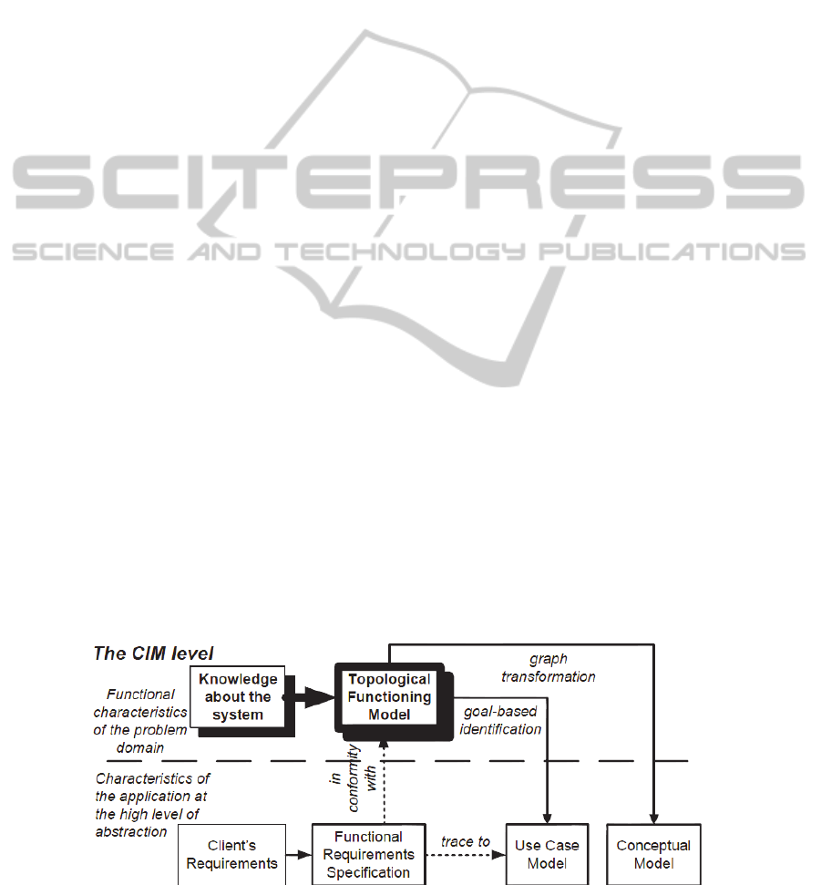
Figure 1 illustrates the place of CIM (which is a
TFM) in the approach.
There are two stages of the problem analysis:
analysis of the problem domain and analysis of the
application (solution) domain. These levels should
be analyzed separately. TFM considers problem
domain information separate from the application
domain information captured in requirements and
thus satisfies the main principle of MDA –
separation of views (Asnina and Osis, 2010) The
horizontal dashed line in Figure 1 separates the
problem domain (above) from the application
domain (below). The knowledge about the problem
domain is entered into TFM and a TFM “as is” is
developed (Osis and Asnina, 2011c). The
requirements are mapped onto the TFM’s functional
features, so the requirements are validated and the
TFM is modified. In this way a TFM “to be” is
developed – a model of problem domain which will
be supported by required software (Osis and Asnina,
2008). It is possible to create a use case model (Osis
and Asnina, 2011d) and a conceptual class model
from a TFM. Mapping requirements onto functional
features and creation of use case model and
conceptual class model are described in detail in
(Osis et al., 2007c), (Osis and Asnina, 2011b).
TFM of a complex technical or business system
can be constructed from its informal verbal
description – the formal method is described in
detail in (Osis and Asnina, 2011b), which is based
on (Booch, 1994). Another approach for TFM
creation is the Integrated Domain Modeling
approach (IDM). By using IDM approach
knowledge about a problem domain is represented
by ontology and business use cases (Slihte et al.,
2011). Ontology represents the declarative
knowledge (structure), and business use cases
represent the procedural knowledge (behavior) about
the system. Business use cases must be in
conformity with ontology – verification takes place,
and the models are modified until the conformity is
achieved. Then the TFM can be created from
business use cases. The construction of TFM from
business use cases can be done automatically by
using the tool (Slihte et al., 2011).
4 CREATING A CLASS
DIAGRAM FROM THE TFM
The goal of software development is to get the
software source code. As it was mentioned before, to
get the source code (within MDA) we need to go by
the path CIM → PIM → PSM → source code. So in
the beginning PIM must be created from CIM. UML
class diagram (Rumbaugh et al., 2004) can serve as
PIM which represents the structure of a system.
Figure 1: CIM creation with the TFM4MDA (taken from (Osis et al., 2007a)).
ENASE2015-10thInternationalConferenceonEvaluationofNovelSoftwareApproachestoSoftwareEngineering
344

Class diagram can be detailed to PSM level,
although it is a task of the future research. In this
paper we focus on construction of UML the class
diagram on PIM level from TFM (TFM is CIM).
The approach of construction of topological
UML class diagram from TFM is described in (Osis
and Donins, 2010a). Topological class diagram has
topological relationships (see section 4.2). There is
no algorithm for automatic transformation from
TFM to topological class diagram.
As it was mentioned before, TFM consists of the
set of functional features and cause-effect relations
between functional features.
4.1 TFM Functional Features
Within the TFM4MDA each functional feature is a
5-tuple <A, R, O, PrCond, E>, where A is an object
action, R is a result of this action, O is an object
(objects) that receives the result or that is used in
this action (for example, a role, a time period, a
catalog, etc.), PrCond is a set PrCond = {c
1
, …, c
i
},
where c
i
is a precondition or an atomic business rule
(it is an optional parameter), and E is an entity
responsible for performing actions (Osis and Asnina,
2011 b). In paper (Osis and Donins, 2010 a)
attributes are added, forming the 8-tuple: <A, R, O,
PrCond, PostCond, E, Cl, Op>, where PostCond is a
set PostCond = {p1, …, pi}, where pi is a
postcondition or an atomic business rule; Cl – Class
- is a class which will represent the object in system
static (structure) model and which will contain
operation for functionality defined by this functional
feature; Op – Operation – is an operation which will
contain functionality defined by functional feature.
The main idea is that the functionality of each
functional feature must be realized by individual
class method. So Cl and Op attributes are needed to
construct a class diagram from TFM: Cl is name of a
class, and Op is name of a method. Cl and Op
attributes are initialized (values are assigned) only
when a class diagram is needed to be constructed.
Other 8-tuple attributes (apart from Cl and Op) are
not displayed in class diagram, however, they help
to initialize Cl and Op attributes.
4.2 TFM Topology
UML specification (OMG UML, 2011) does not
propose a type of relation between classes that can
be compared with topological (cause-effect) relation
(Osis and Donins, 2010a). For this reason in paper
(Osis and Donins, 2010a) topological relation
between classes is introduced. However, this
solution requires the extension of meta-model of
class diagram with the goal to create the meta-model
of topological class diagram, which has the
description of topological relations (Osis and
Donins, 2010b). Modifying the meta-model is bad
because of the following reasons: many software
tools are constructed based on the standard UML
meta-model and are not able to work with other
meta-models (Rumbaugh et al., 2004); there is a
possibility that user (e.g., system architect) would
not like to work with the class diagram which differs
from the standard one. For these reasons we focus
on the transformation from TFM to the standard
UML class diagram. Since TFM’s cause-effect
relations cannot be transformed to any UML
standard relation between classes, authors suggest
that the class diagram, which is a result of
transformation from TFM, has no relations.
Relations are added during the refinement of the
obtained class diagram (Donins et al., 2011).
4.3 The Process of Creating a Class
Diagram from the TFM
To execute the transformation from TFM to UML
class diagram TFM, the attributes Cl and Op of
functional features must be initialized (not necessary
all of them). It is a user’s (e.g., system architect’s)
responsibility.
In order to obtain a class diagram, first of all a
graph of problem domain objects must be developed
from TFM. It is a simple transformation, where all
unnecessary attributes of TFM’s functional features
are cut – only Cl and Op are remained. Then the
graph vertices with similar Cl values are merged and
a new class is created – with name Cl and the class’s
list of methods consists of Op values of these
vertices (Osis and Donins, 2010 a). Figure 2 shows
the process of creating the class diagram from TFM.
4.4 Introducing the Automation
Authors propose to automate the process’s part
which starts after assigning values to Cl and Op
attributes (this is done manually). In papers (Osis
and Donins, 2010a) and (Donins, 2010) there are no
guidelines and the way of creating Cl and Op values
is not clear. So the development of guidelines for
initializing Cl and Op requires the future research.
The transformation ends with creation of the class
diagram.
Since the graph of domain objects with
operations serves as a linking model, authors
propose not to display this model, but only to create
TheAlgorithmforGettingaUMLClassDiagramfromTopologicalFunctioningModel
345
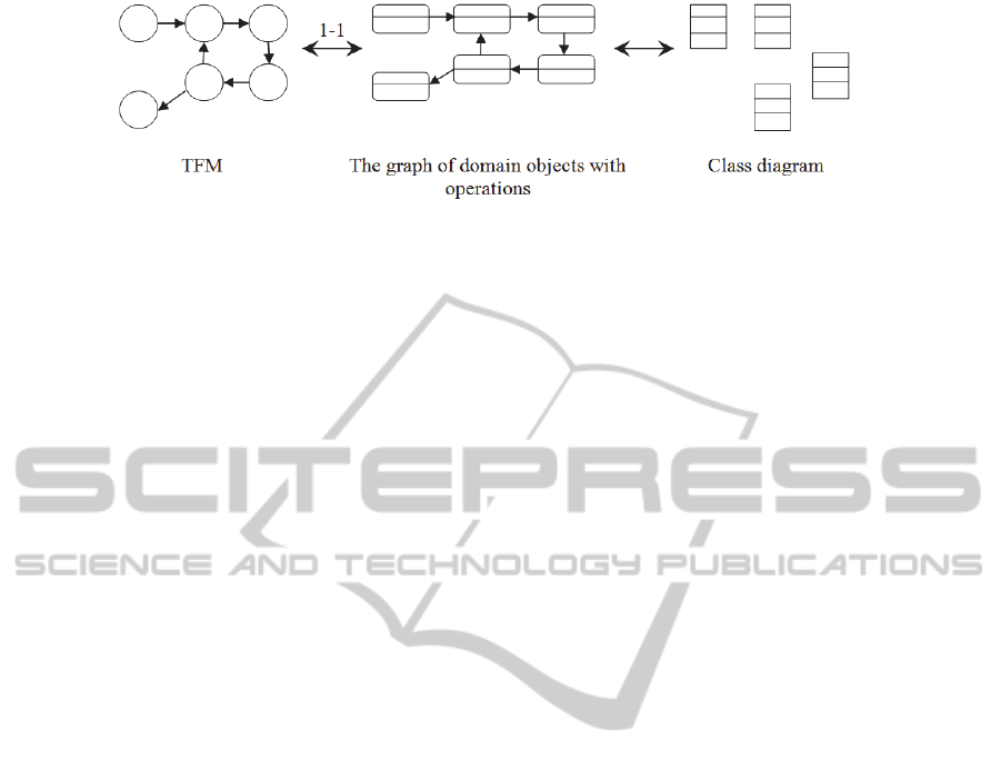
Figure 2: The process of creating a class diagram from the TFM.
it in memory during execution of the transformation
program. As a result of the automated
transformation, the initial class diagram on PIM
level is created. This diagram consists of classes
with names and lists of methods. The refinement of
the initial class diagram is done manually (Donins et
al., 2011).
The automation of model transformation lightens
user’s (e.g., analyst, system architect). Therefore the
cost of software development is decreased. This way
the system analysis stage (TFM development) is
connected to the development of UML model on
PIM level.
5 THE ALGORITHM OF THE
AUTOMATIC
TRANSFORMATION FROM
TFM TO UML CLASS
DIAGRAM
5.1 Developing a Graph of Problem
Domain Objects from the TFM
Firstly the graph of problem domain objects with
operations must be developed from TFM. For each
TFM’s functional feature a vertex in the graph must
be created and its attributes must be initialized with
the corresponding functional feature’s attributes.
Figure 3 shows an example of developing the graph
of problem domain objects from TFM. Attribute ID
(identifier) is added for algorithm realization.
Attribute Description consists of the following
functional feature’s attributes: action (A); result (R);
object (O) (section 3.1).
The algorithm for developing the graph of
problem domain objects from the TFM in
pseudocode:
// The vertex of the problem domain
// object graph is described by the
// following code:
struct DomainObjectVertex
{
id : Integer; // primary key
class : String;
operation : String;
// The set of integer numbers which
// includes identifiers of vertices
// which are connected to the given
// vertex with an oriented edge.
// The edge is oriented from the
// given (this) vertex to the vertex,
// which identifier is included in
// the set.
edges : Set of Integer;
};
// The TFM’s functional feature is
described by the following code:
struct FunctionalFeature
{
id : Integer; // primary key
description : String;
entity : String;
class : String; // Cl attribute
operation : String; // Op attribute
};
// Topological (cause-effect)
// relationship is described by the
// following code:
struct TopologicalRelationship
{
// id of “cause” functional feature:
source : Integer;
// id of “effect” functional feature:
target : Integer;
};
T: is a set of TFM’s functional
features; t[i] is a functional
feature with id = i;
G: is a set of vertexes of the problem
domain object graph; g[i] is a vertex
with id = i;
R: is a set of topological
relationships;
At the beginning:
{
G = Ø (empty set);
T includes all TFM’s functional
features;
ENASE2015-10thInternationalConferenceonEvaluationofNovelSoftwareApproachestoSoftwareEngineering
346
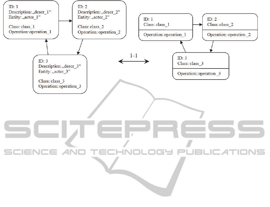
Figure 3: An example of developing a graph of problem domain objects from the TFM.
R includes all topological
relationships from TFM.
}
// The problem domain object graph is
// developed iteratively. During
// iteration a vertex is created and
// added into the set G.
// T.size() – number of functional
// features in the set T.
For i:=1 to T.size() do
{
// create new vertex of object graph:
create DomainObjectVerticy type
variable v;
v.id := i;
v.class := t[i].class;
v.operation := t[i].operation;
// the set of edges will be created
// later, for now it is an empty set:
v.edges := Ø;
// add vertex v into the set G:
G := G ⋃ {v};
}
r – TopologicalRelationship type
instance; // declaration of variable r
// Transferring of TFM relationships
// into the object graph. Process runs
// iteratively.
// During iteration r becomes an
// element of the set R.
// r.source is a “cause” functional
// feature’s id and also the
// corresponding vertex’s id.
// Hence g[r.source] is graph’s vertex
// from which the edge comes out.
// r.target is the object graph’s
// vertex into which incomes the edge
// under consideration.
// Hence r.target value must be added
// into the g[r.source].edges set.
For all r ∈ R do
g[r.source].edges :=
g[r.source].edges ⋃ {r.target};
5.2 Creating a Class Diagram from the
Graph of Problem Domain Objects
The attributes class and operation of vertices in the
developed graph of problem domain objects are
equal to the attributes Cl and Op of TFM’s
functional features that correspond to these vertices.
If Cl or Op attribute of a functional feature is empty,
then the corresponding attribute of the
corresponding vertex in the graph is also is empty.
For this reason user (e.g., system architect) has an
opportunity to check the class diagram before
assigning values to all Cl and Op attributes in TFM.
Hence the algorithm must support the creation of the
class diagram from the TFM in which not all Cl and
Op attributes are initialized (the value is assigned).
Four cases are possible:
1) Both Cl and Op attributes of a functional feature
are initialized. In this case the corresponding
vertex of the graph participates in construction of
the class diagram – both class name and
operation name are taken into account.
2) Cl attribute is initialized, but Op – is not. In this
case the vertex does not add a new operation, but
the class with the name equal to value of class
attribute is added to the class diagram.
3) Op attribute is initialized, but Cl – is not. In this
case the vertex cannot participate in construction
of the class diagram, and the value of its
operation attribute is lost (it stays in TFM, but it
is not transferred to the class diagram).
4) Neither Cl nor Op attribute is initialized. In this
case the vertex is treated in a similar way to the
TheAlgorithmforGettingaUMLClassDiagramfromTopologicalFunctioningModel
347

third case.
It is possible to create the class diagram from the
constructed graph of problem domain objects. The
vertices of the graph with the same type of objects
(class values) must be merged (Osis et al., 2008).
Since it is not possible to transform the relationships
between TFM’s functional features to the class
diagram (section 3.2), the edges of the graph are
lost.
Class attributes (in the class diagram) are
generated from getter and setter methods (which
names start with get or set). Corresponding method
is retained in the list of methods of the class despite
the fact that the existence of an attribute implicitly
indicates that corresponding setter and getter exist.
The method needs to be there so that user (e.g.,
system architect) could see that the attribute was
generated from a method that was transformed from
TFM.
The algorithm of creating UML class diagram
from the graph of problem domain objects in
pseudocode:
// The class of UML class diagram is
// described by the following code:
struct Class
{
className : String;
// list of attributes:
attributes : List of String;
// list of methods:
operations : List of String;
};
G: is a set of vertexes of the problem
domain object graph; g[i] is a vertex
with id = i;
C: is a set of UML classes;
c is an element of the set C
(a class);
At the beginning:
{
C = Ø (empty set);
the set G was developed;
}
// The set C is developed iteratively.
// During iteration one element of the
// set G (one vertex) is inspected.
// The information that includes the
// vertex is used to develop the set C.
// G.size() – the number of vertices in
// the set G.
For i:=1 to G.size() do
{
// Firstly, the attribute class is
// checked. If it is empty, then the
// vertex does not improve the set C.
IF g[i].class is not empty, THEN
{
// Then the set C is checked
// whether it has an element with
// a class name equal to vertex’s
// g[i] class attribute. If it
// does not have, then a new class
// is added into the set C.
IF C does not have a class with
className that is equal to
g[i].class, THEN
{
// create a new class:
create Class type variable cNew;
cNew.className := g[i].class;
// for now lists of attributes
// and methods are empty:
cNew.attributes := Ø;
cNew.operations := Ø;
// add the class cNew into set C:
C := C ⋃ {cNew};
}
Designation: cCurrent – the C set’s
class which attribute className
is equal to g[i].class;
// The operation attribute of
// vertex g[i] is checked. If it is
// not empty, then
// cCurrent.operations list is
// checked whether it has an
// element that is equal to
// g[i].operation. If there is no
// such method in the list,
// then it is added.
IF g[i].operation is not empty,
THEN
IF g[i].operation is not in the
list cCurrent.operations,
THEN
cCurrent.operations :=
cCurrent.operations ⋃
{g[i].operation};
}
// Here ends the code block, which
// is executed if condition
// “IF g[i].class is not empty”
// is met.
}
// The “For i:=1 to G.size() do”
// loop ends here.
// declaration of variable c:
c – Class type instance;
// declaration of variable oper:
oper –String type instance;
// Generation of class’s attributes.
// The set C is processed iteratively.
// During iteration one class is
ENASE2015-10thInternationalConferenceonEvaluationofNovelSoftwareApproachestoSoftwareEngineering
348

// inspected.
For all c ∈ C
{
// Each method of a class is analyzed
// in turn.
For all oper ∈ c.operations do
{
IF oper begins with „set” or with
„Set”, or with „get”, or with
„Get”, THEN
{
create String type variable
newAttribute;
newAttribute := oper;
// To obtain the corresponding
// name of attribute the word
// „set” or „get” is cut.
crop the first 3 symbols of
newAttribute;
// Brackets are also cut.
IF last two symbols of
newAttribute are „()”, THEN
crop the last 2 symbols of
newAttribute;
// Attribute’s first letter
// should be written
// in lower case.
IF the first symbol of
newAttribute is written in upper
case, THEN
replace the first letter of
newAttribute with the
corresponding lower case
letter;
// Before adding newAttribute
// into the list of attributes we
// need to check if the list does
// not already have an attribute
// with the same name.
IF newAttribute is not in the
list c.attributes, THEN
c.attributes := c.attributes ⋃
{newAttribute};
}
}
// The „For all oper
∈
c.operations
// do” loop ends here.
}
// The „For all c
∈
C do” loop
// ends here
// After executing the above mentioned
// algorithm the set C is ready to be
// used for the class diagram
// construction. Classes are
// transferred to the UML class diagram
// space.
For all c ∈ C do
{
place a new class in the UML class
diagram and mark it as cDiagram;
assign cDiagram the class name
c.className;
add to the list of attributes of
cDiagram all attributes from the
list c.attributes;
add to the list of methods of
cDiagram all methods from the list
c.operations;
}
Figure 4 shows an example of a class diagram that is
constructed by executing (manually) the
transformation algorithm.
As a result of the transformation the initial UML
class diagram on PIM level is created (with
attributes and operations). To obtain the complete
class diagram on PIM level the initial class diagram
must be refined (Donins et al., 2011). The
refinement of class diagram is aimed to lower
abstraction level of it. By lowering abstraction level
the diagram gets additional information which is
needed during the software development and later
during its maintenance.
Figure 4: Example of a class diagram that is a result of execution of the transformation algorithm.
TheAlgorithmforGettingaUMLClassDiagramfromTopologicalFunctioningModel
349

6 CONCLUSIONS
This research focused on creation of a UML class
diagram from a Topological Functioning Model.
Authors worked on decreasing the costs of software
development within the TFM4MDA approach which
are related to creation of a UML class diagram on
PIM level from the TFM on CIM level. The
decrease can be achieved by automating the formal
transformation from the TFM to a class diagram.
The main accomplishment of this work is a
developed algorithm of transformation from the
TFM to an initial UML class diagram on PIM level.
The algorithm is written in pseudocode. It can be
implemented as a tool, thus improving the
TFM4MDA approach. So the link between the
beginning stage of system analysis (the development
of TFM) and the development of PIM becomes
stronger.
The next task is to implement the introduced
transformation algorithm as a tool. Thus TFM4MDA
approach will become more efficient. To practically
validate the result of the work, a tool (or tool
prototype) must be developed. Theoretically,
working with a tool that executes the transformation
is more effective than manually creating the initial
class diagram (classes with operations). First of all,
the larger the TFM is, the harder it becomes for
manual processing. The probability of making
mistakes grows. The automatic transformation
nullifies the risk of making mistakes during the
transformation. Secondly, the user must initialize Cl
and Op attributes only once for each functional
feature. During the development process TFM will
most likely be modified at least several times. After
a modification, the retained functional features will
still have the initialized Cl and Op attributes, which
will be used for the creation of a class diagram. This
approach is more effective than manually recreating
a class diagram, or trying to modify it accordingly to
the new version of TFM. Thirdly, working directly
with TFM in the TFM editor would be more
comfortable than working with TFM and UML class
diagram in two different editors during manual
transformation.
It is not yet known how the changes in the class
diagram should affect the TFM and whether they
should affect TFM. It would be better if the
modifications in TFM affected the class diagram. In
this case the user would not have to start from the
initial class diagram after modifying the TFM. For
now the developed transformation algorithm only
creates new initial class diagram that conforms to
TFM. The solutions for these problems should be
found in the future research.
REFERENCES
Armstrong, C., Baker, J.D., Band, I., Courtney, S.,
Jonkers, H., Muchandi, V., Owen, M. 2013, Using the
ArchiMate® Language with UML®, viewed 26
January 2014 <http://cdn2.hubspot.net/hub/183807/
file-1805596253-pdf/site/media/downloads/W134.pdf
?t=1418385713847>
Asnina, E., Osis, J. 2010, Computation Independent
Models: Bridging Problem and Solution Domains. In:
J. Osis, O. Nikiforova (Eds.). Model-Driven
Architecture and Modeling Theory-Driven
Development: ENASE 2010, 2ndMDA&MTDD Whs.,
SciTePress, Portugal, pp. 23 – 32.
Asnina, E., Osis, J. 2011, Topological Functioning Model
as a CIM-Business Model. In: Model-Driven Domain
Analysis and Software Development: Architectures
and Functions. IGI Global, Hershey - New York, pp.
40 – 64.
Bao, N. Q. 2010, A proposal for a method to translate
BPMN model into UML activity diagram, Vietnamese-
German University – BIS, viewed 24 January 2014,
<http://www.nqbao.com/archives/files/BPMN-
UMLAD.pdf>
Booch, G. 1994, Object-Oriented Design with
Applications. Addison Wesley Longman, Inc.
Donins, U. 2010, Software Development with the
Emphasis on Topology. In: Advances in Databases
and Information Systems: Lecture Notes in Computer
Science. Vol.5968. Berlin: Springer Berlin Heidelberg,
pp. 220-228. ISBN 9783642120817. E-ISBN
9783642120824. ISSN 0302-9743.
Donins, U., Osis, J., Slihte, A., Asnina, E., Gulbis. B.
2011, Towards the Refinement of Topological Class
Diagram as a Platform Independent Model. In: J.
Osis, O. Nikiforova (Eds.). Model-Driven Architecture
and Modeling-Driven Software Development: ENASE
2011, 3
rd
Whs. MDA&MDSD, SciTePress, Portugal,
pp. 79 - 88.
Fliedl, G., Kop, C., Mayr, H. C., Salbrechter, A.,
Vöhringer, J., Weber, G. Winkler, C. 2007, Deriving
static and dynamic concepts from software
requirements using sophisticated tagging, Data &
Knowledge Engineering, pp. 433-448.
Linagora. What is MDA? Why concerns BPMN? viewed
24 January 2014, <https://research.linagora.com/
pages/viewpage.action?pageId=3639295>
Liu D., Subramaniam, K., Eberlein, A., Far, B. H. 2004,
Natural Language Requirements Analysis and Class
Model Generation Using UCDA. In: Innovations in
Applied Artificial Intelligence: 17th International
Conference on Industrial and Engineering
Applications of Artificial Intelligence and Expert
Systems. Berlin: Springer, pp. 295 - 304.
Liu, D. 2003, Automating Transition from Use Cases to
Class Mode, Master Thesis. Calgary: University of
ENASE2015-10thInternationalConferenceonEvaluationofNovelSoftwareApproachestoSoftwareEngineering
350

Calgary.
Mayr, H. C., Kop, Ch. 2002, A user centered approach to
requirements modelling, in: Proc. Modellierung 2002,
Lecture Notes in Informatics LNI p-12, GI-Edition,
pp. 75–86.
Miller, J., Mukerji, J. 2003, MDA Guide Version 1.0.1,
OMG, viewed 24 January 2015,
<http://www.omg.org/cgi-bin/doc?omg/03-06-01>
OMG (Object Management Group) 2011, OMG Unified
Modeling LanguageTM (OMG UML), Superstructure,
Version 2.4.1, viewed 28 January 2015,
<http://www.omg.org/spec/UML/2.4.1/Superstructure/
PDF/>
OMG (Object Management Group) 2013, Business
Process Model and Notation (BPMN), Version 2.0.2,
viewed 24 January 2015, <www.omg.org/spec/
BPMN/2.0.2/PDF>
OMG (Object Management Group) 2013, Semantics of
Business Vocabulary and Business Rules (SBVR),
Version 1.2, viewed 24 January 2015,
<http://www.omg.org/spec/SBVR/1.2/PDF/>
OMG (Object Management Group) 2014, OMG Meta
Object Facility (MOF) Core Specification, Version
2.4.2, viewed 26 January 2015, <http://www.omg.org/
spec/MOF/2.4.2/PDF/>
Osis, J. 1969, Topological Model of System Functioning
(in Russian). Automatics and Computer Science, J. of
Academia of Siences, Riga, Latvia, Nr. 6, pp. 44-50.
Osis, J., Asnina, E. 2008, A Business Model to Make
Software Development Less Intuitive. Proceedings of
the 2008 International Conference on Innovation in
Software Engineering, Vienna, Austria. IEEE
Computer Society CPS, Los Alamitos, USA, 2008, pp.
1240 – 1246.
Osis, J., Asnina, E. 2011 a, Is Modeling a Treatment for
the Weakness of Software Engineering? In: Model-
Driven Domain Analysis and Software Development:
Architectures and Functions. IGI Global, Hershey -
New York, pp. 1-14.
Osis, J., Asnina, E. 2011 b, Topological Modeling for
Model-Driven Domain Analysis and Software
Development: Functions and Architectures. In: Model-
Driven Domain Analysis and Software Development:
Architectures and Functions. IGI Global, Hershey -
New York, pp. 15 – 39.
Osis, J., Asnina, E. 2011 c, Model-Driven Domain
Analysis and Software Development: Architectures
and Functions. IGI Global, Hershey - New York, 487
p.
Osis, J., Asnina, E. 2011 d, Derivation of Use Cases from
the Topological Computation Independent Business
Model. . In: Model-Driven Domain Analysis and
Software Development: Architectures and Functions.
IGI Global, Hershey - New York, pp. 65 – 89.
Osis, J., Asnina, E., Grave, A. 2007 a, Formal
Computation Independent Model of the Problem
Domain within the MDA. Information Systems and
Formal Models, Proceedings of the 10
th
International
Conference ISIM’07, Silesian University in Opava,
Czech Republic, pp. 47 – 54.
Osis, J., Asnina, E., Grave, A. 2007 b, Computation
Independent Modeling within the MDA. Proceedings
of the IEEE International Conference on Software
Science, Technology and Engineering, 30-31 October
2007, Herzlia, Israel, IEEE Computer Society Nr.
E3021, pp. 22 – 34.
Osis, J., Asnina, E., Grave, A. 2007 c, MDA Oriented
Computation Independent Modeling of the Problem
Domain. Proceedings of the 2
nd
International
Conference on Evaluation of Novel Approaches to
Software Engineering (ENASE 2007), Barcelona,
Spain, 2007, pp. 66 -71.
Osis, J., Asnina, E., Grave, A. 2008, Formal Problem
Domain Modeling within MDA. Communications in
Computer and Information Science (CCIS), Vol. 22,
Software and Data Technologies, Springer-Verlag
Berlin Heidelberg, 2008, pp. 387 - 398.
Osis, J., Donins, U. 2010 a, Formalization of the UML
Class Diagrams. In: Evaluation of Novel Approaches
to Software Engineering: 3rd and 4th International
Conferences ENASE 2008/2009: Revised Selected
Papers, Italy, Milan, 9-10 May, 2010. Berlin:
Springer-Verlag, pp. 180-192. ISBN 9783642148187.
E-ISBN 9783642148194. ISSN 1865-0929
Osis, J., Donins, U. 2010 b, Platform Independent Model
Development by Means of Topological Class
Diagrams. In: 5th International Conference on
Evaluation of Novel Approaches to Software
Engineering (ENASE 2010) / Model-Driven
Architecture and Modeling Theory-Driven
Development. Greece, Athens, July 22-24, 2010.
Portugal: SciTePress, pp. 13-22. ISBN
9789898425164.
Overmyer, S.P., Benoit, L., Rambow, O. 2001, Conceptual
Modeling through Linguistic Analysis Using LIDA.
Software Engineering, pp. 401-410.
Raj, A., Prabhakar, T. V., Hendryx, S. 2008,
Transformation of SBVR Business Design to UML
Models. In: ISEC ’08 Proceedings of the 1st India
software engineering conference, Hyderabad, India,
February 19-22, pp. 29-38. ISBN: 978-1-59593-917-3.
Rational. Rational Unified Process. Best Practices for
Software Development Teams, viewed 24 January
2015,
<https://www.ibm.com/developerworks/rational/librar
y/content/03July/1000/1251/1251_bestpractices_TP02
6B.pdf>
Rumbaugh, J., Jacobson, I., Booch, G. 2004, The Unified
Modeling Language Reference Manual. 2nd edn.
Addison-Wesley, Reading, 721 p. ISBN 978-
0321245625.
Slihte, A., Osis, J., Donins, U. 2011, Knowledge
Integration for Domain Modeling. In: Proceedings of
the 3rd International Workshop on Model-Driven
Architecture and Modeling-Driven Software
Development, China, Beijing, 8-11 June, 2011.
Lisbon: SciTePress, pp. 46-56. ISBN 9789898425591.
The Open Group 2012-2013, ArchiMate 2.1 Specification,
viewed 26 January 2014, <http://pubs.opengroup.org/
architecture/archimate2-doc/toc.html>
TheAlgorithmforGettingaUMLClassDiagramfromTopologicalFunctioningModel
351
