
Lessons Learned by using the Integrated Domain Modeling Toolset
Kelly Verónica Fernández Céspedes, Janis Osis and Gundars Alksnis
Department of Applied Computer Science, Institute of Applied Computer Systems,
Faculty of Computer Science and Information Technology, Riga Technical University,
Meza iela 1k-3 Riga, LV-1048, Latvia
Keywords: Domain Modeling, Model Driven Architecture, Topological Functioning Model.
Abstract: To contribute with the analysis of tools that attempt to acquire Computation Independent Model (CIM) from
the domain system, authors explore the Integrated Domain Modeling toolset, and explain how it
automatically acquires a formal CIM from description of a business system in a form of textual business use
cases. This paper recognizes the computation independent nature of a Topological Functioning Model and
suggests it to be used as a CIM within Model Driven Architecture. Authors of this paper share their
experiences of using the toolset and mention several lessons learned during the usage process, as well as,
their suggestions for improvements.
1 INTRODUCTION
The domain knowledge about the business system
and its environment exists sometimes in different
documents in a form of natural language. In general,
at the beginning of the domain modeling, it is
necessary to acquire that domain knowledge, actual
business system and its environment, i.e., there
should be a simple but somewhat formal way to
capture declarative knowledge (structure, concepts,
relationships) as well as, the procedural knowledge
(business processes).
Model Driven Architecture (MDA) is a software
design approach for the development of software
systems, which defines three layers of abstraction
for system analysis: Computation Independent
Model (CIM), Platform Independent Model (PIM),
and Platform Specific Model (PSM). Furthermore,
MDA is based on four level architecture and the
supporting standards: Meta-Object Facility (MOF),
Unified Modeling Language (UML), and XML
Metadata Interchange (XMI) (Gasevic et al., 2006).
As explained in (Osis and Asnina, 2011a), the
Topological Functioning Model (TFM) is a
modeling approach that uses a formal mathematical
model to specify and analyze characteristics of a
business system.
In the context of MDA, the TFM4MDA method
is developed in Riga Technical University (RTU)
and suggested in (Osis et al., 2008a). It allows
system’s TFM to be composed by the knowledge
about the complex system that operates in the real
world. This paper follows the TFM4MDA’s
suggestion of using TFM as CIM. Thus, it ensures
acquiring a mathematically formal and a
transformable CIM.
Nowadays, there are a lot of domains modeling
approaches and some of them just specify CIM at
modeler’s discretion. After that, it usually is
extended by hand towards PIM enriching it with
operational model elements; therefore, there is a
semantic gap between CIM and PIM.
To cope with this issue, Šlihte in (Šlihte, 2010a)
states that the Integrated Domain Modeling (IDM)
approach provides formal means to define CIM as
well as to formally transform it to PIM. In general,
since supporting tools simplifies the use of an
approach, IDM approach proposes a toolset which
functionalities and limitations will be explored in the
following sections presented as lessons learned by
using the Integrated Domain Modeling toolset.
This paper is structured as follows. Section 2
depicts TFM and highlights some of its advantages.
Section 3 describes the IDM approach as a domain
modeling toolset, as well as, each of the components
of the toolset and the experiences authors acquired
when using them. The lessons learned and possible
suggestions for improvements are explained in
Section 4. Finally, authors present their conclusions
in Section 5.
352
Fernández Céspedes K., Osis J. and Alksnis G..
Lessons Learned by using the Integrated Domain Modeling Toolset.
DOI: 10.5220/0005477703520363
In Proceedings of the 10th International Conference on Evaluation of Novel Approaches to Software Engineering (MDI4SE-2015), pages 352-363
ISBN: 978-989-758-100-7
Copyright
c
2015 SCITEPRESS (Science and Technology Publications, Lda.)

2 TOPOLOGICAL
FUNCTIONING MODEL
Theoretical foundations for TFM were initially
developed in 1969 by Janis Osis (Osis, 1969). Since
then it has been applied in numerous cases and
extended for various problem domains. But since the
introduction of OMG’s Model Driven Architecture,
TFM also has been successfully applied in the
context of MDA. Some examples of its application
are illustrated in (Osis et al., 2008b), (Asnina and
Osis 2010), (Osis et al., 2007a), (Osis et al., 2007b)
and (Osis et al., 2007c).
In general, TFM allows representing the formal
functionality of a complex system in a form of
topological space, which consists of finite set of
functional features, i.e., system’s properties and a
topology between them to indicate the existence of
cause-effect relations.
Thus, the main advantage that TFM provides is
the possibility of analysis of topological properties,
i.e., connectedness, closure, neighbourhood and
continuous mapping; as well as, the functional
properties, i.e., cause-effect relation, cyclic structure,
inputs and outputs, of the system to be modeled.
Authors in (Osis and Asnina, 2011c) state that the
domain model should be the cornerstone of software
development – it is a design, documentation and a
way of decreasing inconsistencies and over budget
costs.
As explained in (Asnina and Osis, 2011), in the
context of MDA, TFM is mainly used to represent
the computationally independent model of the
system, i.e., it depicts the business domain model.
In order to construct TFM, the functional
features have to be obtained “through the acquisition
of the experts knowledge about the complex system,
verbal description, and other documents concerning
the structure and functioning (in documental,
analytical, statistical, etc. form)” in (Asnina and
Osis, 2011, p. 46).
For more elaborated explanation TFM’s
background and approach in general, authors refer to
(Osis and Asnina, 2011b) and (Osis and Asnina,
2008).
As any domain modeling approach, TFM offers
other advantages and they can be more notorious
when comparing it with other approaches. For
instance, Business Process Model and Notation
(BPMN) 2.0 (BPMN 2.0 2015) is a standard defined
by the Object Management Group (OMG) (OMG
2015) and is positioned on the CIM level of MDA
(Linagora, 2015).
The primary goal of the BPMN effort was to
provide a notation that is readily understandable by
all business users, from the business analysts who
create the initial drafts of the processes, to the
technical developers responsible for implementing
the technology that will perform those processes,
and, finally, to the business people who will manage
and monitor those processes (White, 2004).
Due to its maintenance by OMG and its recent
adoption as an ISO standard (ISO 19510:2013),
BPMN meets the requirement of conformity with
MDA (Kossak et al., 2014). TFM has the
computation independent viewpoint and it is
possible to define a domain model and a CIM.
TFM’s metamodel is defined in accordance to MOF
and it has a formal transformation to UML. Thus,
the TFM is also fully conformant to MDA (Šlihte,
2010b).
Nevertheless, BPMN is effectively one of the
most popular widely used standard for business
process modeling and is supported by different tools
(Kossak et al., 2014) while TFM does not. As
explained in (Recker, 2012), by 2008, BPMN was
actively used in over thirty countries across all
continents and has a prominence in academic
research.
However, BPMN has some drawbacks.
Graphical notations like BPMN seem intuitive
enough to be well understood almost at first sight.
Unfortunately, they typically lack the precise
mathematical basis that is required to render them
really unambiguous. On the other hand, partial
attempts on formalization, e.g. based on Petri nets,
are too difficult to understand even for most
developers and not such formal model is included in
the standard (Kossak et al., 2014). Otherwise, TFM
is based on mathematics and it is considered a
mathematically formal model (Osis et al., 2007b).
Furthermore, the lack of formal semantics of
BPMN hinders the development of tool support for
checking the correctness of BPMN models from a
semantic perspective (Kossak et al., 2014), i.e.,
BPMN lacks of a formal declarative model.
TFM just defines the procedural knowledge.
Therefore, they both can be considered as procedural
knowledge representations.
Finally, TFM formally defined the scope of the
model by closure procedure based on input and
output analysis and it provides validation of the
model by cycle analysis requiring that at least one
cycle for the system to be functioning (Osis et al.,
2008a). This feature is only done by TFM.
This work continues research on computation
independent modeling and specifically on
TFM4MDA started in (Osis et al., 2008a) and
implementing a TFM toolset started in (Šlihte,
LessonsLearnedbyusingtheIntegratedDomainModelingToolset
353

2010a).
3 INTEGRATED DOMAIN
MODELING APPROACH AND
ITS TOOLSET
IDM toolset is positioned as one of the domain
modeling tools and it is based on solid basis of TFM
and TFM4MDA approach. However, it is currently
used as a prototype for academic purposes.
Moreover, the toolset complies with MDA
standards; therefore its implementation is based on
Eclipse Modeling Framework (EMF, 2015), which
is one of the frameworks for MDA. This can be
highlighted as a plus because it ensures that the
toolset is extendable and can be integrated with
other modeling tools, becoming suitable to be
considered as part of the MDA life cycle.
IDM approach suggests using common system
analysis and ontology for capturing the domain
knowledge and then transforms it into a
corresponding domain model.
The users of the toolset are the knowledge
engineers, who construct the ontology, and the
system analysts, that together with the business
people construct business use cases.
Since IDM approach is based on TFM, the main
goal of the toolset is to enable users to model the
TFM, which ultimately is considered as CIM under
the perspective of this approach.
Furthermore, this approach was thought as one of
the improvements for implementing TFM4MDA’s
steps for retrieving TFM as CIM.
TFM4MDA approach, described in (Osis et al.,
2008a), proposes the following steps: 1) retrieving
the system’s objects and functional features by
analyzing the informal description of a system; 2)
constructing a TFM’s topological space using the
retrieved system’s objects and functional features; 3)
constructing a TFM’s topological graph using its
topological space; 4) verifying the functional
requirements by mapping them to the corresponding
functional features; 5) transforming TFM to UML
(as UML profile).
3.1 The Main Functionalities of the
Integrated Domain Modeling
Toolset
As explained in (Šlihte, 2010a), IDM toolset is an
implementation of TFM4MDA and its main purpose
is to enable users to automate the construction of the
system's domain as TFM. To achieve that, IDM
approach supports the user in the following
activities:
1. Construct or reuse existing domain ontology.
2. Develop use cases describing the business
processes of the domain.
3. Validate the use cases model by using natural
language processing and the domain ontology.
4. Automatically generate the CIM for this domain
in a TFM form.
5. Allow the user to further refine the TFM of the
domain by adding main functional cycle and
logical relationships.
6. Validate the use cases model against the
corresponding meta-model.
Currently, the IDM toolset only supports the
procedural knowledge and implements the steps
from 2 till 6.
Furthermore, there is not automatic integration
between ontology and the IDM toolset yet.
However, even though the IDM approach
recommends ontology, it is not mandatory. This
means that user can just use the toolset without the
support of ontology to generate the initial TFM and
continue with CIM developments until user is
satisfied with the result.
The toolset is composed by: the Use Cases
Editor, TFM Editor, TFM Diagram Tool and Use
Cases to TFM Transformation.
Although, this paper focuses on the first three
listed tools for considering that the Use Cases to
TFM Transformation tool as part of the functionality
provided by the Use Cases Editor. Also, that tool
only can be launched just from the Use Cases Editor.
Furthermore, it basically fetches the functional
features and topological relationships from business
use cases, and then generates the TFM for a business
domain.
3.2 A Case Study
To help the reader for better understanding of the
functionalities and the evaluation of the toolset
discussed in this paper, authors consider the
following small example of room renting system for
events.
This example will be used throughout this paper
to point out specific cases for each of the following
evaluated tools: Use Cases Editor, TFM Editor and
TFM Diagram Tool.
Let’s assume the following simplified informal
description which specification is shown in Figure 1:
ENASE2015-10thInternationalConferenceonEvaluationofNovelSoftwareApproachestoSoftwareEngineering
354
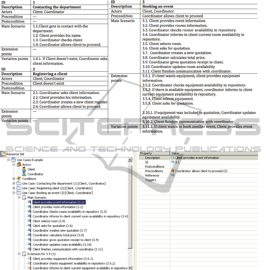
Figure 1: Specification of business use cases for room renting system for events.
Figure 2: General view of the Use Cases Editor.
“To book an event, the client gets in contact with
the company and provides his name. The
coordinator verifies if the client has been previously
registered. If the client register exists, coordinator
allows him to proceed.
On the other hand, if client is new, coordinator
asks his information. Client provides his information
and coordinator creates a new client register. Then,
coordinator finally allows client to proceed.
Just when client is allowed to proceed, he
provides the information of the event and rooms.
After that, coordinator checks the availability of
rooms in the data repository. Then, he informs to the
client the results. With that, client selects the most
appropriate room for him and asks for the quotation.
Coordinator proceeds to create a new quotation,
calculates the total price and gives receipt to client.
Finally, coordinator updates room availability and
client finishes communication with coordinator”.
From the informal description given, three
business processes are identified for the system:
Contacting the department, registering a client and
booking an event.
LessonsLearnedbyusingtheIntegratedDomainModelingToolset
355

3.3 The Components of the Integrated
Domain Modeling Toolset
3.3.1 Use Cases Editor
This tool is meant for creating and defining elements
that compose the business use cases. Furthermore, it
allows constructing the use cases model that will be
used for representing the procedural knowledge
within the IDM approach. Also, it uses natural
language processing libraries.
It is important to clarify that this tool is not
meant for UML Use Case diagram, which is clearly
standardized. Instead, this tool supports an adjusted
use case template that describes business use cases.
From the IDM approach, business use case are
formed by sentences, written in natural language,
that shows step by step how a process is executed,
what the variations are and which actors are
involved. For instance, for each of the business
processes of the example, it was created its
respective business use case specification using the
adjusted use case template that IDM proposes, as
Figure 1 shows.
However, user needs to pay attention to certain
considerations while creating the specification of the
business use case. First, user needs to write
sentences in simple present tense and in a simplest
and unambiguous way possible; although in realistic
way, this might not be always possible. This is more
advisable if ontology is not used.
For example, for the business use case
specification “Booking an event” shown in Figure 1,
the precondition and the step 3.1 were combined in
one sentence in the informal description as “Just
when client is allowed to proceed, he provides the
information of the event”. Clearly, the pronoun “he”
refers to “client” but for the specification of the
business use case using the Use Case Editor, that
pronoun needs to be replaced by “Client”.
Furthermore, it is recommended that user not
define complex sentences. Instead, two use case
steps should be written than one complex. For
instance, in the specification of business use case
“Registering a client” shown in Figure 1: “Client
provides his information and coordinator creates a
new client register”. It should be written as two
steps: “Client provides his information” and
“coordinator creates a new client register” as in the
steps 2.2 and 2.3 respectively.
As shown in Figure 2, this tool allows users to
define different elements for the Use Cases root
element like Actors, Conditions, Use cases and Main
scenario with its steps. Moreover, it enables to
define Composite conditions and alternative
scenarios (Sub Variation and Extension) for main
scenarios.
The attributes that can be defined for Use Cases
root element are Domain, Scope and Ontology.
However, the attribute Ontology just refers to the
technical name of the ontology for the domain.
To start creating the model, the user needs to
right click on the Use Cases root node and select an
element of any of the types shown in the menu. The
menu items shown are: Actors, Conditions and Use
case.
Under the Actors node, it is possible to create as
many actor elements as the user wants. The Actors
element just has Description as attribute.
Under the Conditions node, it is possible to
create Simple and Composite Conditions elements
that will serve as preconditions for the business use
cases. Both types of conditions have as attributes Id
and Operation, but only for Composite Conditions,
the Conditions attribute also needs to be specified.
In order to create composite conditions, the user
needs to consider that it is necessary to have
previously defined two simple conditions. After that,
the user needs to add those simple conditions inside
the Conditions attribute of the composite condition
and finally, select one of the available pre-defined
operator values (OR, XOR, AND).
In Use Case element, user can set the list of
Actors, Description and Id as attributes. Also, it is
possible to set Main Scenario, Sub Variation and
Extension.
Inside the Main Scenario, the user can start
creating its steps, i.e., default event elements.
Moreover, inside the Sub Variation or Extension
element, user can create alternative event elements.
The attributes for event elements are Description,
Id, Postconditions and Preconditions. To set these
attributes, the user shall use the properties view.
The user shall save the model and a file with
extension .usecases will be created. User can open it
with a text editor to see the XMI format it is written
in.
After finishing the creation of the business use
cases, the user can acquire the topological relations
and its graphical representation automatically after
opening the context menu on the use cases model
and selecting “Transform to TFM” option. The Use
Case to TFM transformation tool will be executed
and then, the TFM will be generated. After that, user
can continue with the analysis in the TFM.
3.3.2 TFM Editor
This tool is meant for constructing and representing
ENASE2015-10thInternationalConferenceonEvaluationofNovelSoftwareApproachestoSoftwareEngineering
356
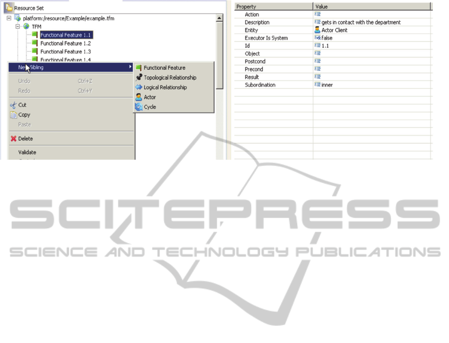
Figure 3: General view of the TFM Editor.
the topological space. After clicking on the option
“Transform to TFM”, as mentioned earlier in
subsection 3.3.1, the Use cases to TFM
transformation tool transforms the use cases model
into TFM model automatically.
TFM shall consist of one or more cycles, at least
two functional features and at least one topological
relationship. It may contain logical relationships as
well.
As shown in Figure 3, the tool allows the users to
edit the generated TFM by adding different types of
elements as Actor, Functional Feature, Topological
Relationship, Cycles and Logical Relationship.
For creating an element, the user shall right click
on the TFM root node and select one of types of
elements mentioned before. To set the attributes for
a specific element the user shall use the properties
view.
Functional Feature element has the following
attributes: Id, Description, Action, Result, Object,
Subordination (inner or external), Precondition,
Postcondition and whether the Executor is the
system.
The Topological Relationship element, which
defines the cause-effect relationship between two
functional features, has the following attributes: Id,
Source and Target. Source and Target attributes are
functional features previously defined.
The Logical Relationship element can be defined
using at least two topological relationships.
Moreover, it has the following attributes: Id,
Operation (AND, OR, XOR) and the Related
Elements, which are the topological relationships
that define it.
The Cycle element has as attributes: Order,
whether it is main and Functional Features. Also, the
Actor element just has Description as attribute.
The user shall save the model and a file with
extension. TFM will be created. It can be opened
with a text editor to see the XMI format it is written
in.
When transforming from use case model to
TFM, the tool takes certain considerations. For
instance, the step 1.4.1 from the business use case
“Contacting the department” shown in Figure 1: “If
client doesn’t exist, coordinator asks client
information”.
First, the tool composes the functional features.
For each of them, the tool set as Id, the Id use case’s
step to whom they refer.
As mentioned before, TFM states that every
functional feature consists of an object action, a
result of this action, an object involved in this action,
a set of preconditions of this action, an entity
responsible for this action and subordination.
So, the tool identifies the object’s action from the
Description of the step. The Description attribute is
fetched automatically from use case’s step. In the
example, the description of the step 1.4.1 is
“coordinator asks client information”.
After that, the tool should recognize the objects
involved in that action. From the example, the
involved objects are: a client, coordinator and client
information. However, the tool currently does not
support this task.
The use case’s actors are considered as entities
responsible of the functional feature. In the example,
the entity responsible for that action is
“coordinator”. It is important to notice that the tool
also verifies if that specified actor is considered in
the list of actors defined for the business use case.
For the exposed case, the business use case
“Contacting the department” has as actors: client and
coordinator; hence, no errors will be displayed.
The tool considers as Preconditions, the
preconditions of the use case's step. From the
LessonsLearnedbyusingtheIntegratedDomainModelingToolset
357

example, the precondition is “client doesn’t exist”.
The default value for Subordination is “inner”
and that is the value that the transformation
considers when transforming to TFM since there is
no way to establish that attribute from the Use Case
Editor.
The setting of cause-effect relations between
functional features represented within the same use
case is straightforward. In this purpose, the tool
follows the order of steps in the definition of the
scenarios.
Every main scenario of use case is an ordered
sequence of functional features. For instance, the
tool will create cause-effect relations between steps
1.1, 1.2, 1.3 and 1.4 for the business use case
“Contacting the department” in Figure 1.
Extensions and Sub Variations help to detect
branching in a TFM:
Extension adds an effect to the functional feature
represented by the step referenced by the
extension. As shown in Figure 1, there are just
two extensions for the business use case
“Booking an event” included in the steps 3.5 and
3.10.
Sub Variation, on the other hand, adds an effect
to the functional feature represented by the
previous step referenced by the sub variation.
Similarly, the selected case study just has two
variations included in the step 1.4 of business
uses case “Contacting the department” and the
step 3.11 of the business use case “Registering a
client”.
Also, no duplicate functional feature is created, i.e.,
functional features represented by the same tuple are
considered the same functional feature and two or
more use cases can include the representation of the
same functional feature.
From the example, the description in step 3.11
and step 3.10.2 is “Client finishes communication
with coordinator”. Therefore, the tool will recognize
the similarity and then, it will create just one
functional feature whose description will be “Client
finishes communication with coordinator”. After
that, it will generate a cause-effect relation between
the functional features of the step 3.10 with the
newly generated functional feature. Similarly, the
tool will create another cause-effect relation between
the new one and the functional feature of the step
3.10.1.
User can continue the analysis from the just
automatically generated TFM model produced by
the transformation of the use cases model.
Therefore, there is no need to construct the TFM
from scratch and because the initial model was
automatically generated from the Use Cases Editor.
Authors agree that the generated TFM is
intuitively illustrated and easily editable, so that any
incompleteness, redundancy or inconsistency could
be corrected. However, user needs to pay attention
to certain considerations while using this tool.
First, IDM suggests several iterations back and
forth between the use cases model and TFM until the
system analyst can verify it is correct.
Moreover, the system analyst shall manually
determine functional feature’s subordination after
acquiring the TFM since the tool currently does not
automate that feature. This can be particularly
necessary when establishing subordination between
functional features from different business use cases.
Finally, currently the object’s action, result of
this action and object involved in this action are
merged into description attribute. Hence, the tool,
when transforming, does not give them
automatically.
3.3.3 TFM Diagram Tool
This tool is a graphical editor for constructing the
TFM’s topological graph.
As mentioned in subsection 3.3.1, after clicking
on the option “Transform to TFM”, the Use Case to
TFM transformation tool transforms the use cases
model into the initial TFM model.
Then, user shall click on “Initialize TFM
diagram” to generate the diagram automatically.
Thereby, the diagram tool displays the generated
TFM in a graph and provides a palette for the user to
continue modeling TFM in diagram form.
This tool allows the users to define TFM in a
diagram form and provides a palette of options for
defining its elements. The elements that can be
defined are actors, functional features, topological
relationships, cycles and logical relationships.
To create elements, the user shall select the
corresponding option from the palette or right click
on the canvas and select the desired element.
All the attributes of the element can be set
directly in the properties view. To add a topological
relationship from the palette, two functional features
needs to be in place first.
Moreover, to create a logical relationship, at least
two topological relationships need to be already in
the diagram. The link option for logical relationships
allows binding the logical relationship to the
topological relationship. Finally, to create a cycle, it
is needed two or more functional features.
As Figure 4 shows, on the left, there is a palette
with available options for the user to model. In the
center, there is a canvas for the diagram. On the
ENASE2015-10thInternationalConferenceonEvaluationofNovelSoftwareApproachestoSoftwareEngineering
358

Table 1: Summarization of suggestions for improvement.
Tool Suggestions for improvement
Use Cases Editor
- Integrate with a tool that supports “declarative knowledge”.
- Improve the handling of validations of Business Use Case.
- Clarify the role of “reference” and “trigger” property when defining steps of the Business Use Case.
- Provide numeration guidelines for elements in the Business Use Case.
TFM Editor
- Implement backward synchronization from TFM and diagram to Business Use Case.
- Improve Business Use Case validation: some topological relationships are generated outside of the main
TFM node.
TFM Diagram Tool - Provide suggestions of cycles for the generated TFM.
right, there are the properties and outline view.
The user shall save the diagram and a file with
extension .tfm_diagram will be created. It can be
opened with a text editor to see the underneath XMI
format it is written in.
User needs to pay attention to certain
considerations while using this tool. First, it is not
possible to automatically acquire the main cycle,
sub-cycles and logical operations. Thus, this has to
be inserted manually by the user. The user, for the
completeness of the main functioning cycle, shall set
the cause-effect relation between functional features
from different use cases since this type of
relationship cannot be determined automatically.
Furthermore, when editing the diagram, the
diagram tool also updates the changes into the TFM
model of the TFM Editor so both artifacts are in
sync. However, when there are errors or changes on
cause-effect relationships in the TFM, the user needs
to return to the Use Cases Editor and make the
corresponding modifications there as well. But since
there is not any backward synchronization between
TFM Editor and diagram tool to Use Cases Editor
implemented yet, the user might lose all those
changes.
4 SUGGESTIONS FOR
IMPROVEMENTS
When performing the usage of the IDM toolset, the
authors were able to successfully acquire a domain
model in a form of TFM, i.e., to acquire a graphical
representation of the business processes (procedural
knowledge) automatically.
The authors find acquiring a graphical
representation of the business process simply and
straightforward.
However, authors found some issues that
consider important to resolve perhaps in further
researches and are presented here as suggestions for
improvements. They are presented here as
suggestions for improvements and summarized in
Table 1.
Notice that authors consider the user practical
usability as the main aspect that makes these
suggestions important. The toolset components
should be enough understandable so the end-user
can work with the tool with low effort to learn the
approach and produce valid and correct TFM
diagrams.
4.1 The Tasks in the Use Cases Editor
Creating business use cases is quite simple. User just
needs to create a new Use Cases model in a new
project and start writing each of the steps that will
compose the Business Use Cases.
As mentioned earlier, it is important that the
domain modeling tool acquires the domain
knowledge that is composed by the declarative
knowledge and procedural knowledge: knowledge
model (dictionary of the domain) for a business
domain (business processes of the domain).
In the IDM approach, ontology is used for
defining the declarative knowledge and Business
Use Cases are used for acquiring the procedural
knowledge of the domain.
Authors agree about the fact that Business Use
Cases provide a formal way to define the procedural
knowledge showing step by step how a business
process of the domain is executed, what the
variations are and which actors are involved.
Nevertheless, currently the IDM approach does
not provide any tool implementation or any
integration with other tool that supports the
declarative knowledge of the domain. So, the user
needs to perform the use case validation against the
declarative knowledge manually.
The IDM approach states that ontology is not
mandatory and encourages the reuse of existing
ontology tools that can help the system analyst in the
validation of use cases to correspond with the
domain ontology.
But still, the lack of support of declarative
knowledge, i.e., integration with any ontology tool
and the automatic use case validation with the
LessonsLearnedbyusingtheIntegratedDomainModelingToolset
359
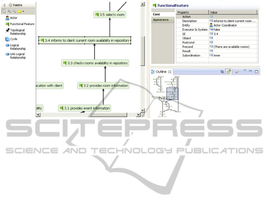
Figure 4: General view of the TFM Diagram Tool.
declarative knowledge, can be pointed out as one of
the most valuable improvements to be done.
Authors believe that constructing or reusing
domain ontology is important for helping the domain
analysis process and validating use cases against
ambiguity and inconsistency problems.
As mentioned before, the validation is a
necessary task to be performed manually by the
system analyst together with the knowledge
engineer. Consequently, since use case steps are
written in natural language, it cannot be guaranteed
that the terms used within the use cases definition
are unambiguous and consistent.
There are some other suggestions of
improvements for the Use Cases Editor.
First, improving handling of validations of use
cases. While performing several tests with the Use
Cases Editor, authors confirm it provides some basic
validations that are launched just after selecting the
“Validate” option in the editor’s main menu.
Nevertheless, any validation over the business
use cases is executed if the transforming TFM
option is selected directly. Apparently, the editor
allows the user to generate TFM even though there
might be problems with the definition of some use
cases.
The authors believe that this can be considered as
a tool bug that can lead to inconsistency problems in
user's work especially if the user has spent a lot of
time and effort in making changes over a generated
TFM with errors that user did not know it was
incorrect at first place. Moreover, this can be
particularly hard to detect for users that are starting
to learn the IDM approach.
As a way of dealing with that issue, authors
suggest that the tool should not allow the user to
generate TFM if no validation has been performed
first. Therefore, the “Transform to TFM”
functionality should not be available if the user has
not validated the model first by clicking on the
“Validate” option.
Otherwise, the tool should always execute the
validations of the use cases before that the
generation of TFM is performed. Then, if there are
any mistakes, it should notify the user. If not, it
should execute the transformation automatically.
Secondly, the tool allows the configuration,
among other properties, of the Reference and
Trigger property when defining steps of the Business
Use Case.
As explained in (Osis and Asnina, 2011a), TFM
does not define those properties as part of the
functional feature definition. Furthermore, in (Šlihte,
2010a) it is not defined as part of the use case
definition; therefore, it is not clear for the authors
what is their role in the tool or in the generation of
TFM.
Although, according to some tests performed
with the tool, the setting of any of those properties
produces an impact over the generation of the TFM
diagram.
In the case of reference attribute, it causes that
the use case step, for which the attribute was
defined, will not be considered as functional feature
in the generation of the TFM model. So, that use
case step is ignored. Furthermore, it creates a cause-
effect relation between the functional feature
obtained from the use case step defined in the
reference attribute and the functional feature
obtained from the following use case step, i.e., the
ENASE2015-10thInternationalConferenceonEvaluationofNovelSoftwareApproachestoSoftwareEngineering
360

use case step located after the use case step with a
defined reference attribute.
In the case of trigger attribute, if set up by the
user, it causes the creation of cause-effect relation
between the functional feature defined in the trigger
attribute and the functional feature generated from
the use case step for which the trigger attribute was
established. This can be particularly beneficial for
establishing the cause-effect relation between steps
from different use cases, i.e., determining functional
features subordination in the generation of TFM.
Currently, the subordination of functional features is
another necessary task to be performed manually by
user.
The authors guess that those properties might be
part of the leveraged functionality provided by the
EMF when developing the tools. But they strongly
recommend its revise for avoiding user’s misuse,
especially since it is open for the users and their
usage might produce unwanted side effects on the
generated TFM. Thereby, unless there is clearly
established its functionality, the authors suggest their
omission.
Finally, as described in subsection 3.3.1, IDM
approach proposes to work with an adjusted use case
template that describes the business use cases. But
that adjusted template does not say anything related
with the numeration guidelines for elements in the
use case.
So, even though, user uses the same numeration
but in different steps for different use cases, the tool
will consider this as an error and complain when it
will validate the model.
Hence, authors recommend establishing
numeration or naming guidelines for use cases and
its steps described in the main scenario, the
extensions and variations. Otherwise, after finishing
the use cases model, the user will be alarmed by a
long list of error messages indicating that the chosen
number for a specific step was already considered in
other step. This can be particularly confusing for
novice users and discourage its usage.
4.2 Task in the TFM Editor
The generation of TFM is quite straightforward. It is
just needed to open the context menu on the use
cases model and selecting the “Transform to TFM”
option. The editor automatically identifies the cause-
effect relations between the functional features by
considering the order, in which the functional
features appear in the business use case description.
Once the generated TFM is in place, adding new
topological elements becomes efficient. The tool
offers the user to correct these initial system’s
objects, functional features or cause-effect relations,
and add new objects or functional features.
Because the IDM approach suggests an iterative
development of the TFM model, the user is able to
see the mapping between the changes in the TFM
and the changes in the TFM diagram. Since they are
in sync, changes in either place (topological space or
topological graph) are automatically affected.
However, the same does not apply if changes in
the use cases source occur after changes in the auto-
generated sources (TFM and TFM diagram). If that
happens, it can cause incompatibility problems when
regenerating TFM from the recently updated use
cases source, i.e., changes in use cases can lead to
backward incompatibility problems because changes
in TFM or TFM diagram are not automatically
reflected in the use case source; thus, all changes in
TFM and TFM diagram, if there are any, will be
lost.
As described in (Šlihte, 2010b), the TFM tool
supports several iterations back and forth between
use cases description and TFM generation until the
system analyst can verify every functional
requirement. So, changes are expected as part of the
process of acquiring the TFM version that satisfies
the user.
However, all the changes in TFM and TFM
diagram will be lost if user generates the TFM again
from the use case editor because all those changes
are not reflected in the Use Cases Editor.
The authors consider this as another essential
aspect to improve in the toolset. Every time, after
changing the use cases’ source and transform it to
TFM, the user will need to remember all those
changes in the auto-generated source and set them
up again into the tool, causing extra job and time
from the user perspective.
On the other hand, when using the TFM editor,
the authors noticed that some topological
relationships were generated outside the main TFM
node. Authors think all the elements automatically
created from the use case source should be allocated
inside the TFM node. Therefore, authors are not sure
about the reason why some elements can be created
automatically outside the main TFM node; thus, they
consider this occurrence as a tool bug.
It is important to mention that novel users might
not notice this error and can start immediately
working on a generated TFM diagram with errors.
The authors can just guess that it might happen
because the use case source had errors that were not
initially detected when transforming to TFM.
Consequently, the tool generates TFM from business
LessonsLearnedbyusingtheIntegratedDomainModelingToolset
361

use cases with errors and all the topological
relationships that had errors were automatically
allocated outside the main node. As suggested
before, authors suggest giving more emphasis to the
validation from the Use Cases Editor to avoid this
kind of incompatibilities.
4.3 Tasks in the TFM Diagram Tool
The tool automatically constructs a TFM’s
topological graph. Again, once the generated TFM
diagram is in place, adding new topological
elements becomes efficient.
The authors just found one suggestion that can
contribute to improve the effectiveness of the tool
when acquiring the TFM model.
As described in (Osis and Asnina, 2011a), in
every topological model of system functioning there
must be at least one directed closed loop (i.e. a
directed closed path). Usually it is even expanded
hierarchy of cycles. This property of the model
enables analyzing similarities and differences of
functioning systems.
The importance of cycles lies in providing a
formal validation. The TFM allows it by cycle
analysis against the actual functioning system in real
life (make sure that all functional features for the
particular business process represented by the
particular cycle are present). Thus, it is possible to
trace through the functional features and see if the
cycle makes sense.
The tool enables the user to manually point the
main functional cycle and to add secondary cycles
(Šlihte, 2010b). However, authors believe that if the
tool provides some sort of mechanism of suggestions
of cycles for the generated TFM, the analyst would
validate at first glance the generated TFM.
Therefore, the validations, additions or changes of
the TFM might be easily pointed out.
5 CONCLUSIONS
The results after using the toolset are as follows. As
a prototype, its main goal for acquiring
automatically the CIM as TFM, as formal domain
model, through the business processes using
business use cases with a model transformation has
been accomplished successfully.
The toolset is intuitively illustrated and allows
modifying models easily, so that the user can correct
any incompleteness, redundancy or inconsistency in
the generated TFM.
Due to its compatibility with MDA standards and
MDA frameworks, the toolset projects itself as a
candidate for integration with other modeling tools
and has a big potential for becoming part of the
MDA life cycle.
The synchronization between the TFM editor and
TFM diagram tool ensures the TFM model keeps
accurate while editing.
However, to become a fully usable toolset and to
introduce it for wider audiences, there are some
considerations that should be taken into account.
First, improve the validations and user
notification messages, primary on the Use Cases
Editor. This can be particularly beneficial for users
that are starting to work with the TFM4MDA
approach. Currently, the Use Cases Editor allows the
user to transform business use cases into TFM even
though there might be some basic errors that should
be corrected before the transformation. The tool
should not allow the user to perform the
transformation if any errors have been founded.
Secondly, provide the synchronization of
changes from the Use Cases Editor to the rest of the
tools. Currently, the synchronization of changes
exits solely between TFM Editor and TFM Diagram
Tool. So, after acquiring the TFM and making some
changes on it, if the user wants to make changes in
the business use cases, all the changes made in TFM
Editor and TFM Diagram Tool will be lost when the
user performs “Transform to TFM”.
Third, because of the limitation of the language
processor used for the implementation of the toolset,
users need to consider reformulating the steps using
simple tense and need to be written as simple as
possible.
Finally, even though, proving the cycles is not
part of the initial transformation of the TFM, authors
believe that it would be a great benefit for users to
somehow see which are the potential cycles. This
functionality can accelerate the process of editing
the TFM because analysts could directly identify
inconsistencies, if there were any.
REFERENCES
Asnina, E & Osis, J 2010, ‘Computation Independent
Models: Bridging Problem and Solution Domains’, in
Model-Driven Architecture and Modeling Theory-
Driven Development, eds J. Osis & O. Nikiforova,
ENASE 2010, 2ndMDA&MTDD Whs., SciTePress,
Portugal, pp. 23 – 32.
Asnina, E & Osis, J 2011, ‘Topological Functioning
Model as a CIM-Business Model’, in Model-Driven
Domain Analysis and Software Development:
Architectures and Functions, IGI Global, Hershey,
ENASE2015-10thInternationalConferenceonEvaluationofNovelSoftwareApproachestoSoftwareEngineering
362

New York, pp. 40 – 64.
BPMN 2.0 2015, Object Management Group: Business
process model and notation (BPMN) 2.0, viewed 5
March 2015, <http://www.omg.org/spec/BPMN/2.0>.
EMF 2015, Eclipse Modeling Framework, viewed 5
March 2015, <http://eclipse.org/modeling/emf/ >.
Gasevic, D, Djuric, D & Devedzic V 2006, Model Driven
Architecture and Ontology Development, Springer,
Heidelberg.
Kossak, F, Illibauer, C, Geist, V, Kubovy, J, Natschläger,
C, Ziebermayr, Th, Kopetzky, T, Freudenthaler, B
& Schewe, K-D 2014, A Rigorous Semantics for
BPMN 2.0 Process Diagrams, Springer.
Linagora 2015, What is MDA? Why concerns BPMN?,
viewed 5 March 2015, <https://research.linagora
.com/pages/viewpage.action?pageId=3639295>.
OMG 2015, OMG: Object Management Group, viewed 5
March 2015, <http://www.omg.org>.
Osis 1969, Topological Model of System Functioning,"
Automatics and Computer Science, J. of Acad. of Sc.,
no. 6, pp. 44-50, 1969.
Osis, J & Asnina, E 2008, ‘A Business Model to Make
Software Development Less Intuitive’, Proceedings of
the 2008 International Conference on Innovation in
Software Engineering, Vienna, Austria, IEEE
Computer Society CPS, Los Alamitos, USA, pp. 1240
– 1246.
Osis, J & Asnina, E 2011a, ‘Topological Modeling for
Model-Driven Domain Analysis and Software
Development: Architectures and Functions’, in Model-
Driven Domain Analysis and Software Development:
Architectures and functions, eds J Osis & E Asnina,
IGI Global, Hershey, New York, pp. 15-39.
Osis, J & Asnina, E 2011b, ‘Is Modeling a Treatment for
the Weakness of Software Engineering?’, in Model-
Driven Domain Analysis and Software Development:
Architectures and Functions, Hershey, New York, pp.
1 -14.
Osis, J & Asnina, E 2011c, ‘Derivation of Use Cases from
the Topological Computation Independent Business
Model’, in Model-Driven Domain Analysis and
Software Development: Architectures and Functions,
IGI Global, Hershey, New York, pp. 65 – 89.
Osis, J, Asnina, E & Grave, A 2007a, ‘MDA Oriented
Computation Independent Modeling of the Problem
Domain’, Proceedings of the 2
nd
International
Conference on Evaluation of Novel Approaches to
Software Engineering (ENASE 2007), Barcelona,
Spain, pp. 66 -71.
Osis, J, Asnina, E & Grave, A 2007b, ‘Formal
Computation Independent Model of the Problem
Domain within the MDA’, Information Systems and
Formal Models, Proceedings of the 10th Internat.
Conference ISIM’07, Silesian University, Opava,
Czech Republic, pp. 47 – 54.
Osis, J, Asnina, E & Grave, A 2007c, ‘A Computation
Independent Modeling within the MDA’, IEEE
International Conference on Software-Science,
Herzlia, Israel, no. E3021, pp. 22 – 34.
Osis, J, Asnina, E & Grave, A 2008a, ‘Computation
Independent Representation of the Problem Domain in
MDA’, e-Informatica Software Engineering Journal,
vol. 2, no. 1, pp. 29-46, viewed 5 March 2015,
<http://www.e-informatyka.pl/wiki/e-Informatica>.
Osis, J, Asnina, E & Grave, A 2008b, ‘Formal Problem
Domain Modeling within MDA’, Communications in
Computer and Information Science (CCIS), Software
and Data Technologies, Springer-Verlag, Berlin,
Heidelberg, vol. 22, pp. 387 - 398.
Recker J 2012, ‘BPMN Research: What we Know and
What we Don’t Know’, viewed 5 March 2015,
<http://eprints.qut.edu.au/53599/1/BPMN2012_-
_Recker_Keynote.pdf>.
Šlihte, A 2010a, ‘Implementing a Topological Functioning
Model Tool’, Scientific Journal of Riga Technical
University, vol. 43, pp. 68-75.
Šlihte, A 2010b, ‘The Specific Text Analysis Task at the
Beginning of MDA LifeCycle’, Databases and
Information Systems Doctoral Consortium, vol. 757,
no. 5-7, pp. 11-12.
While S 2004, Introduction to BPMN, viewed 5 March
2015, <http://yoann.nogues.free.fr/IMG/pdf/07-04_
WP_Intro_to_BPMN_-_White-2.pdf>.
LessonsLearnedbyusingtheIntegratedDomainModelingToolset
363
