
Topology Optimisation of Rotating Automation Components for
Machine Tools – Methodology, Cost Effectiveness and Examples
Gerhard Kehl, Paul Jickeli, Martin Schietinger and David Blank
University of Applied Sciences, Faculty of Engineering Management, Esslingen, Germany
Keywords: Finite Element Simulation, Topology Optimisation, Simulation Costs, Return on Investment.
Abstract: Light weight constructions possess a variety of general benefits in application, such as higher energy
efficiency, increase of acceleration or payload. But especially the reduction of costs over the entire product
life cycle is increasingly in the focus. By application of topology optimisation for rotating automation
components a significant improvement is possible. On the other hand any simulation effort has to be judged
as an entrepreneurial action for which a return on investment (ROI) has to be ensured. The simulation tasks,
results and in conclusion the ROIs for some exemplary optimisations in the field of manufacturing machines
are presented and assessed as success stories for the use of simulations in practice.
1 INTRODUCTION
The application of lightweight construction offers a
variety of benefits, such as improved energy
efficiency, acceleration and increased payloads. In
addition to the use of lightweight raw materials and
lightweight manufacturing methods, there is also
potential in the area of structural design
optimisation. This can be tapped by employing
computer aided optimisation methods (Klein, 2013).
Some finite element software packages offer
integrated topology optimisation functionality for
this purpose. They are useful for the simulation of
structural components during the concept
development and design phases. ANSYS and
ABAQUS e.g. support the consideration of static
load cases to enable the development of load
efficient structures.
Initially, it is important to understand the effects
of different load cases in order to be able to optimise
structural components that are used in machine tools
(Brandenberger, 2004). Apart from the consideration
of load bearing structural components (e.g. machine
beds), the study of automation components such as
tool changers, tool magazines and pallet changers
might also be economically promising (Keller,
2005). If these components represent the
unproductive secondary processing time and set-up
time of machine tools, they promise improvements
in movement in addition to the material and energy
savings.
2 BASELINE INVESTIGATION
Firstly, topology optimisation is carried out and
discussed for stationary 2D rectangular element
models (according to the idea of Schumacher, 2005
and 2011), after which the observations will be
extended to rotating 2D models. Then some practical
applications are presented. The following boundary
conditions apply for the 2D rectangular model:
Design space: Height 100 mm, width 50 mm.
The design space is discretised with about 30,000
8-node quadratic elements.
The two lower corners each contain a fixed
point.
The force application point is 75% of the height.
All forces are introduced in the plane, have the
same value and each force is acting in the
positive coordinate direction.
As an optimisation constraint, the mass reduction
is defined such that 20% of the design space
should be filled with material.
The end goal is to maximize the static rigidity.
Topology optimisation is carried out with the
following load cases:
a) Horizontal force
b) Vertical force
c) Horizontal and vertical force applied
simultaneously
d) Horizontal and vertical force applied
sequentially with equal weighting to optimise
the structure
441
Kehl G., Jickeli P., Schietinger M. and Blank D..
Topology Optimisation of Rotating Automation Components for Machine Tools – Methodology, Cost Effectiveness and Examples.
DOI: 10.5220/0005501904410446
In Proceedings of the 5th International Conference on Simulation and Modeling Methodologies, Technologies and Applications (SIMULTECH-2015),
pages 441-446
ISBN: 978-989-758-120-5
Copyright
c
2015 SCITEPRESS (Science and Technology Publications, Lda.)
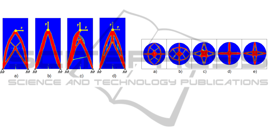
Figure 1 shows the obtained structures for all
four optimisations which show many differences.
The structures of a) and b) are plausible in view of
load efficiency. It is also apparent that the structure
d) clearly results from the superposition of a) and b).
Interestingly, however, structure c) is asymmetrical
and only suitable for the simultaneous occurrence of
the horizontal and the vertical force in the assumed
directions. However, the structure c) is not suitable
for the exclusive occurrence of either the horizontal
force or the vertical force, as well as for the case that
one of the two forces is inverted.
Figure 1: Topology optimisation for 2D rectangular
models with different load cases.
From this baseline investigation, the important
finding is that the optimised geometry has a high
sensitivity to the load cases applied. However this
could be overcome by providing the structure with
some initial geometry constraints to ensure a
sensible outcome. Furthermore, for a valid optimised
structure a load case needs to be applied in which all
loads are considered.
3 STUDIES WITH ROTATING
SYSTEMS
Topology optimisations are performed and then
discussed for 2D circular discs with point masses.
The technical data is based on practical
implementation and the following boundary
conditions apply:
Design space: Homogeneous, massless disc with
a diameter of 500 mm.
The design space is discretised with about 30,000
8-node quadratic elements.
The disc centre is modelled as rigidly fixed.
The four identical point masses (m = 1 kg) are
arranged symmetrically on the periphery of the
disc at 90 ° intervals.
Also as previously, as an optimisation constraint,
the mass reduction is defined such that 20% of
the design space should be filled with material.
As before the final aim is to maximize the static
rigidity.
Topology optimisation is carried out with the
following load cases:
a) Linear acceleration with 2g horizontally
b) Linear acceleration with 2g vertically
c) Angular acceleration α = 720°/ s
2
d) Angular speed ω = 360°/s
e) Combined load case of: a), b), c) and d) with a
load case weighting vector of (2,2,1,1)
Figure 2 shows the differences between the
optimised structures obtained for the given load
cases of the rotating disc.
Figure 2: Topology optimisation with homogenous 2D
circular discs with four equally spaced point masses at the
extremities.
The structures for a) to d) are plausible in view
of load efficiency. Structure b) is simply a 90 degree
phase change from structure a). Structure e) is
created by superposition of the structures a) to d)
and is optimal with reference to the given laod cases
and weighting.
Such optimisation results can often be implemented
in practical structural design. An initial presentation
of the methodology in more detail follows below.
This will then be applied to examples from the
machine tool industry with respect to rotating
automation components such as tool changers, tool
magazines and pallet changers, where this method
in particular might be economically promising.
4 METHODOLOGY FOR
TOPOLOGY OPTIMISATION
Topology optimisations with combined load cases
are useful when dealing with real problems, with the
ultimate aim being practical application of the
solutions found. For this purpose, the following
procedure has proven itself:
1. In machine tools, a variety of tools and work
piece pallets with standardised mechanical
interfaces can be used. The central basic body
SIMULTECH2015-5thInternationalConferenceonSimulationandModelingMethodologies,Technologiesand
Applications
442
of the rotational automated moving component
normally comprises of regular geometric
repetitions. The aim is to keep the analytical
model small and thus shorten the optimisation
procedure. The first thing to consider is the
ability to use the symmetry conditions (mirror
symmetry, axial symmetry and cyclic
symmetry). It should be noted that the
symmetry always relates simultaneously to
geometry and loads.
2. The next step is to determine whether a
simulation by 2D or 3D model is appropriate.
A 2D model can significantly shorten the
calculation process. 3D models should be
applied to the topology optimisation only when
absolutely necessary. This happens for
example, if forces are not applied within the
plane considered, but in a parallel plane some
distance away or perpendicular to the plane.
3. Static load cases should be solved individually
to determine whether loads and boundary
conditions are reasonably defined. Stresses and
deformations have to be determined and
compared for each load case. If there are load
cases that do not contribute significantly to a
combined load case, these load cases may be
neglected in the topology optimisation.
4. Next, the topology optimisation is performed
with each load case. Is the optimised topology
solution sensible with respect to the loads
applied in the load case?
5. Based on the previous results, the weighting of
the load cases for the combined load case is to
be determined. The default could be an equal
weighting of all load cases, but the weight
function should at least be reasonably varied
for trial purposes.
6. Even if the target mass for the optimised
component is known exactly, it is
recommended that the mass reduction be
changed for testing purposes. This could lead
to significantly different structures that provide
more ideas for the design implementation of
the results in practice.
7. If possible, topology optimisations should be
performed with different optimisation
algorithms for comparison (with ANSYS: OC
and SPC).
5 COST-EFFECTIVENESS OF
TOPOLOGY OPTIMISATION
Overall, this approach has been applied in a number
of topology-optimised components to reduce costs
and improve the characteristics of the component
such as weight, inertia and stiffness. Subsequently,
three components will be presented. The examples
of the successful application for 2D or 3D
optimisation of rotating automation components for
machine tools are:
Double gripper arm of a tool changer for a
grinding machine (2D)
Tool magazine for a grinding machine (3D)
Double gripper arm for a tool changer of a
machining centre (3D)
For the overall goal of reducing costs in the
context of the entire product life cycle (Nyhuis, 2009
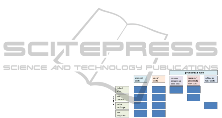
and Wiendahl, 2010), Figure 3 shows the
effectiveness of the topology optimisation of various
machine tool components with regard to the usual
types of costs considered (Witt, 2006). This proves
to be critical to the assessment of the soundness of
topology optimisation when involving machine
utilization by the user.
Figure 3: Effectiveness of the topology optimisation with
regards to the type of costs.
A topology optimisation on a tool changer with
the aim of reducing mass can influence material
costs, but also the operating energy costs.
Furthermore the production costs of a machining
centre with this weight-reduced tool changer are
favourably influenced by more rapid tool changes.
In the topology optimisation of a tool magazine
however, there is usually no reduction in production
costs to be substantiated, because the tool magazine
movement happens isochronical to machining
processes.
6 DOUBLE GRIPPER ARM OF A
TOOL CHANGER FOR A
GRINDING MACHINE
In this case the tool changer arm conducts rotary as
well as linear movements for every tool change.
TopologyOptimisationofRotatingAutomationComponentsforMachineTools-Methodology,CostEffectivenessand
Examples
443
Therefore, a part with reduced mass and reduced
mass moment of inertia reduces the secondary
processing time.
As all relevant forces lay within the plane
considered, a 2D topology optimisation was
sufficient. The topology optimisation was conducted
with a combined load case containing the following
load cases:
a) Linear acceleration (1g horizontally)
b) Gravitational force (1g vertically)
c) Angular acceleration α = 180°/ s
2
d) Angular speed ω = 90°/s
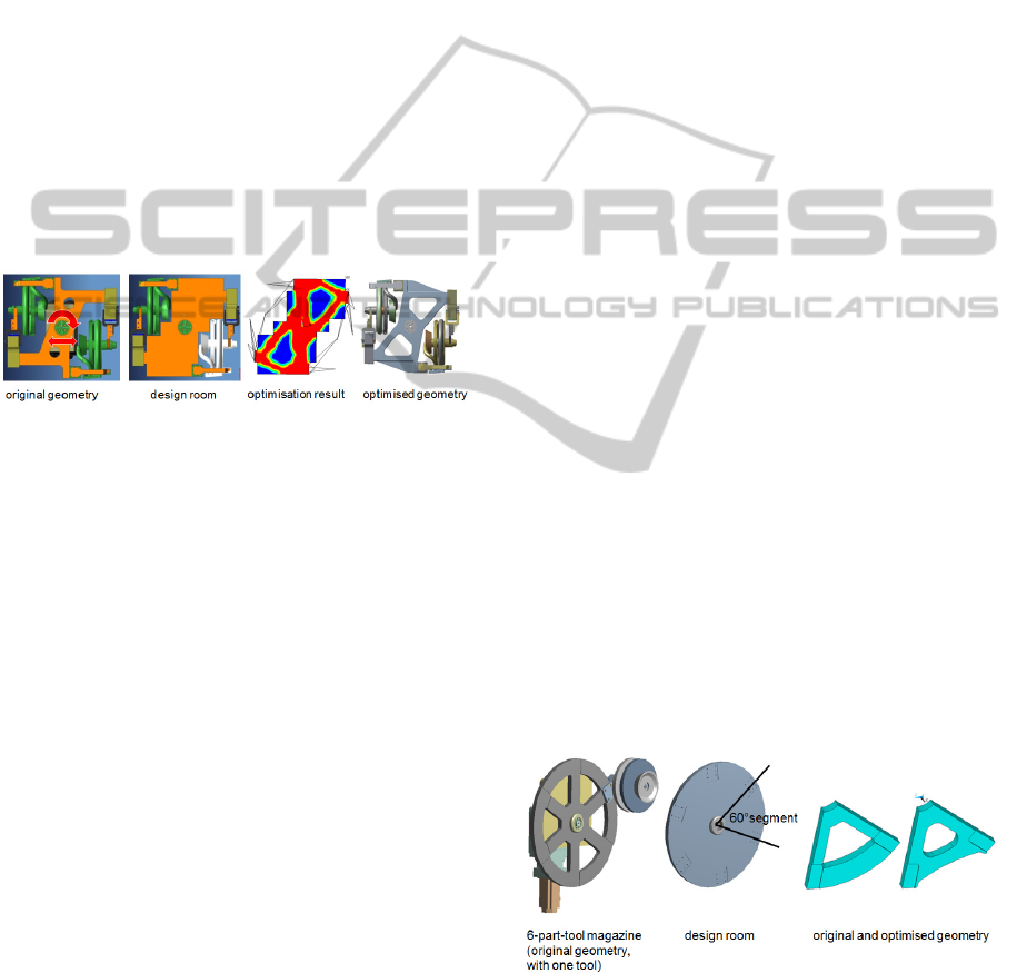
The optimisation result obtained from the design
room was used as the basis for an optimised
geometry. Final calculations showed about 35%
increased stiffness for the same mass compared to
the original geometry of the grinding wheel changer
(Figure 4).
Figure 4: Topology optimisation of a tool changer of a
grinding machine.
Although a stiffening is advantageous, another
alternative was examined. This provided the same
stiffness with a 27% lower mass and a 32% lower
moment of inertia. This made increased linear and
rotational accelerations possible, while using the
same drive equipment. A detailed cost-benefit
analysis was made for this topology optimisation.
This was judged as an entrepreneurial action, for
which a ROI (return on investment) can be
determined. The analysis yielded the following
results:
The grinding machine manufacturer had to
invest an initial one-off € 834 development costs
(including staff for analysis and design, software,
hardware, equipment costs) for the topology
optimisation of this component. The machine
manufacturers benefits initially by the reduction of
material costs by € 33 per grinding machine.
Furthermore the machine user registers a
productivity gain of € 152 per grinding machine for
a duration of 10 years. Thus, from a macroeconomic
point of view, the payback of this amount is received
with five machines. However, for this type of
machine, a total of 1000 units are planned, this
topology optimisation provides a surplus of
approximately € 184,166 in the long term. The
majority of the profit goes to the users of these
grinding machines (€ 152,000), but the machine
manufacturer gains a profit as well (€ 32,166).
While it remains uncertain whether the machine
user is ready to pay in advance for the productivity
growth through an investment, an increase in
efficiency of the grinding machine due to this
optimisation would strengthen the market position of
the machine manufacturer over the competitor’s
(Jickeli, 2014).
7 TOOL MAGAZINE FOR A
GRINDING MACHINE
The disc-shaped tool magazine shown in Figure 5
supplies six different grinding wheels for a grinding
machine controlled by a forward timing device. Due
to the placement of the tool magazine disc in the
vertical plane and projecting tool holders with
grinding wheels, gravity loads apply in a plane
parallel off-set to the disc plane such that a 3D
model is required. The calculation expense can be
reduced by neglecting the load case "angular
acceleration" by symmetry conditions (6 x 60 °).
Even a reduction to a 30° segment would have been
possible. Using topology optimisation load-oriented
grooves in the disc and material savings on the outer
contour, an increase in the stiffness-to-mass ratio of
29% was realised. Manufacturing as a cast part thus
shows reduced material costs. The mass moment of
inertia was reduced by 24%. A reduction in the chip-
to-chip time was not found in practice however, as
the motion of the tool magazine can be performed
simultaneously during machining. However, the
reduced driving torque required results in energy
savings during operation.
Figure 5: Topology optimisation of a tool magazine of a
grinding machine.
The cost-benefit analysis for this component
yielded the following results: For the topology
optimisation of this component € 549 development
SIMULTECH2015-5thInternationalConferenceonSimulationandModelingMethodologies,Technologiesand
Applications
444
costs (including staff for analysis and design,
software, hardware, equipment costs) were assumed.
This can be compared with a material cost reduction
of € 47 per grinding machine. Surprisingly, the
energy savings due to reduced mass moment of
inertia is calculated as less than € 1, despite taking
10 years of operation into account. One reason for
that is, that the inertia of the drive itself is a multiple
of the inertia of the optimised tool magazine.
Nevertheless, this measure makes sense
economically from a quantity of twelve units, even if
the payback time due to lack of relevance for chip-
to-chip time clearly occurs later, compared to double
gripper arm of the tool changer. It is still
indisputable, based on the planned sales, that this
optimisation is the right decision from an
entrepreneurial point of view (Schietinger, 2014).
8 DOUBLE GRIPPER ARM OF A
TOOL CHANGER FOR A
MACHINE CENTRE
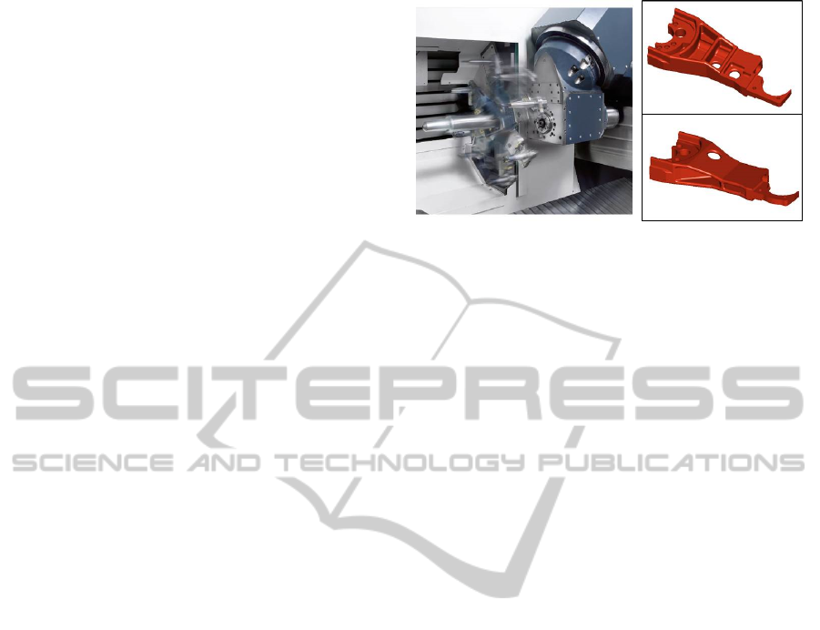
The double gripper arm in Figure 6 provides the
automated exchange of cutting tools between a tool
magazine and spindle within a machining centre, via
rapid linear and rotary movements. The machine by
Gebr. Heller Maschinenfabrik GmbH (HELLER
MCH 280C) can handle very heavy tools of up to 35
kg during a tool change and reaches a chip-to-chip
time of approximately 6.8 seconds.
The aim was to investigate how to further reduce
the chip-to-chip time, but above all to increase the
reliability of the tool change, so that jamming of
tools in the spindle or in the tool supply position is
ruled out under all operating conditions.
Therefore, a topology optimisation of the
geometry has been applied with cyclic symmetry (2
x 180°), so that only the half models of the double
gripper arm are shown. 3D models were considered,
since in addition to the already known load cases of
gravitational force and rotational movement, there
are also significant extraction forces from the tool
interface of the clamping system. These forces apply
in axial direction of the tool and are therefore out of
plane.
As a result of the topology optimisation and
redesign, the component on the bottom right of
Figure 6 shows increased stiffness-to-mass ratio of
21% for typical operating loads compared to the
original component (top right). Additionally, there
was a 19% increase in fatigue resistance, thus
increasing the reliability of the tool change.
Figure 6: Double gripper arm: Function and half models of
the original / optimised component.
9 CONCLUSIONS
Rotational motion components in machine tools
often occur in automation solutions for tools and
work piece flow. Systematic topology optimisation
is a way to improve their technical and economic
characteristics. However, they have to be justified as
economical business decisions in advance. A means
for this is the consideration of the amortisation of
topology optimisations. This can occur at different
unit numbers for various components due to the
influence of cost types. Experience has shown that
the optimisation of components for reduced primary
processing times, secondary processing times, and
set-up times often turns out to be commercially
successful, even in small quantities.
REFERENCES
Klein, B., 2013. Leichtbau-Konstruktionen. Springer
Vieweg-Verlag Wiesbaden.
Brandenberger, M., Kehl, G., 2004. Coupled Simulation
using FEM, MBS and Control Simulation Tools using
the Example of a Machine Tool. In: Proceedings of the
NAFEMS Seminar Mechatronics in Structural
Analysis, Wiesbaden.
Keller, K., Kehl, G., 2006. Coupled FE Analysis of
Structure and Control of High Dynamic Machine
Tools considering the Machining Centre HELLER
MCH 250 as an Example. In: Proceedings of the
PERMAS Users Conference, Strasbourg.
Schumacher, A., 2005. Optimierung mechanischer
Strukturen – Grundlagen und industrielle
Anwendungen. Springer-Verlag Berlin Heidelberg.
Schumacher, A., Ortmann, C., 2011. Topology
Optimization – Research State of the Art. Proceeding
of the Automotive CAE Grand Challenge 2011,
Hanau.
TopologyOptimisationofRotatingAutomationComponentsforMachineTools-Methodology,CostEffectivenessand
Examples
445

Nyhuis, P., Wiendahl, H.-P., 2009. Fundamentals of
Production Logistics Theory, Tools and Applications.
Springer-Verlag Berlin Heidelberg.
Wiendahl, H.-P., 2010. Betriebsorganisation für
Ingenieure. Hanser-Verlag München.
Witt, G., 2006. Taschenbuch der Fertigungstechnik.
Hanser-Verlag München.
Jickeli, P., 2014. Strukturoptimierte Bauteile für reduzierte
Nebenzeiten von Werkzeugmaschinen – konstruktive
Gestaltung und Wirtschaftlichkeitsbetrachtung.
Bachelor thesis at the University of Applied Sciences
Esslingen.
Schietinger, M., 2014. Strukturoptimierung von
Werkzeugmaschinenmagazinen mit Wirtschaftlich-
keitsbetrachtung. Bachelor thesis at the University of
Applied Sciences Esslingen.
SIMULTECH2015-5thInternationalConferenceonSimulationandModelingMethodologies,Technologiesand
Applications
446
