
Numerical Analysis on Water Hammer Characteristics of
Rocket Propellant Filling Pipeline
Xiang Youhuan, Zhang Ping, Zhang Hui and Bai Fengtian
Technical Department, Taiyuan Satellite Launch Center, Taiyuan, China
Keywords: Propellant Filling System, Water Hammer, Flowmeter, Filling Accuracy.
Abstract: In order to investigate the water hammer problem of the filling pipeline during the rocket propellant filling
process of the spaceflight launch site, the simulation calculation model and the real experimental system is
established. It researches the water hammer characteristics of the filling pipeline, and analyses the law of
pressure change when water hammer occurs. The improved schemes are proposed in this paper, and the
simulation calculation and real experiment are carried through for the proposed schemes. It also carries
through data analysis for the simulation and experimental results. The results show that the proposed
scheme can effectively reduce the water hammer effect of the pipeline during the filling process, improve
the rocket propellant filling accuracy and enhance the security and reliability of the system.
1 INTRODUCTION
The rockets propellant filling system is an important
part of the spaceflight launch site. It’s stability
security and reliability is very important for the
success of the spaceflight tasks. Because of risk and
particularity of the propellant work, safety credibility
and precision is the basic requirement for the filling
system (Xiang, 2014).
The filling pipeline is a kind of key assembly of
the rocket propellant filling system, it can provide
routeway for the propellant transporting from the
storehouse horizontal tank to the rocket tank, and it’s
stability could impact the filling accuracy and the
security and reliability of the system. The water
hammer is a water power phenomena in the pipeline
that the water flow rate changed suddenly, leading to
the pressure rise and fall sharply, caused by some
external reasons, such as the valve suddenly open or
close. In the process of rocket propellant filling in the
spaceflight launch site filling system, it often appears
the case that pressure gauges get full range, and it is
far more than the normal working pressure range. It
is a potential hazard.
The water hammer can damage equipment,
reduce the safety and reliability of the system. It also
can cause violent vibration of pipeline, result in
measurement error for the vortex-shedding flowmeter
(Yang, 2004). That will lead to the filling error of
rocket propellant higher and reduce the real filling
precision. Therefore, it requires analysis and research
on water hammer in the filling system, to put forward
effective improvement measures. It is of great
significance for enhancing the propellant filling
precision and ensuring the complete success of rocket
launch.
At present, there are no special studies on water
hammer effect based on the pipeline of rocket
conventional propellant filling system. However, a
lot of research works have been carried out in the
aspects of water hammer in rocket engine system and
some of the other system.
In literature (Yan, 2012), Yan Zheng studies the
water hammer problem of the spacecraft propulsion
system in the processes of priming and shutdown. On
the basic of the established simulation model of the
spacecraft propulsion system, the simulation research
was conducted and the suppression effect of water
hammer for the orifice and bent duct was analyzed.
The result show that the frequency of water hammer
is lower in the process of priming than that in the
process of shutdown, and the peak pressure of water
hammer in the process of shutdown is higher than
that in the process of priming. Both the bend duct and
the orifice can markedly suppress the pressure in the
process of priming, but the suppression effect of
water hammer is weak in the process of shutdown. In
literature (Lin, 2008), Lin Jing-song researches the
fluid transients of the propellant pipes after the liquid
rocket engine shut down, and carries out numerical
337
Youhuan X., Ping Z., Hui Z. and Fengtian B..
Numerical Analysis on Water Hammer Characteristics of Rocket Propellant Filling Pipeline.
DOI: 10.5220/0005505703370343
In Proceedings of the 5th International Conference on Simulation and Modeling Methodologies, Technologies and Applications (SIMULTECH-2015),
pages 337-343
ISBN: 978-989-758-120-5
Copyright
c
2015 SCITEPRESS (Science and Technology Publications, Lda.)
simulation of water hammer in shutting liquid rocket
engine based o n the method o f characteristic line.
The correctness of the simulation results was
approved by comparison with the experiment data. It
also calculates and analyzes the relationship between
two locations that were in front of the closing valve
and on the end of the pressure measuring pipe when
the length and diameter of the pressure measuring
pipe were changed. In literature (Nie, 2003), Nie
Wan-sheng researches the pressure and the flow
transients characteristic when the liquid rocket engine
system shut down based on the method of finite
difference characteristic line. The water-hammer
phenomenon is analyzed in literature (Liu, 2010)
based on the method of characteristic line, according
to the actual construction of liquid hydrogen filling
system. It proposes a useful method to reduce the
peak pressure of water-hammer based on the analysis
results, and it provides theory foundation for design
liquid hydrogen loading system. However, it does not
take the influence of pipeline accessories such as
filter and flowmeter into account, so the precision is
not high.
The rest part of this paper is organized as follows:
Section 2 analyzes water hammer phenomena of the
filling system. The mathematics model is established
in section 3. The experimental results are analyzed in
section 4. Finally, section 5 makes the conclusions.
2 ANALYSIS OF FILLING
SYSTEM WATER HAMMER
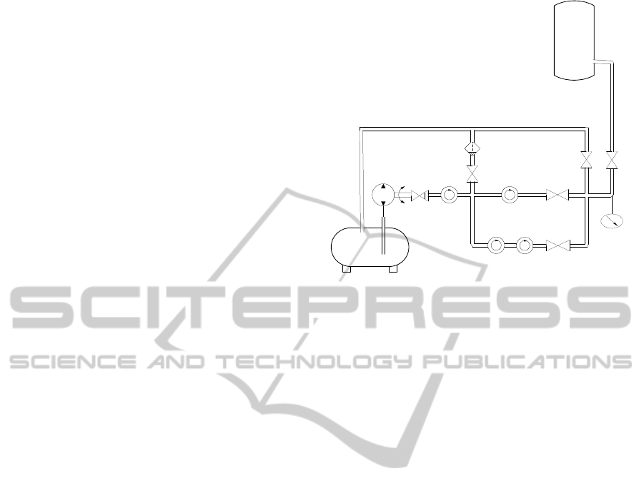
The process diagram of the propellant filling system
is shown in Fig.1. As shown in the Fig, the
equipments such as except the rocket tank are all
located in the pump room of the filling storehouse
and on the same horizontal plane. The rocket tank are
vertically located on the launch pad and on the other
horizontal plane. The height from the 125# valve to
the filling port of the rocket oxidizer tank is 30 meter
or so, and they are connected together through the
filling pipeline. In the process of filling, the state
before interstage conversion is: the frequency of the
pump inverter is 50Hz, the opening of the electric
control valve is 30%, the state of the 134# and 124#
valve is open, and the state of the 125# valve is close.
At the time of interstage conversion, the program
control process is: open the 125# valve, delay 1
second, after that close the 124# and 134# valve. In
the process, the 121# valve has been open, the 122#
valve has been close, the frequency of the pump
inverter has been 50Hz, and the opening of the
electric control valve has been 30%.
Pressure
Gauge
P1
Flowmeter
L1
Pump
Flowmeter
L2
Flowmeter
L3
Flowmeter
L4
125#
124#
Rocket tank
Outlet
134#
Inlet
DT4
121#
122#
Figure 1: Process diagram of the filling system.
From analysis we can know, when open the 125#
valve, the fluid in the vertical pipeline instantly lose
the upward lift force, then it begin to fall under the
action of gravity and achieve maximum quickly. The
instant downward gravity can cause water hammer of
the propellant filling pipeline. When water hammer
occurs, the pipeline nearby 124# valve severe
vibration and engender blare, the valve interface
emits yellow smoke that shows slight leakage occurs
on the interface, and range of the pressure gauge P1
achieves full scale.
From the data recorded in the real filling process,
the pressure of the liquid pipeline is 0.24MPa before
water hammer happening. When water hammer
occurs, the peak pressure of liquid pipeline is more
than 3MPa. It is obvious that great changes have
taken pace for the pressure of liquid pipeline. The
biggest difference is 15 times, and the water hammer
peak pressure is far more than the design pressure. It
can cause the equipment damaged more easily and
increase the probability of the system failure.
3 ESTABLISH MATHEMATICS
MODEL
3.1 Basic Differential Equation of
Water Hammer
The theoretical basic of the basic equation of water
hammer is the law of mechanics and continuous
principle of water flow movement, including motion
equation and continuity equation. It is the basic of the
analysis and calculation of the hydraulic transient,
SIMULTECH2015-5thInternationalConferenceonSimulationandModelingMethodologies,Technologiesand
Applications
338

containing motion equation and continuity equation
expressed in differential equation. It also reflects
changing rule of water head and flow velocity of
instability flow in the process of hydraulic transient
(Lin, 2007).
The continuous differential equation of water
hammer is as follow:
0sin
2
s
v
g
c
v
s
h
v
t
h
(1)
The motion differential equation of water hammer is
as follow:
0
2
vv
D
f
s
v
v
t
v
s
h
g
(2)
In the above formula, v and h respectively express
the flow velocity and piezometric head when the
water hammer occurred. D, f, g respectively express
the pipe diameter, pipe friction coefficient,
acceleration of gravity. θ is the angle between
pipeline and horizontal plane, c is the water hammer
wave velocity, s is the distance, t is the time.
Because of considering the frictional head loss,
the basic differential equation of water hammer is a
first order quasilinear hyperbolic partial differential
equation, and contains two dependent variables and
two independent variables. It is very difficult to solve
the equations.
3.2 Solve Basic Differential Equation of
Water Hammer by Method of
Characteristic Line
The method of characteristic line firstly changes the
partial differential equation into ordinary differential
equation along the characteristic line, and then
changes into first order finite difference equation for
obtaining the approximate solution. It can solve the
water hammer problem of complicated piping system
and boundary conditions, and the calculation
accuracy is high. (Liu, 2005), (Wu, 2002)
The parameter uses x instead of s in formula 1
and formula 2, and this two formulas are carried
through linear combination with arbitrary unknown
parameters λ1. Then we can get the formula as
follow:
0
2
sin)(
)(
1
1
1
2
1
D
vfv
v
g
v
x
v
t
h
g
c
v
x
v
t
v
L
(3)
According to the algorithms of compound
function, and meet the conditions:
1
2
1
g
v
g
c
v
dt
dx
, we can convert formula
3 into ordinary differential equation with unknown
parameters v and h by selecting two value of λ1. The
formula is as follow:
0
2
sin
11
D
vfv
v
dt
dh
dt
dv
(4)
In the above formula,
c
g
1
, that is, λ1 are two
different real number, and
cv
dt
dx
.
By respectively taking the two values of λ1 into
formula 4, we can get equivalent two ordinary
differential equations. Using C+ and C- respectively
express characteristic line of two directions, the
equations are as follows:
Along C+:
cv
dt
dx
gD
vcfv
v
dt
dv
g
c
dt
dh
0
2
sin
(5)
Along C-:
cv
dt
dx
gD
vcfv
v
dt
dv
g
c
dt
dh
0
2
sin
(6)
In view of C+ characteristic line, we can get the
following formula by adopting the finite difference
form.
0
2
sin
111
11
iii
ipiipi
vv
gD
xf
tv
vv
g
c
hh
(7)
In view of C- characteristic line, we can get the
following formula by adopting the finite difference
form.
0
2
sin
111
11
iii
ipiipi
vv
gD
xf
tv
vv
g
c
hh
(8)
NumericalAnalysisonWaterHammerCharacteristicsofRocketPropellantFillingPipeline
339
The following are the steps that using the
characteristic line to solve the water hammer
problems. The first step: the partial differential
equation that can’t directly to solve should be
changed into a specific form of ordinary differential
equation, namely characteristic line equation. The
second step: carrying through integral calculus for
the ordinary differential equations, getting the
approximate algebraic integral formula, namely
finite difference equation. The third step: according
to the finite difference equation and bound condition
equation of piping system to calculate.
3.3 Establish Calculation Model
The mathematical model of the rocket propellant
filling system is established by the Flowmaste
software, taking the influence of the equipments into
account. The equipments include storehouse
horizontal tank, pump, flowmeter, pipeline, valve,
regulating valve, filter, etc. The equipment
parameters use the data in the actual product manuals.
The physical parameter of fluid N
2
O
4
at the
temperature of 20℃ is: viscosity μ=0.4189×10
-3
Pa·s,
ρ=1.446g/cm
3
, saturation pressure Ps=0.096MPa.
The calculation formula of water hammer wave
velocity is (Xu, 2012):
DEK
K
c
1
. In
the formula, K is the fluid bulk modulus, ρ is the
fluid density, E is the piping materials elastic
modulus, D is the pipe diameter,
is the pipe wall
thickness.
According to the calculation formula of water
hammer wave velocity, the water hammer wave
velocity of oxidant pipeline in the propellant filling
system can be get through calculation, c=850m/s. In
the calculation model, we set pipeline that length
longer than 40m as elastic pipeline, the rest as rigid
pipeline.
On the basis of water hammer wave velocity and
elastic pipeline length, in order to make the time step
to meet the transient stability conditions which is
cx
t
1
, we set the time step of transient
calculation Δt=0.00125s.
4 EXPERIMENTAL RESULT
ANALYSIS
For further analyzing the generating mechanism of
water hammer effect in the filling system and the
pressure change law when water hammer occurs
influenced by the filling control process, and
researching the scheme that can reduce the water
hammer effect in the filling system, the simulation
calculation and real experiment are carried through.
The simulation calculation is carried through
according to the method of mathematics model
mentioned in the above section. The real test scheme
is designed for the real experiment, the state and
parameter is set according to the real filling. We
adopt the pressure acquisition system to capture
water hammer phenomena in the filling system, and
record pressure change law when water hammer
occurs in real time. The position of pressure gauge P1
is shown in Fig.1.
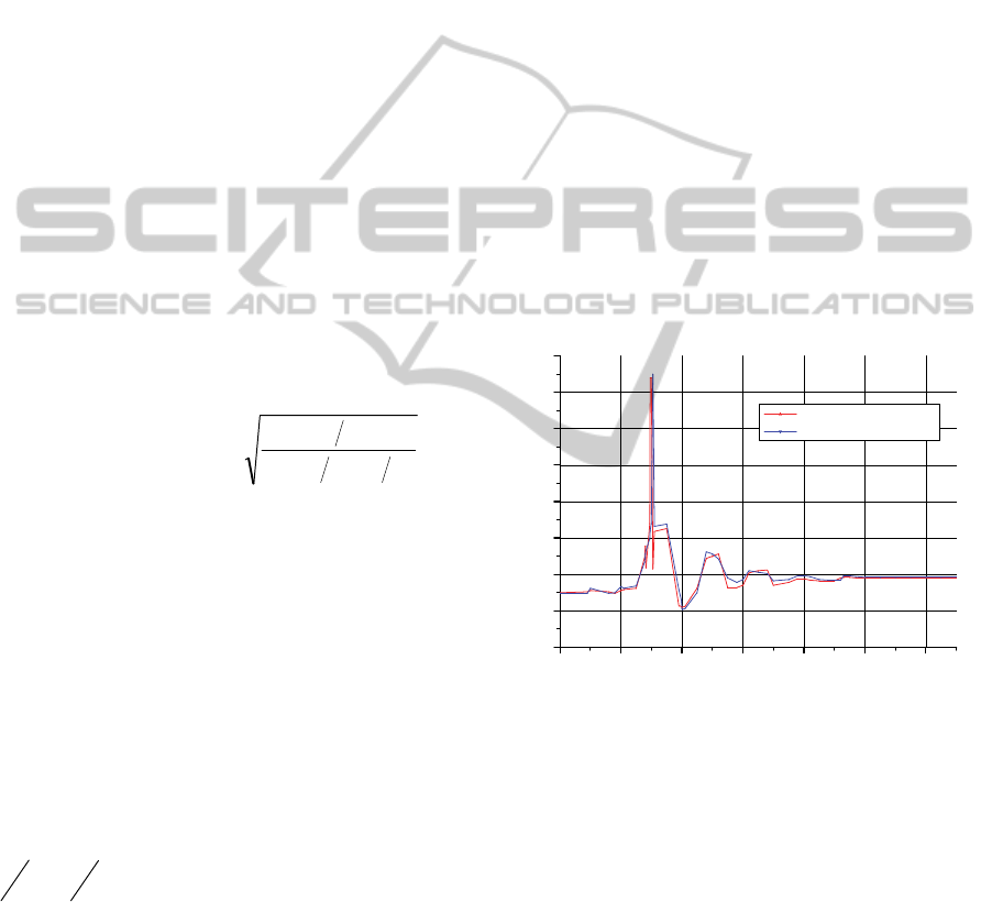
Experiment 1: According to the existing filling
process, when state transition started, the program in
the filling process is: open up 125# valve, delay of 1
second, at the same time close 124# and 134# valve,
the pump speed is 50Hz, the opening of electric
control valve DT4 is 30%. The simulation calculation
results and the real experimental results are shown in
Fig.2.
024681012
-0.5
0.0
0.5
1.0
1.5
2.0
2.5
3.0
3.5
Pressure (MPa)
Time (s)
real experiment
simulation calculation
Figure 2: Pressure change law when water hammer occurs
in the existing process.
Fig.2 shows the pressure change law when water
hammer occurs in the existing process. The abscissa
expresses the test time, the ordinate expresses the
pressure. The read curve expresses the real
experimental data of pressure, and the blue curve
expresses the simulation calculation data of pressure.
As is shown in the Fig, the pressure is 0.5MPa before
water hammer occurs. When water hammer occurs,
the pressure increases rapidly and the water hammer
peak pressure can achieve 3.25MPa. The pipeline
internal pressure has changed dramatically when
water hammer occurs, and the biggest gap can be up
to 13.5 times.
SIMULTECH2015-5thInternationalConferenceonSimulationandModelingMethodologies,Technologiesand
Applications
340
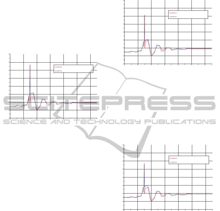
Experiment 2: On the basis of the existing filling
process, we change the closed sequential of the
related valve when water hammer occurs. When state
transition started, the existing program in the filling
process is: at the same time close 124# and 134#
valve. The changed program is: close 124# valve,
delay of 1 second, then close 134# valve. The
simulation calculation results and the real
experimental results are shown in Fig.3.
024681012
-0.5
0.0
0.5
1.0
1.5
2.0
2.5
3.0
3.5
real experiment
simulation calculation
Pressure (MPa)
Time (s)
Figure 3: Pressure change law when water hammer occurs
after changing the sequential.
The pressure change law when water hammer occurs
after changing the closed sequential of the related
valve is shown in Fig.3. In the Fig, the abscissa
expresses the test time, the ordinate expresses the
pressure. From contrasting Fig.2 and Fig.3, we can
know that it can effectively reduce the water hammer
effect of the filling pipeline by changing the closed
sequential of the related valve. The water hammer
peak pressure reduces from 3.25MPa to 2.85MPa,
and it is reduced by 12.3% compared with the data in
experiment 1.
Experiment 3: On the basis of the existing filling
process and experiment 2, we change the speed of the
filling pump when water hammer occurs. When state
transition started, the existing pump frequency is
50Hz. The changed pump frequency is 40Hz. The
simulation calculation results and the real
experimental results are shown in Fig.4.
Fig.4 shows the pressure change law when water
hammer occurs after changing the pump speed. As is
shown in the Fig, the abscissa expresses the test time,
the ordinate expresses the pressure. From contrasting
Fig.3 and Fig.4, we can know that it can effectively
reduce the water hammer effect of the filling pipeline
by changing the speed of the filling pump. The water
hammer peak pressure reduces from 2.85MPa to
2.57MPa, and it is reduced by 9.8% compared with
the data in experiment 2.
024681012
-0.5
0.0
0.5
1.0
1.5
2.0
2.5
3.0
3.5
real experiment
simulation calculation
Pressure (MPa)
Time (s)
Figure 4: Pressure change law when water hammer occurs
after changing the pump speed.
Experiment 4: On the basis of experiment 2 and
experiment 3, we change the opening of the electric
control valve DT4 when water hammer occurs. When
state transition started, the existing opening of the
electric control valve is 30%. The changed opening
of the electric control valve is 60%. The simulation
calculation results and the real experimental results
are shown in Fig.5.
024681012
-0.5
0.0
0.5
1.0
1.5
2.0
2.5
3.0
3.5
real experiment
simulation calculation
Pressure (MPa)
Time (s)
Figure 5: Pressure change law when water hammer occurs
after changing the opening of electric control valve.
The pressure change law when water hammer occurs
after changing the opening of electric control valve
is shown in Fig.5. In the Fig, the abscissa expresses
the test time, the ordinate expresses the pressure.
From contrasting Fig.4 and Fig.5, we can know that it
can effectively reduce the water hammer effect of the
filling pipeline by changing the opening of electric
control valve. The water hammer peak pressure
reduces from 2.57MPa to 2.35MPa, and it is reduced
by 8.6% compared with the data in experiment 3.
Fig.6 shows the comparison of water hammer
NumericalAnalysisonWaterHammerCharacteristicsofRocketPropellantFillingPipeline
341

peak pressure under different experimental
conditions. As is shown in the Fig, the water hammer
peak pressure in experiment 1 is the highest, and it
reduces in experiment 2, 3 and 4 in turn, the water
hammer peak pressure in experiment 4 is the lowest.
There is no significant different between the
simulation calculation data and real experimental
data under different experiment. The data
consistency is good.
12
0.0
0.5
1.0
1.5
2.0
2.5
3.0
3.5
Real Experiment
Pressure (MPa)
Simulation Calculation
Experiment 1
Experiment 2
Experiment 3
Experiment 4
Figure 6: Comparison of water hammer peak pressure
under different experimental conditions.
As is shown in Fig.6, contrasting experiment 2 and
experiment 1, the water hammer peak pressure
reduces from 3.25MPa to 2.85Mpa, and it is reduced
by 12.3% compared with the data in experiment 1.
Contrasting experiment 3 and experiment 1, the water
hammer peak pressure reduces from 3.25MPa to
2.57Mpa, and it is reduced by 20.9% compared with
the data in experiment 1. Contrasting experiment 4
and experiment 1, the water hammer peak pressure
reduces from 3.25MPa to 2.35Mpa, and it is reduced
by 27.7% compared with the data in experiment 1.
From the experimental results we can know that it
can effectively reduce the water hammer effect of
the filling pipeline by adopting the schemes
proposed in this paper.
Through data analysis for the simulation
calculation data and real experimental data, it
provides theoretical basis and data support for
reducing water hammer effect of the filling system
and optimizing filling process.
5 CONCLUSIONS
The rocket filling system is an important part of the
spaceflight launch site, the filling pipeline is one of
the key components in the filling system. Accurately
grasp it’s work state in the rocket propellant filling
process is very important for the filling accuracy and
the security and reliability of the system.
This paper analyzes the water hammer effect of
the rocket propellant filling pipeline during the
filling process of the spaceflight launch site, and
studies the influence of filling process on water
hammer. It researches the pressure change law of
filling pipeline when water hammer occurs. In order
to reduce the water hammer effect of the filling
pipeline, improved scheme in the aspects of filling
control process is put forward as follows: change the
closed sequential of the related valve, reduce the
speed of the filling pump, and augment the opening
of the electric control valve. Meanwhile, simulation
calculation and real experiment are carried through
in allusion to the proposed scheme, and carries
through data analysis for the simulation and
experimental results. The experimental results show
that the proposed scheme can effectively reduce the
water hammer effect of the pipeline during the filling
process, reduce the error of filling quantity caused by
water hammer, improve the rocket propellant filling
accuracy and enhance the security and reliability of
the system.
The water hammer effect of the rocket propellant
filling pipeline during the filling process is analyzed
in this paper only in the aspects of filling control
process. In order to further eliminate the water
hammer effect, the research direction in the future is
to improve process design for the filling system.
REFERENCES
Xiang Youhuan, Shi Jinfeng, Li Liqun. Accuracy Analysis
on Measuring Model of Rocket Propellant Filling
Based on Weight Measurement[C]. 2014 IEEE
International Conference on Signal Processing
Communications and Computing (ICSPCC 2014).
August 5-8,2014:760-765.
Yang Zhi-qiang, Zhang Hong-jian, Huang Yong-mei.
Research on data value simulation of fluid field
characteristic of vortex flowmeter [J]. Process
Automation Instrumentation. 2004, 25(5):10-13.
Yan Zheng, Peng Xiao-hui, Cheng Yu-qiang, Wu Jian-jun.
Research of water hammer and its suppression
methods for spacecraft propulsion system. Journal of
Aerospace Power. Sep.2012, Vol.27 No.9:2028-2034.
Lin Jingsong, Wang Pingyang, Gao hong. Numerical
Simulation of Water Hammer in Shutting Liquid
Rocket Engine [J]. Aerospace Shanghai. No.3
2008:53-57.
Nie Wansheng, Dai Haide, Xia Peng. Transient
Characteristics during shutdown operation of liquid
feed line for attitude control propulsion system [J].
SIMULTECH2015-5thInternationalConferenceonSimulationandModelingMethodologies,Technologiesand
Applications
342

Journal of Propulsion Technology. 2003, 24(1):6-8.
Liu Zhaozhi, Ding Pengfei, Tian Qingya. Numerical
Analysis on Water-hammer of Liquid Hydrogen
Loading System [J]. Missiles and Space Vehicles. No.4
2010, Sum No.408:10-12.
Lin Jing-song. Numerical Simulation of Water Hammer in
Shutting Liquid Rocket Engine [D]. Shanghai Jiaotong
University. 2007.
Liu Deyou, Suo Lisheng. Rigid Model of Transient
Analysis for Multiple-characteristic Long Pipeline
with Trapped Air Mass [J]. Journal of Hydrodynamics.
Ser. A, Vol.20, No.1 Jan, 2005:44-49.
Wu yuebin, Gao Jinliang. An Approach to Performance
Assessment for Water Distribution Systems.
Conference on Water Resouces Planning and
Management, Roanoke, VA, 2002.
Xu Feng, Liu Ying-yuan, Chen Hai-feng. Numerical
simulation analysis of water-hammer pressure of
rocket engine. Journal of Rocket Propulsion.
Feb.2012, Vol.38, No.1:72-75.
NumericalAnalysisonWaterHammerCharacteristicsofRocketPropellantFillingPipeline
343
