
Filling Accuracy Analysis of the Rocket Propellant
based on the Flowmeter Measuring Model
Xiang Youhuan, Zhang Ping, Liu Weidong and Cui Benting
Technical Department, Taiyuan Satellite Launch Center, Taiyuan, China
Keywords: Propellant Filling System, Flowmeter Measuring Model, Filling Accuracy, Valve-closed Delay.
Abstract: The high filling accuracy of rocket propellant is an important guarantee for the success of the rocket launch.
In view of the factors that affect filling accuracy of the rocket propellant in the filling system of the
spaceflight launch site, the algorithm of propellant filling accuracy calculation based on the flowmeter
measuring model is proposed in this paper. It respectively carries through mathematical analyses for the
different factors affecting the filling accuracy. Through the proposed algorithm, numerical calculation has
been carried on the comprehensive filling accuracy of rocket propellant under the existing filling process. It
can provide theoretical basis and data support for optimizing filling control process and improving filling
accuracy in the launch site, so as to further improving the success rate of rocket launch.
1 INTRODUCTION
The rockets propellant filling system is an important
part of the spaceflight launch site. It mainly fulfills
the task of the rocket propellant filling. High filling
accuracy of rocket propellant is an important
guarantee for the success of the rocket launch, so the
precision is a basic requirement for the filling
system (Deng, 2012). Therefore researching filling
accuracy of the rocket propellant is of great
significance to ensure complete success of the rocket
launch.
The basic filling quantity of rocket propellant is
measured by the level gauge of rocket tank, and the
quantitative-filling quantity is measured by the
flowmeter in the filling storeroom. It starts
quantitative-filling filling when reaching the
specified level. The valve automatically closes when
the flowmeter measures to the quantitative-filling
quantity. The existing filling system adopts the
filling model of volume-level, which measures the
filling quantity by flowmeter, to meet the needs of
filling quantity (Zhuang, 2005).
There are some factors that affect the filling
accuracy of rocket propellant in the propellant filling
system of the spaceflight launch site. It could
increase the risk of rocket filling and launch.
Therefore, filling accuracy of the existing filling
system in the launch site needs to be analyzed. The
factors that influence the filling accuracy need to be
improved, to improve the accuracy of the rocket
filling quantity, so as to improve the safety and
reliability of rocket filling and launch.
The rest section of the paper is organized as
follows: Section 2 introduces the related work on
filling accuracy of rocket propellant. Section 3
introduces the proposed algorithm, which is the
algorithm of filling accuracy based on flowmeter
measuring model. Section 4 analyzes the actual
filling accuracy of rocket propellant. Finally, section
5 makes conclusion.
2 RELATED WORK
At present, there are few special researches on actual
filling accuracy of propellant filling system.
However, the researches on the some factors that
affect the accuracy of propellant filling have been
carried out.
The filling measuring model based on weight
measurement is proposed in literature (Xiang, 2014).
It designs and analyzes the filling measuring model,
and analyzes the filling accuracy based on the
proposed model. It also compares the filling accuracy
with the existing volume-level measuring model, and
improves the filling accuracy. However, there are
some problems in the proposed model as follows:
First, it does not consider the system error that
caused by other equipment when calculating the
181
Youhuan X., Ping Z., Weidong L. and Benting C..
Filling Accuracy Analysis of the Rocket Propellant based on the Flowmeter Measuring Model.
DOI: 10.5220/0005505801810187
In Proceedings of the 12th International Conference on Informatics in Control, Automation and Robotics (ICINCO-2015), pages 181-187
ISBN: 978-989-758-123-6
Copyright
c
2015 SCITEPRESS (Science and Technology Publications, Lda.)

filling accuracy. For the literature, the filling
accuracy affected by the equipment can be ignored
when carries through comparison between the two
models, because the measuring error caused by these
equipments are consistent. Actually, equipment
performance can cause certain error value of filling
quantity. Second, when calculating the filling
accuracy, whether or not taking the volumetric
measurement err
or (Ma, 2013) into account. For the
literature, it needs to compare the filling accuracy
based on the existing model with the filling accuracy
based on the proposed model, and the weight
measurement model eliminates the effect of the
volumetric measurement error. So it must take the
volumetric measurement error into account when
calculating the filling accuracy. When analyzing the
filling accuracy of propellant filling system, it does
not need to consider the effect affected by
volumetric measurement error, if we take the filling
quantity given by the rocket department as reference.
In order to exactly calculate actual filling
accuracy of the rocket propellant in the spaceflight
launch site, the algorithm of propellant filling
accuracy calculation based on the flowmeter
measuring model is proposed in this paper. It takes
the factors that affect filling accuracy of the rocket
propellant into account. The factors include
flowmeter measuring, valve-closed delay,
maintenance of flowmeter set-zero and leakage of
pipeline. It respectively carries through numerical
analyses and mathematical calculation for the
different factors affecting the filling accuracy.
Through the proposed algorithm, the actual filling
accuracy of the existing rocket propellant filling
system has been figured out. It can provide
theoretical basis and data support for optimizing
propellant filling control process and improving
filling accuracy in the launch site. The following
analyses the factors that affect the filling accuracy.
The first is flowmeter measuring. The filling
quantity is measured by vortex-flowmeter in the
filling system. (Yang, 2004) The vortex-flowmeter is
a kind of new type speed instrument on the basis of
the principle of fluid oscillation. Its output signal is
pulse frequency signal or standards current signal
that is proportional to the flow, and can be
long-distance transmission. The output signal is only
related with the flux, not affected by temperature,
pressure, composition, viscosity and density of the
liquid. The measuring accuracy of vortex-flowmeter
is only 1%, the measuring accuracy is not high, and
can lead to higher error.
The second is valve-closed delay. The valves
used in the filling system are high pressure
pneumatic ball valve. Its working principle is that
opens or closes the flow path of the propellant under
the pneumatic pressure. When the rocket propellant
filling finished, in view of the time when the valve
closed, the filling automatic control process is
designed as follow. When the filling finished and the
PLC received the end signal, the filling-valve and
overflow-valve are closed at the same time.
Meanwhile, the relevant valves on the filling
pipeline are closed. When flowmeter measures to the
filling quantity, PLC sends out the instruction of
close-valve. It has a certain time delay from PLC
instruction issued to the valve fully closed, the
valve-closed delay could cause error of propellant
filling.
The third is maintenance of flowmeter set-zero.
Filling control system adopts PLC control model.
Take the second-level quantitative-filling (Yan, 2004)
for example, when PLC receives the second-level
signal, firstly the secondary instrument of the
flowmeter is set zero, and the set-zero operation
cannot be instantly restore, which need to keep 0.5
seconds, to ensure that the secondary instrument
performs normal set-zero action. The maintenance of
flowmeter set-zero could cause error of the
propellant filling.
The fourth is leakage of pipeline. The pipeline of
filling system in the spaceflight launch site is longer.
In the process of propellant filling, it’s hard to avoid
leakage of pipeline, including the outer leakage and
the inner leakage. The leakage of pipeline could
cause certain error of the propellant filling.
3 ALGORITHM OF FILLING
ACCURACY BASED ON
FLOWMETER MEASURING
MODEL
Through analysis on the factors that affects the
filling accuracy, the specific error value of filling
quantity caused by each factor has been calculated,
including the error value caused by flowmeter
measuring, the error value caused by valve-closed
delay, the error value caused by maintenance of
flowmeter set-zero and the error valve caused by
leakage of pipeline, etc. Then the actual filling
accuracy of rocket propellant can be calculated.
When carrying through numerical calculation, the
filling quantity given by the rocket department is
taken as the reference, taking no account of the
influence of
volumetric measurement error. The
specific analysis is as follow.
ICINCO2015-12thInternationalConferenceonInformaticsinControl,AutomationandRobotics
182
3.1 Numerical Analysis of Error
Caused by Flowmeter Measuring
The existing filling system adopts the filling model
of volume-level. Namely, it measures filling quantity
by flowmeter, meanwhile adopts the liquid-level
quantitative-filling way. Flowmeter start measure
from zero when it receives the liquid-level signal,
until flowmeter counts to the certain value. General
the second liquid-level is taken as the liquid-level of
quantitative-filling. Therefore, the measuring value
of the flowmeter before the quantitative-filling
liquid-level does not affect the actual filling
accuracy, only affects actual effect of display.
Actually, the error value of flowmeter measuring
equals the error value of quantitative-filling
measuring. The value could be calculated according
to the metering accuracy of flowmeter, namely 1%.
Define: the error value caused by flowmeter
measuring is E
1
(L), the quantitative-filling quantity
is b (L), the measuring accuracy of flowmeter is m.
The calculation formula of error value caused by
flowmeter measuring is as follow:
mbE ×=
1
(1)
Specific calculation data are shown in table 1.
Table 1: Error value caused by flowmeter measuring.
Rocket
level
Quantitative-filling
quantity
Theoretical value (L)
Flowmeter
accuracy
Error value
(L)
R1 2560 1% 25.6
R2 1190 1% 11.9
R3 1130 1% 11.3
Y1 1390 1% 13.9
Y2 1160 1% 11.9
Y3 1230 1% 12.3
3.2 Numerical Analysis of Error
Caused by Valve-Closed Delay
3.2.1 Mathematical Analysis
The high pressure pneumatic valve of filling system
conforms to the quick-opening flow characteristic
when valve closes. Valves provided with the flow
characteristic have larger flow when the opening is
smaller. With the increase of the opening, the flow
increases rapidly and is close to the largest soon.
Keep on adding the opening, the change of flow is
small. Therefore it is called quick-opening flow
characteristic (Pan, 2011). The function relationship
between the relative flow and f relative excursion
is:
dlKqdq
1−
= . Generating into the boundary
conditions, we can obtain the function relationship
of quick-opening flow characteristics, the formula is
as follow:
()
()
lR
R
L
L
R
RQ
Q
q
⋅−+=
⋅−+==
11
1
11
1
2
max
2
max
(2)
In the above formula, R is the ratio that valve can
control between maximum flow and minimum flow,
namely the adjustable ratio. Q is the flow that passes
through the valve. Qmax is the maximum value of
flow that passes through the valve.
max
Q
Q
is the
relative flow.
max
L
L
is the relative excursion.
For the valve of quick-opening flow
characteristic, the gain K is proportional to the
reciprocal of flow Q, or
Q
K
1
∝
. With the
increase of flow, the gain decreases.
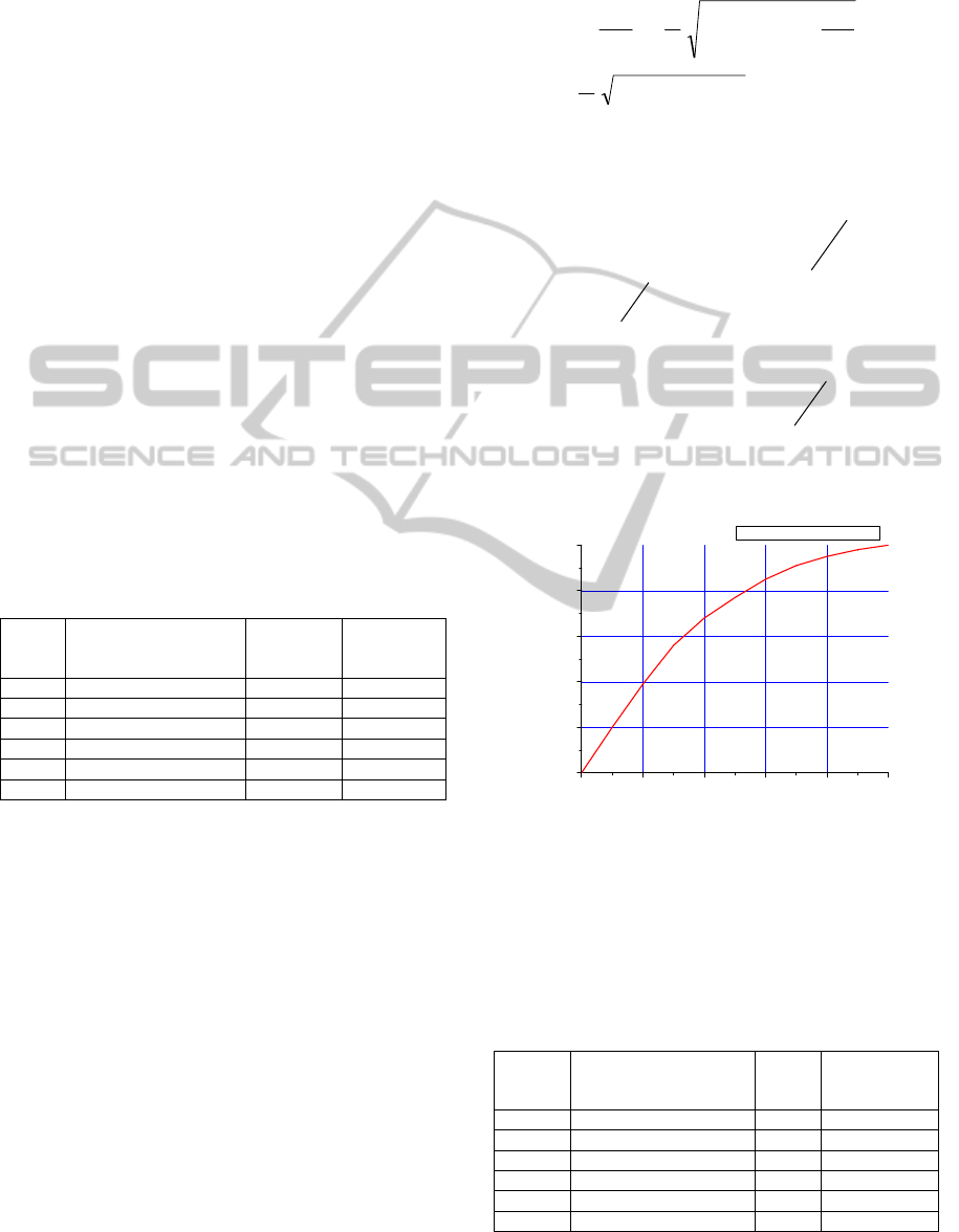
The flow characteristic curve when valve closes
is as follow:
0 20406080100
0
20
40
60
80
100
percentage of maximum flow (%)
percentage of maximum opening (%)
— flow characteristic curve
Figure 1: Flow characteristic curve when valve closes.
3.2.2 Numerical Calculation of the Error
From experiment we can get the time delay is 1.5s,
the transmission speed of electrical signal is quite
fast, and it can be ignored.
Table 2: Error value caused by valve-closed delay.
Rocket
level
Flow velocity
when filling finished
(L/min)
Time
(s)
Error value
(L)
R1 300 1.5 5.6
R2 300 1.5 5.6
R3 150 1.5 2.8
Y1 300 1.5 5.6
Y2 300 1.5 5.6
Y3 150 1.5 2.8
FillingAccuracyAnalysisoftheRocketPropellantbasedontheFlowmeterMeasuringModel
183
Define: the error value caused by valve-closed delay
is E
2
(L). Then the error value can be calculated
through the above formula. The specific calculation
data are shown in table 2.
3.3 Numerical Analysis of Error
Caused by Maintenance of
Flowmeter Set-zero
Filling control system adopts PLC to control. Take
the second-level quantitative-filling for example,
when PLC receives the second-level signal, the
secondary instrument of flowmeter is set zero. The
set-zero operation cannot be instantly restore, it need
to keep 0.5 seconds, to ensure that the secondary
instrument perform the set-zero action. The
maintenance of flowmeter set-zero could cause the
error of propellant filling quantity.
Define: The error value caused by maintenance
of flowmeter set-zero is E
3
(L). The flow velocity
when receives the second liquid-level signal is v
3
(L/min). The time of valve-closed delay is t
3
(s).
Then the error calculation formula caused by
maintenance of flowmeter set-zero is as follow:
333
tvE ×= (3)
Specific calculation data are shown in table 3.
Table 3: Error value caused by maintenance of flowmeter
set-zero.
Rocket
level
Flow velocity
(L/min)
Time
(s)
Error value
(L)
R1 300 0.5 2.5
R2 300 0.5 2.5
R3 150 0.5 1.25
Y1 300 0.5 2.5
Y2 300 0.5 2.5
Y3 150 0.5 1.25
3.4 Numerical Analysis of Error
Caused by Leakage of Pipeline
3.4.1 Mathematical Analysis
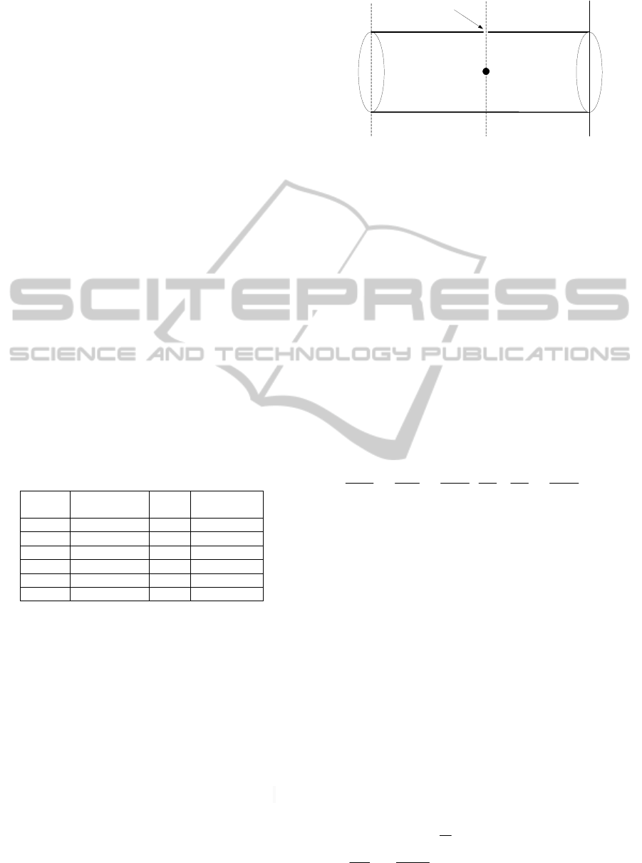
In order to calculate the error value of propellant
filling quantity caused by leakage of pipeline, the
pipeline leakage model needs to be established, as
shown in Fig.2. When the fissure of equipment is
regular, and the fissure size, physical and chemical
properties and parameters of the leakage material are
known, the leakage quantity can be calculated
according to related equations of the hydrodynamics.
When the fissure of equipment is irregular, the
fissure size can be instead of equivalent size. (Ma,
2008)
P
0
,T
0
,u
0
,ρ
0
P,T,u,ρ
Leakage
hole
Pipeline
external
N
2
Pipeline
internal
Figure 2: Leakage model of the filling pipeline.
Fig.2 shows the gas leakage process of filling
pipeline. The gas inner pipeline is nitrogen, and
there is a small leakage hole somewhere on the
pipeline. As is shown in Fig.2, the parameter (P, T, u,
ρ) respectively express the pressure, temperature,
leakage velocity and gas density nearby the leakage
hole which on the pipeline internal. The parameter
(P
0
, T
0
, u
0
, ρ
0
) respectively express the pressure,
temperature, leakage velocity and gas density nearby
the leakage hole which on the pipeline external.
In the process of the filling pipeline gas tightness
check, gas flow process can be taken as reversible
and adiabatic process of ideal gas. It follows the
state equation and Poisson equation of ideal gas. The
following equation can be obtained through the
energy conservation equation and momentum
conservation equation
0
4
ln
1
1
2
1
2
2
2
2
12
21
=+
−+
+
D
fL
T
P
T
P
RG
M
TP
TP
k
k
e
(4)
In the above formula, D is diameter of the
pipeline (mm). K is the specific heat capacity. f is
the friction coefficient. u is the gas leakage rate
(m/s). G is the gas flow (m
3
/s). R is the gas constant.
In the pore model, in view of the aperture is
smaller, pressure is not affected by gas leakage, and
the gas expansion process is isentropic. Therefore
gas leakage rate is constant, and is equal to the initial
maximum leakage rate (Dong, 2002).
a) The gas leakage calculation
The leakage rate that gas leak from the fissure is
related to its flow state (Zou, 2010). Therefore, it
needs to determine the gas flow belongs to sonic
flow or subsonic flow when calculating the leakage.
The former is called the critical flow, the latter is
called the subcritical flow (Beirami, 2006), (Boonen,
2009).
In allusion to the filling pipeline gas tightness
check, from numerical calculation we can
get:
1
1
2
0
−
+
<
k
k
kp
p
. Therefore, the gas leakage of
ICINCO2015-12thInternationalConferenceonInformaticsinControl,AutomationandRobotics
184

filling pipeline belongs to the sonic flow. In the
formula, p is the medium pressure within the
pipeline (Pa).
0
p
is the environmental pressure
(Pa). k is the gas adiabatic index, that is, the ratio
between Cp and Cv.
When the gas flow is the sonic flow, the leakage
is:
1
1
1
2
−
+
+
=
k
k
kRT
Mk
ApCQ
dg
(5)
In the above formula,
d
C is the gas leakage
coefficient, if the fissure shape was
round,
00.1=
d
C , if the fissure shape is triangle,
95.0=
d
C , if the fissure shape is rectangle,
90.0=
d
C . M is the molecular weight. p is the
medium pressure (Pa). R is the gas constant (J/(mod
• K)). T is the gas temperature (K).
If considering the leakage rate that affected by
the gas decrease or pressure reduce inside the
pipeline, the calculation of leakage rate is too
complex (Cazauran, 2009), (Zhang, 2010). In
process of the filling pipeline gas tightness check, in
view of pressure of pipeline internal is higher, and
the leakage is very small, so assume that the gas
pressure inner the pipeline is invariable when carries
through calculation.
b) Liquid leakage calculation
The liquid leakage rate can be calculated by
Bernoulli equation of hydromechanics (
Ben-Mansour,
2010), the leakage rate is as follow:
gh
pp
ACQ
d
2
)(2
0
0
+
−
=
ρ
ρ
(6)
In the above formula,
0
Q
is the liquid leakage
rate (kg/s).
d
C is the liquid leakage coefficient. A is
the area of fissure (m
2
). ρis the density of the
liquid leakage (kg/m
3
). p is the gas pressure inner
the pipeline (Pa).
0
p
is the environmental pressure
(Pa). g is the acceleration of gravity (9.8 m/s
2
). h is
the liquid-level height above the fissure (m).
3.4.2 Numerical Calculation of the Error
From the above analysis we can know the specific
calculation process, it is as follow. First of all, we
calculate the equivalent fissure size according to the
pressure drop values and gas leakage formula.5 in
the process of gas tightness check. The actual
pressure drop value is within 1%, so the value of 1%
is used in the calculation. Then we calculate the
liquid leakage rate according to the liquid leakage
formula.6. Finally we calculate the error value of
propellant filling according to the actual
quantitative-filling time.
Define: the error value of filling quantity caused
by leakage of pipeline is E
4
(L). The liquid leakage
rate is
0
Q
. The quantitative-filling time is t
4
(s). The
quantitative-filling velocity is v
4
. The
quantitative-filling quantity is b. Assuming that the
liquid leakage rate is constant in the process of
quantitative-filling. According to the real
experimental data, gas pressure drop within 1% in
half an hour in the process of gas tightness check.
The quantitative-filling time can be calculated
through the quantitative-filling quantity and the
quantitative-filling time velocity. The error value
caused by leakage of pipeline before the
quantitative-filling liquid-level does not affect the
actual filling accuracy, only affects the actual display
effect. Calculation formula is as follows:
4
0404
v
b
QtQE ×=×=
(7)
Specific calculation data are shown in table 4.
Table 4: Error value caused by leakage of pipeline.
Rocket
level
Quantitative-filling
quantity
Theoretical value (L)
Time
(s)
Error value
(L)
R1 2560 512 3.20
R2 1190 238 1.49
R3 1130 452 1.41
Y1 1390 278 1.73
Y2 1160 232 1.45
Y3 1230 492 1.54
4 NUMERICAL ANALYSIS OF
THE ACTUAL FILLING
ACCURACY
From the above numerical calculation and analysis
we can know, the infection of different factors to the
actual filling accuracy is different, and it is positive
or negative that the infection effect of different
factors to the error value of filling quantity.
Define: Fac1 expresses the error caused by
flowmeter measuring. Fac2 expresses the error
caused by valve-closed delay. Fac3 expresses the
error caused by maintenance of flowmeter set-zero.
Fac4 expresses the error caused by leakage of
pipeline. Then, the influence factor of Fac1 is “±”,
FillingAccuracyAnalysisoftheRocketPropellantbasedontheFlowmeterMeasuringModel
185
the influence factor of Fac2 is “+”, the influence
factor of Fac3 is “+”, the influence factor of Fac4 is
“±”.
Define: the actual filling error of rocket
propellant is E (L). The formula can be got as
follow:
)()()(
4
0332
4321
v
b
QtvEmb
EEEEE
×±×++×±
=±++±=
(8)
The error calculation results of rocket propellant
filling under the existing filling process are shown in
table 5.
Table 5: Actual filling accuracy of rocket propellant.
Rocket
level
E1
(L)
E2
(L)
E3
(L)
E4
(L)
Total error
(L)
Filling
accuracy
R1
±25.6
+5.6 +2.5
±3.20 -20.7~33.7 -0.81%~1.32%
R2
±11.9
+5.6 +2.5
±1.49 -5.29~20.0 -0.44%~1.68%
R3
±11.3
+2.8 +1.25
±1.41 -8.66~15.35 -0.77%~1.36%
Y1
±13.9
+5.6 +2.5
±1.73 -7.53~22.0 -0.54%~1.58%
Y2
±11.9
+5.6 +2.5
±1.45 -5.25~20.0 -0.45%~1.72%
Y3
±12.3
+2.8 +1.25
±1.54 -9.79~16.35 -0.79%~1.33%
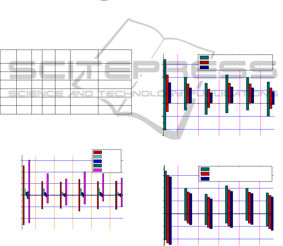
In order to more intuitive reveal the influence
that the actual filling accuracy affected by different
factors, we convert the data in the above table into
graph form, as shown in Fig.3.
123456
-20
-10
0
10
20
30
R3
R2
R1
Error value of filling quantity (L)
Rocket level
Error 1
Error 2
Error 3
Error 4
Total error
Y3
Y2
Y1
Figure 3: Filling accuracy contrast fig of the rocket
propellant.
From the data in Table5 and Fig.3, we can get
that the infection of different factors to the actual
filling accuracy is different. Fac1 has the greatest
influence on the filling accuracy, followed by Fac2,
Fac3 and Fac4 has smaller influence on the filling
accuracy.
From the above mathematical analysis and
numerical calculation, we can know that the actual
filling accuracy of rocket propellant is related with
the quantitative-filling quantity and
quantitative-filling velocity. In order to further
analyze the relationship between filling accuracy
and quantitative-filling quantity and
quantitative-filling velocity, on the one hand, the
numerical calculation of the filling accuracy is
carried through in the case of 1/2 and 1/4 of the
original quantitative-filling quantity, and the
calculated results are compared with the filling
accuracy under the original quantitative-filling
quantity. The results are shown in Fig.4. On the
other hand, the numerical calculation of the filling
accuracy is carried through in the case of 1/2 and 1/4
of the original quantitative-filling velocity, and the
calculated results are compared with the filling
accuracy under the original quantitative-filling
velocity. The results are shown in Fig.5.
-20
-10
0
10
20
30
Y3
Y2
Y1
R3
R2
R1
Error value of filling quantity (L)
Rocket level
original quantitative-filling quantity
1/2 original quantity
1/4 original quantity
Figure 4: Filling accuracy contrast fig in the case of
different quantitative-filling quantity.
123456
-20
-10
0
10
20
30
original quantitative-filling velocity
1/2 original velocity
1/4 original velocity
Y3
Y2
Y1
R3R2
R1
Error value of filling quantity (L)
Rocket level
Figure 5: Filling accuracy contrast fig in the case of
different quantitative-filling velocity.
Fig.4 shows the filling accuracy contrast in the
case of different quantitative-filling quantity, Fig.5
shows the filling accuracy contrast in the case of
different quantitative-filling velocity. As is shown in
the Fig, the actual filling accuracy of rocket
propellant is related with the quantitative-filling
quantity and quantitative-filling velocity. The
ICINCO2015-12thInternationalConferenceonInformaticsinControl,AutomationandRobotics
186

quantitative-filling quantity has much influence on
the filling accuracy, and reduce the
quantitative-filling quantity can significantly
improve the filling accuracy. The quantitative-filling
velocity has smaller influence on the filling accuracy,
but it can adjust the peak of filling error value.
Therefore reduce the quantitative-filling quantity can
reduce the maximum of filling error, so as to
improve the filling accuracy.
5 CONCLUSIONS
In terms of rocket propellant filling, this paper
analyzes the factors that affect the accuracy of the
propellant filling in the filling system of the
spaceflight launch site. It calculates the error value
of filling quantity caused by the different factors,
and carries through numerical calculation and
analysis for the actual filling accuracy of rocket
propellant. It is helpful to optimize filling model and
filling process, and provides theoretical basis and
data support for the research of improving the filling
accuracy. Through numerical analysis we can get
that the equipment performance has much influence
on the filling accuracy, in the case of definite
equipment performance, reduce the
quantitative-filling quantity and quantitative-filling
velocity can also improve the filling accuracy.
However, it does not consider the influence of
the gas-liquid two-phase flow and the propellant
temperature rise when calculating the actual filling
accuracy. The next research direction is to get the
error value of filling quantity caused by the
gas-liquid two-phase flow and the propellant
temperature rise through simulation calculation, to
perfect the factors that affect the accuracy of
propellant filling, put forward more effective
targeted measures, so as to further improve the
filling accuracy of rocket propellant.
REFERENCES
Deng Y, Qin G, Wang M, et al. Study on performance
degradation simulation and evaluation method for
pneumatic ball valve of Propellant Filling System[C].
Quality, Reliability, Risk, Maintenance, and Safety
Engineering (ICQR2MSE), 2012 International
Conference on. IEEE, 2012: 144-147.
Zhuang Ke. Design and implementation of the
conventional propellant filling factor range application
system. National University of Defense Technology,
2005.
Xiang Youhuan, Shi Jinfeng, Li Liqun, et al. Accuracy
Analysis on Measuring Model of Rocket Propellant
Filling Based on Weight Measurement[C]. IEEE
International Conference ICSPCC2014, 2014.8:
281-286.
Ma Jian, Tong Fei, Chen Zu-kui. Analysis on deviation
and measuring precision of tank volume[J]. Journal of
Rocket Propulsion. 2013 (1): 41-45.
Yang Zhi-qiang, Zhang Hong-jian, Huang Yong-mei.
Research on data value simulation of fluid field
characteristic of vortex flowmeter[J]. Process
Automation Instrumentation. 2004, 25(5):10-13.
Yan Xiao-qing, Li Zi-ran, Zhou Jin. Calculation of
bookbinding parameters and integrating method of the
software of liquid propellant utilizing system. Jourmal
of National University of Defense Technology. 2004,
26(6): 79-81.
Pan Yong-cheng, Wang Yong, Xie Yu-dong. Analysis of
Inner Flow Field Characteristics of a Control Valve
Based on CFD[J]. Machine Tool & Hydraulics. Vol.39
No.1 Jan.2011:5-7.
Ma Xiaolin, Chen Guoding. Dynamics and Leakage
Analysis of Padded Finger Seal Based on Equivalent
Model[J]. Acta Aeronautica et Astronautica Sinica.
Vol.29 No.5 Sept.2008:1356-1363.
Dong Yu-hua, Zhou Jing-en. Numerical Calculation of
Gas Leakage Rate in the Long-transport Pipeline. Oil
& Gas Storage and Transportation. Vol.21 No.8
2002:11-15.
Zou W, Yu K, Wan X. Research on the gas-leakage rate of
unsteady ventilated supercavity[J]. Journal of
Hydrodynamics, Ser. B, 2010, 22(5): 778-783.
Beirami M K, Nabavi S V, Chamani M R. Free overfall in
channels with different cross sections and sub-critical
flow[J]. Iranian Journal of Science & Technology,
Transaction B, Engineering, 2006, 30(B1).
Boonen E, Van Puyvelde P, Moldenaers P. Droplet
dynamics in sub-critical complex flows[J]. Rheologica
acta, 2009, 48(4): 359-371.
Cazauran X, Birembaut Y, Hahn R, et al. Gas Leakage
Correlation[C]//ASME 2009 Pressure Vessels and
Piping Conference. American Society of Mechanical
Engineers, 2009: 243-249.
Zhang S, Liu W, Zhang Y, et al. Gas leakage monitoring
with scanned-wavelength direct absorption
spectroscopy[J]. Chinese Optics Letters, 2010, 8(5):
443-446.
Ben-Mansour R, Habib M A, Khalifa A, et al.
Computational fluid dynamic simulation of small
leaks in water pipelines for direct leak pressure
transduction[J]. Computers & Fluids, 2012, 57:
110-123.
FillingAccuracyAnalysisoftheRocketPropellantbasedontheFlowmeterMeasuringModel
187
