
Integrating and Applying Architectural Design Patterns in Space
Flight Software Product Lines
Julie Street Fant
1,2
, Hassan Gomaa
1
and Robert G. Pettit
2
1
George Mason University, Fairfax, Virginia, U.S.A.
2
The Aerospace Corporation, Chantilly, Virginia, U.S.A.
Keywords: Software Product Lines (SPL), UML, Software Architectural Design Patterns, Unmanned Space Flight
Software.
Abstract: The unmanned space flight software (FSW) domain contains a significant amount of variability within its
required capabilities. Although all FSW execute commands from the ground station to control the
spacecraft, there is significant amount of variability in the volume of commands that must be processed, the
amount of control given to the ground station versus onboard autonomy, and the amount and type of
hardware that requires controlling. This degree of architectural variability makes it difficult to develop a
FSW software product line (SPL) architecture that covers the all possible variations. In order to address this
challenge, this paper presents a SPL approach for FSW SPLs that manages variability at a higher level of
granularity using software architectural design patterns and requires less modeling during the SPL
engineering phase. Specifically it describes how variable design patterns can be interconnected to form
FSW SPL software architectures. The design patterns are tailored to individual FSW applications during
application engineering. The paper describes in detail the application and validation of this approach.
1 INTRODUCTION
The unmanned space flight software (FSW) domain
is well-suited for applying software product line
(SPL) modeling approaches due to its commonalities
and variability. All FSW must be able to
communicate with ground stations, to execute
ground commands, and to control spacecraft
attitude. However, within each of the capabilities
there is a significant amount of variability, such as
the volume of commands that must be processed, the
amount of control that is given to the ground station
versus onboard autonomy, and the amount and type
of hardware that requires controlling. Choices made
on this variability will affect the underlying software
architectures and component interactions. This large
amount of architectural variability makes it difficult
to develop a FSW SPL architecture that covers all
possible variability. This is because typical SPL
approaches emphasize architectural variability at the
subsystem, component, and connector levels during
SPL engineering phase.
This paper addresses the needs of FSW SPL
architectures by reducing the amount of SPL
engineering modeling through the incorporation of
variable architectural design patterns and giving the
application developer the capability of customizing
the patterns to the needs of the application. Variable
design patterns contain customizable components,
connectors, and interactions rather than specific
components, connectors, and interactions. Therefore
several different combinations of specific
components, connectors, and interactions are
abstracted into one design pattern and do not need to
be individually modeled. Thus less modeling is
required during the SPL engineering phase. The
trade-off is that the application engineering phase
does require additional modeling since the
application specific components, connectors, and
interactions must be derived from the design
patterns. However, guidance is provided to help
assist the application engineer and ensure the SPL
architecture is maintained. A key piece of this
approach lies in the ability to interconnect design
patterns to form software architectures. This paper
specifically addresses how to systematically
interconnect design patterns to create a FSW SPL
software architecture.
This paper is organized as follows. After
surveying related work, it describes the overall
208
Street Fant J., Gomaa H. and G. Pettit R..
Integrating and Applying Architectural Design Patterns in Space Flight Software Product Lines.
DOI: 10.5220/0005513102080218
In Proceedings of the 10th International Conference on Software Engineering and Applications (ICSOFT-EA-2015), pages 208-218
ISBN: 978-989-758-114-4
Copyright
c
2015 SCITEPRESS (Science and Technology Publications, Lda.)

approach, including the interconnection of variable
design patterns during SPL engineering and how this
approach was applied to the FSW SPL. Then the
application engineering process is described and
illustrated using a real world case study. Next,
discuss how this FSW SPL derived applications
were validated. Finally, this paper includes a
discussion on conclusions and areas of future work.
2 RELATED WORKS
There are many notable SPL approaches including
(Clements and Northrop, 2002; Pohl et al., 2005;
Gomaa, 2005; Weiss and Lai, 1999). Many existing
SPL approaches typically focus on capturing all
possible SPL variability in the SPL engineering
phase. This becomes challenging in the FSW
domain because all possible variability in
components, connectors, and interactions must be
individually modeled. On the other hand, other
approaches focus on modeling the commonality of
the SPL and define variation points where variability
is permitted to be introduced during application
engineering (Webber and Gomaa, 2004). However,
this approach defers most development of variable
components to application engineering. The
approach described and applied in this paper takes
an intermediate approach in between modeling all
variability and limited variability by modeling SPL
variability at the architectural design pattern level.
Currently, there are very few works that discuss
building FSW from software architectural design
patterns (Herrmannn and Schöning, 2000; va
Katwijk et al., 2001; Wilmot, 2005; Wilmot, 2006).
These works describe the application a small number
of design patterns to FSW, but do not provide an
overall approach for building FSW from design
patterns.
A second set of related works describe
approaches to build real-time and embedded
software architectures from design patterns (Gomaa,
2005; Selic 2004; Douglass, 2003; Bellebia and
Douin 2006; Fliege and Geraldy 2005) and software
architectural design patterns (Gamaa et al., 1995;
Buschmann et al., 2007; Pettit and Gomaa 2006;
Kalinsky, 2002; Dupire and Gernandez, 2001).
While these approaches identify several useful
patterns for this domain, they only provide high
level guidance on their application to develop
variable software architectures. In particular, they do
not explicitly capture SPL variability in the patterns
to assist with selection of SPL members.
This paper builds on the authors’ previous work
in as follows. The PLUS method (Gomaa, 2005)
provides our overall design approach for product
lines and (Fant et al., 2013) extends this for
executable patterns. In (Fant et al., 2011), executable
design patterns were used to build FSW
architectures for single systems. This paper extends
these works by addressing variability in the FSW
domain and describing how variable design patterns
are interconnected to form SPL and SPL member
architectures. In (Fant, 2011), the concept of a
design pattern based SPL was addressed at a very
high level and did not include the specific details
about the approach. This paper extends the previous
works to describe the details of how variable design
patterns are interconnected to form SPL
architectures and relates this information to the
validation.
3 INTEGRATING DESIGN
PATTERNS DURING FSW SPL
ENGINEERING
Our approach is based on SPL design patterns, in
which variable design patterns are systematically
integrated to form SPL architectures. The main steps
include: (1) Build a set of variable distributed real-
time and embedded (DRE) architectural design
patterns that can be leveraged as a starting point, (2)
Develop a set of use cases and features that are used
to define SPL, (3) Perform use case activity
modeling to precisely capture the sequencing in use
cases, (4) Create a feature to design pattern
mapping, (5) Customize the variable DRE design
patterns to become variable SPL specific design
patterns, (6) Define the design pattern sequencing
and interconnection. The subsections below
describes each of the main steps in more detail and
describes the application to the FSW SPL’s
command and data handling (C&DH) subsystem.
3.1 Variable DRE Design Patterns
The first step in our approach is to create variable
DRE architectural and executable design patterns,
which serve as the foundation for SPLs built using
our approach. Each variable DRE architectural
pattern contains several UML views including
collaboration diagrams, interaction diagrams, and
component diagrams. Variable design patterns are
modeled at the DRE level so that they can be reused
and customized across multiple domains. Each
variable DRE design pattern is supplemented by an
IntegratingandApplyingArchitecturalDesignPatternsinSpaceFlightSoftwareProductLines
209

executable design pattern that consists of interacting
objects that execute state machines. The purpose of
the executable version of the design pattern is to
specify the internal behavior of a representative set
of the pattern’s objects and to facilitate validation of
the pattern. Each executable design pattern is
individually simulated and validated using Harel’s
approach of executable object modeling with
statecharts (Harel, 1997). We created a total 21 DRE
design patterns (Fant et al., 2011; 2013) using this
approach, including the centralized control,
distributed control, hierarchical control and layers
design patterns. The approach enables architectures
produced by interconnecting these design patterns to
be fully executable and validated, as described in
Section 5.
3.2 Use Case and Feature Modeling
Next, SPL use cases are developed applying the
PLUS method (Gomaa, 2005). This involves
identifying the use cases and variability within the
use cases through variation points, optional and
alternative use cases. From the use case variability,
an initial feature model can be developed (Gomaa,
2005). Features represent common and variable
characteristics or requirements of the SPL. Features
are analyzed and categorized as common, optional,
or alternative. Related features can be grouped into
feature groups, which constrain how features are
used by a SPL member (Gomaa, 2005).
When use case modeling was applied to the FSW
SPL C&DH subsystem, three kernel use cases with
internal variability were identified. Within these use
cases, numerous variation points were identified.
These variation points resulted in identifying 52
features. A subset of the FSW C&DH feature model
is shown in Fig. 1. This feature model contains an
<<exactly-one-of feature group>> called Command
Execution that is based on the Command Execution
use case’s Command Volume variation point. This
feature group has three <<alternative>> features.
The Low Volume Command Execution feature is
used when a small amount of commands needs
processing, the High Volume Command Execution
feature is used when a large amount of commands
needs processing, and Time Triggered Command
Execution is used when commands must be executed
with strict temporal predictability. There is also a
significant amount of variability in the amount and
type of hardware that must be commanded, which
are captured in variation points.
3.3 Use Case Activity Modeling
The next step is to create variable use case activity
models (Fant, 2011; Fant et al., 2013) Use case
activity models are activity diagrams that make the
sequencing of interactions between actor(s) and
system in a use case description more precise. In
variable use case activity diagrams (Fant, 2011),
SPL variability is captured in two ways. First,
feature based conditions are used when the flow in
activity is associated with SPL features. Feature
based conditions, such as [CommandExecution =
“LowVolume”], are modeled as branches from
decision nodes. Second, steps with variability, which
are denoted using the <<adaptable>> stereotype, can
be successively refined in separate sub-activity
diagrams. Our approach only refines adaptable steps
when they are impacted by a small number of
variation points. If an adaptable step has a
significant amount of variation points, then
modeling is deferred until application engineering
phase.
Use case activity modeling was performed on
three uses cases of the FSW SPL’s C&DH
subsystem. The FSW SPL’s Execute Commands use
case involves executing commands from the ground
station to ensure the spacecraft is not put into an
unsafe state and the actions taken are appropriate for
the spacecraft’s mode. This use case is impacted by
the Command Execution feature condition as it
influences which steps are performed. Thus the path
taken through the Execute Commands use case
activity diagram (see Fig. 2) is heavily impacted by
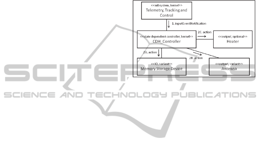
Command Execution feature condition.
As seen in Fig. 2, several variation points
including modes and spacecraft IO devices (listed in
parentheses after the step’s description) influence
the adaptable steps in the use case activity diagram.
The Spacecraft IO device variation point specifies
variations in the optional and alternative I/O devices.
These devices include antennas, antenna gimbals,
memory storage devices, power appendages, power
devices, attitude control devices, attitude
determination devices, payload devices, thrusters,
heaters, louvers, and temperature sensors. Since all
adaptable steps in this use case have significant
amount of variability as seen by the multitude of
variation points, more detailed activity modeling
was deferred to application engineering.
3.4 Feature to Design Pattern Mapping
The next step is to create a feature to design pattern
mapping. The purpose of the feature to design
ICSOFT-EA2015-10thInternationalConferenceonSoftwareEngineeringandApplications
210
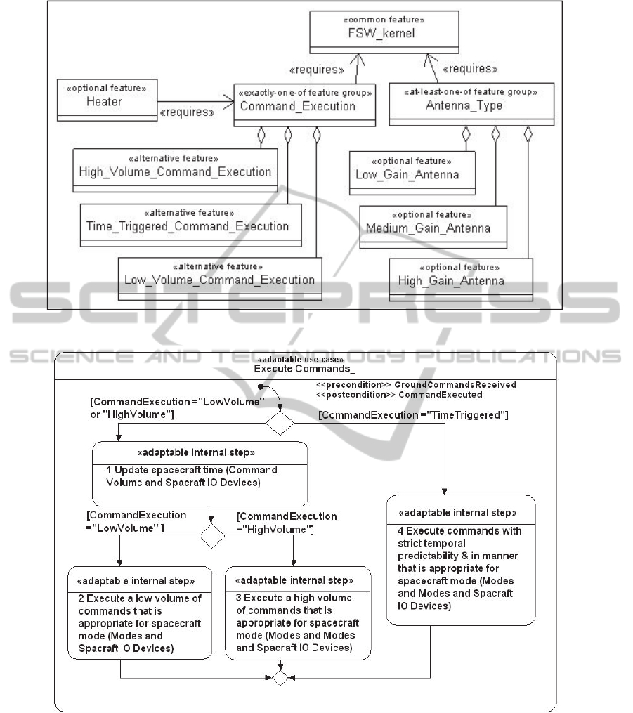
Figure 1: Subset of FSW C&DH feature model.
Figure 2: Execute Commands use case activity model.
pattern mapping is to determine which variable
design patterns could be mapped to SPL features. To
accomplish this goal, a dynamic SPL interaction
model (Gomaa, 2005) is created for each feature,
which captures the objects and object interactions
that realize each feature. Then the dynamic
interaction models are analyzed to identify where
variable design patterns can be applied in the SPL
and then relates these patterns back to the SPL
features. Features that are mapped to variable design
patterns are called pattern specific features. Pattern
specific features are coarse grained features that
relate to a design pattern and differentiate among
other related features. Pattern variability features
are fine grained features, which influence the
variability within a pattern specific feature.
IntegratingandApplyingArchitecturalDesignPatternsinSpaceFlightSoftwareProductLines
211
The feature to design pattern mapping is
demonstrated using the Low Volume Command
Execution feature. The interaction model for the
Low Volume Command Execution alternative
feature is shown in Fig. 3. Since this feature is
typically associated with small spacecraft, only the
kernel input, output, and IO devices are modeled.
The objects and interaction sequence supporting this
feature are consistent with the Centralized Control
design pattern (Fliege et al., 2005; Gamaa et al.,
1995). Thus the Low Volume Command Execution
feature is categorized as a pattern specific feature
and is mapped to the Centralized Control design
pattern.
3.5 Executable Design Patterns
The next step is to derive the variable SPL
architectural and executable design patterns from the
variable DRE architectural and executable design
patterns for each of the pattern specific features. The
purpose of the variable SPL design patterns is to add
domain specific knowledge to the design patterns so
they can be systematically incorporated into SPL
architectures. This process involves systematically
updating the components, interactions, and
component behavior to reflect the SPL specific
components and variability based on the SPL
features. While all the architectural views are
important, this paper is primarily focused on the
dynamic interaction view, since interaction diagrams
will be heavily used when interconnecting design
patterns and validating design pattern
interconnections.
First, the interaction diagrams capture the object
interactions within a design pattern. If the precise
sequence of object interactions is known, then it
should be modeled. However, in design patterns
where there is variability in the object interactions,
then only a subset of object interactions is modelled,
as shown in Fig. 3. Detailed interaction modelling,
in which other application specific I/O objects and
interactions might be added to the pattern, is
deferred to the application engineering phase. For
the FSW SPL’s C&DH subsystem, 24 interaction
diagrams were created, one for each of the pattern
specific features. As an example, Fig. 3 shows an
interaction diagram for the FSW Centralized Control
design pattern that is mapped to the specific feature.
This feature captures the FSW processing and
execution for a set of ground commands, which
involves invoking actions on the input, output, and
IO components. The type and amount of input,
output, and IO components in the FSW Centralized
Control design pattern is influenced by several
pattern variability features. For example, the
optional Heater pattern variability feature captures
whether or not the spacecraft has heaters. This
results in an optional Heater superclass component,
as seen in Fig. 3. The specific Heater subclasses are
not modeled until the application engineering phase.
Figure 3: Interaction diagram for the Low Volume
Command Execution pattern.
Secondly, state machines (Buschmann et al.,
2007) capture the internal behavior of each active
component in the design pattern. For the FSW SPL’s
C&DH subsystem, a state machine was created for
each active component in the FSW SPL’s 24
patterns. A subset of the state machine for the CDH
Centralized Controller from the Centralized Control
Design pattern is illustrated in Fig. 4. Other common
modes including launch mode and safe mode are
also modeled, but not depicted in Fig. 4. The states
comprising the modes and controlling logic are
based on the SPL pattern specific feature. The
actions within the states, which are not depicted in
Fig. 4, are determined from the pattern specific and
pattern variability features.
3.6 Design Pattern Interconnection
The next step is to capture how the variable design
patterns are integrated together to form software
architectures. A use case scenario driven approach is
used to interconnect variable design patterns to
achieve the SPL functionality. For each use case
scenario, an interaction overview diagram is created
based on the use case activity diagram. This is
accomplished by using the same control flow in the
use case activity diagrams but replacing each
activity with a reference to the variable SPL design
pattern’s interaction diagram that supports that step.
On feature based condition paths, the variable design
pattern used to achieve one or more of the steps
ICSOFT-EA2015-10thInternationalConferenceonSoftwareEngineeringandApplications
212

along the path can be determined from the feature to
design pattern mapping.
After an interaction overview diagram is created,
the design pattern interconnections are determined.
When the interaction diagrams for two design
patterns appear sequentially, they must communicate
with each other and must be interconnected.
Interaction modeling and the design pattern
integration process is illustrated using the FSW SPL
Execute Commands use case. An interaction
overview diagram is created using the same control
flow in the use case activity diagram. For instance,
since the Execute Commands use case activity
diagram (Fig. 2) begins with a feature based
decision, the Execute Commands interaction
overview diagram (Fig. 5) also begins with this same
decision point. Each of the steps in the use case
activity diagram in Fig. 2 is updated to reflect the
supporting variable design pattern’s interaction
diagram using the feature to design pattern mapping
table, as depicted in Fig. 5. For example, Step 1 on
Fig. 2 involves sending a time update. This step is
supported by the Spacecraft Clock pattern specific
feature, which is mapped to the FSW Spacecraft
Clock Multicast executable design pattern.
Therefore the FSW Spacecraft Clock Multicast’s
interaction diagram is referenced on Fig. 5. Step 2
on Fig. 2 involves executing a small number of
commands. This feature is supported by the Low
Volume Command Execution feature, which is
mapped to the FSW Centralized Control interaction
diagram, as shown in Fig. 5.
After all the FSW SPL interaction overview
diagrams were created, they were analyzed. If there
are two sequential variable design patterns, then
these design patterns must be interconnected. For
instance, in Fig. 5, the FSW Spacecraft Clock
Multicast executable design pattern interconnects
with the FSW Centralized Control and FSW
Hierarchical Control executable design patterns.
Patterns are interconnected using connectors. The
last interacting component (client or producer) of
one pattern sends a message to the receiving
component (consumer or server) of the other pattern.
The appropriate provided and required interfaces are
specified during architectural design.
4 APPLICATION ENGINEERING
After the development of the FSW SPL architecture
and components, applications are derived from
them. This is accomplished by first selecting the
appropriate FSW SPL features based on the
application’s requirements. From the feature to
design pattern mapping, the appropriate FSW SPL
executable design patterns are then determined and
customized to create the application executable
design patterns. This approach is illustrated with the
case studies described in the next section.
5 CASE STUDIES
This section describes case studies of the application
engineering process, where FSW applications are
derived from the FSW SPL assets. The process is
applied to the Student Nitric Oxide Explorer
(SNOE) and Solar TErrestrial RElations
Observatory (STEREO) application case studies,
which are real-world space programs (SNOE,, 2010;
STEREO, 2010). SNOE mission involves using a
small spin stabilized spacecraft in a low earth orbit
to measure thermospheric nitric oxide and its
variability. SNOE is a low earth orbit and relies
heavily on the ground station to control the
spacecraft’s small amount of hardware. STEREO
mission involves using two nearly identical three-
axis stabilized spacecraft orbiting around the sun to
study the nature of coronal mass ejections. Since
STEREO is not in constant communication with the
ground station, it relies on a significant amount of
autonomy and stored ground commands to control
the spacecraft. These case studies were selected
because they cover a wide variety of spacecraft in
the FSW domain.
5.1 Feature Selection
SPL pattern specific and pattern variability features
are selected based on the application’s requirements.
For SNOE’s C&DH subsystem derivation from the
FSW SPL, a total of seven pattern specific features
and seven pattern variability features were chosen.
Because SNOE is only required to process a low
volume of ground commands, the Low Volume
Command Execution alternative feature was selected
from the Command Execution pattern specific
feature group. Since this feature depends on the
Spacecraft Clock pattern specific feature, SNOE
must also select this feature.
For STEREO’s C&DH subsystem’s derivation
from the FSW SPL, a total of 10 pattern specific
features and 15 pattern variability features were
chosen. Because STEREO must store and process a
large number of commands from the ground station,
the High Volume Command Execution alternative
feature was selected from the Command Execution
IntegratingandApplyingArchitecturalDesignPatternsinSpaceFlightSoftwareProductLines
213
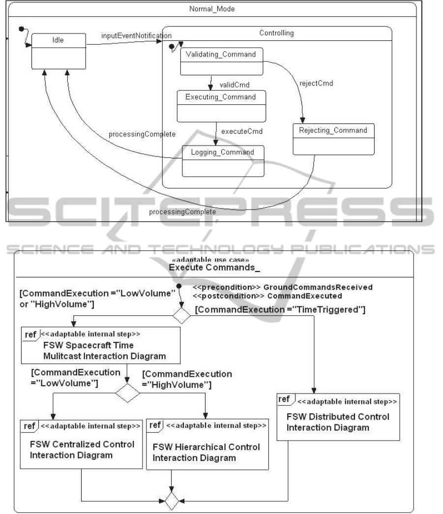
Figure 4: State machine subset for centralized controller.
Figure 5: Execute Commands interaction overview diagram.
pattern specific feature group. Some pattern
variability features are also selected. Because
STEREO is required to have onboard active thermal
control, the optional Heater pattern variability
feature is selected.
5.2 Design Pattern Customization
The next step in application engineering process is
to determine the design patterns that an application
utilizes. This information is derived from the SPL
ICSOFT-EA2015-10thInternationalConferenceonSoftwareEngineeringandApplications
214
feature to design pattern mapping and the
application’s selected features.
When this step is applied to SNOE, seven
variable design patterns were selected based on
SNOE’s seven pattern specific features. STEREO
selected a total of 10 variable design patterns based
on its pattern specific features selection. For
example, SNOE selected the FSW Centralized
Control design pattern since it is mapped to its Low
Volume Command Execution pattern specific
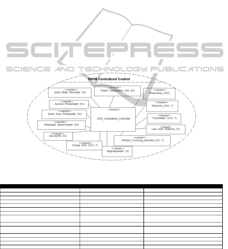
feature, as shown in Figure 6. This figure depicts the
CDH Centralized Controller connected to several
input objects and output objects, some of which are
kernel objects, while others are optional and variant
SNOE specific objects. In contrast, STEREO
selected the FSW Hierarchical Control design
pattern since it is mapped to the High Volume
Command Execution pattern specific feature.
Next, the application’s executable design
patterns are derived from the variable SPL
executable design patterns. This involves
systematically customizing the variable SPL design
pattern specification and executable pattern based on
the application’s features. As part of this process, if
an SPL design pattern’s interaction diagram only
contained a representative set of interactions, then
the interaction diagram must be updated to reflect
the precise sequence of interactions.
5.3 Design Pattern Interconnection
The application’s design pattern interconnections are
determined based on the application feature
selection. The interaction overview diagrams from
the FSW SPL’s C&DH subsystem were customized
for each application. As SNOE selected to use the
Low Volume Command Execution feature, therefore
only the feature based conditions corresponding to
this feature are selected for SNOE. This includes the
FSW Spacecraft Time Multicast interaction diagram
and the FSW Centralized Control interaction
diagram.
Figure 6: SNOE specific Centralized Control collaboration diagram.
Table 1: Subset of Design Patterns Validation.
FSW SPL Design Patterns SNOE Design Patterns STEREO Design Patterns
FSW Hierarchical Control STEREO Hierarchical Control
FSW Distributed Control
FSW Centralized Control SNOE Centralized Control
FSW Hierarchical Control with Command Dispatcher
FSW Centralized Control with Command Dispatcher
FSW Distributed Control with Command Dispatcher
FSW Telemetry Storage and Retrieval Compound Commit STEREO Telemetry Storage and Retrieval Compound Commit
FSW Telemetry Storage and Retrieval Client Server
SNOE Telemetry Storage and Retrieval Client
Server
FSW Telemetry Formation Master Slave with Pipes and Filters
FSW Telemetry Formation Master Slave with Pipes and Filters
& Strategy
FSW Telemetry Formation Pipes and Filters SNOE Telemetry Formation Pipes and Filters
FSW Telemetry Formation Pipes and Filters with Strategy STEREO Telemetry Formation Pipes and Filters with Strategy
FSW Telemetry Formation Reliability Protected Single Channel
FSW Telemetry Formation Reliability Sanity Check STEREO Telemetry Formation Reliability Sanity Check
IntegratingandApplyingArchitecturalDesignPatternsinSpaceFlightSoftwareProductLines
215
Table 2: FSW SPL Execute Commands Decision Table.
Test Specifications
«adaptable»
LV Cmd Exe.
«adaptable»
HV Cmd Exe.
«adaptable»
TT Cmd Exe.
Feature Conditions
CommandExecution = LowVolume T
CommandExecution = HighVolume T
CommandExecution = TimeTriggered T
SpacecraftClock T T F
Preconditions :Ground Commands Received
Actions
1 <<adaptable internal step>> Send spacecraft time update (Command Volume) X X
2
<<adaptable internal step>> Execute a low volume of commands that is appropriate for spacecraft mode (Modes and
Spacecraft IO Devices)
X
3
<<adaptable output step>> Execute a high volume of commands that is appropriate for spacecraft mode (Modes and
Spacecraft IO Devices)
X
4
<<adaptable output step>> Execute commands with strict temporal predictability & in manner that is appropriate for
spacecraft mode (Modes and Spacecraft IO Devices)
X
Post Conditions: Commands Executed
STEREO’s interaction overview modeling
follows the same customization process. However,
STEREO selected the High Volume Command
Execution feature, therefore only the feature-based
conditions corresponding to this feature are selected.
This includes the FSW Spacecraft Time Multicast
interaction diagram and the FSW Hierarchical
Control interaction diagram.
6 VALIDATION
The approach to validate the DRE patterns, the FSW
product line, and the SNOE and STEREO
application case studies involved several validation
steps throughout the development. First, the
individual DRE design patterns were validated by
ensuring functional correctness of the individual
executable design patterns. This was accomplished
by creating test cases to cover all states, transitions,
and actions for the state machines of all the
components in the DRE executable design pattern.
Input data to the test cases included source states and
event sequences that trigger a test case and output
data including the expected destination states and
actions.
Second, the FSW SPL individual design patterns
were also validated for functional correctness.
Again, test cases were created that covered all states,
transitions, and actions for the state machines of all
the components. Then the expected results of the test
cases were compared with the actual behavior of the
state machines. Table 1 shows a subset of the FSW
SPL design patterns that were validated using this
approach.
Thirdly, the SNOE and STEREO design patterns
were individually validated. Again, test cases were
created to cover all states, actions, and transitions for
the design patterns. However, test cases are different
from the FSW SPL test cases because they must test
all of the application customizations, including data,
logic, and additional states. Then the test cases were
compared with the actual behavior of the state
machines.
A subset of the design patterns that were
validated for SNOE and STEREO are listed in Table
1. The design patterns are listed next to the FSW
SPL design patterns they were derived from, in order
to show which SPL patterns are reused in SNOE and
STEREO. Finally, the entire SNOE and STEREO
architectures, including the design pattern
interconnections, were validated. To achieve this, a
feature based validation approach based on CADeT
(Olimpiew and Gomaa, 2009) was applied. This
approach helps to reduce the overall validation effort
by created reusable SPL test cases that can be
customized for SPL applications. The validation is
described below in more detail.
The first step was to create a decision table of
reusable test specifications for each SPL use case
activity diagram and sub-activity diagram. This step
is demonstrated using the Execute Commands’
activity diagram from Fig. 2. Each unique path
through the use case activity diagram is given a test
specification column in the decision table, as seen in
Table 2. The <<adaptable>> stereotype on the test
specifications implies it contains adaptable steps.
The feature condition rows indicate under what
feature selections this test specification applies. The
action rows indicate what steps are executed for the
test specification.
The second step is to customize the FSW SPL
test specifications for SNOE and STEREO. This is
accomplished by updating the decision tables to
include just the test specifications that are applicable
to the application. For example, in FSW SPL the
Execute Command decision table in Table 2
contains three test specifications. SNOE only uses
the Low Volume Command Execution feature, thus
adaptable test specification LV Exe. Cmd. (column 2
ICSOFT-EA2015-10thInternationalConferenceonSoftwareEngineeringandApplications
216

in Table 2) is the only applicable test specification
for SNOE. STEREO uses the High Volume
Command Execution feature, thus adaptable test
specification HV Exe. Cmd. (column 3 in Table 2) is
the only applicable test specification for STEREO.
The next step in the validation process is to refine
the adaptable steps in the test specifications to the
application. This involves refining each adaptable
test specification into non-adaptable steps based on
the application’s feature selection and populating the
steps. Steps are made into non-adaptable steps by
using the application’s specific variants, such as
replacing the Antenna superclass with the Low Gain
Antenna variant and listing the application specific
actions, such as turn on Low Gain Antenna.
Next, the test specifications input data, steps, and
output data are populated with the state, transitions,
and actions from the design pattern component state
machines. Creating this level of test specifications
detail ensures that integration testing of individual
design patterns is performed at application testing,
as well as testing interconnected design patterns.
The final step in the functional validation is to
execute the tests against the software architecture,
which consists of concurrent executable state
machines. This testing is different from validation of
the individual design patterns because it not only
tests the design patterns, but also how the design
patterns are integrated together. A total of 22
feature-based test specifications were created and
passed for SNOE and 32 feature-based test
specifications were created and passed for STEREO.
7 CONCLUSIONS
This paper has described the application of a design
pattern based SPL approach for building FSW SPL.
This approach is useful in the FSW domain because
architectural variability is captured at a larger degree
of granularity using software architectural design
patterns, thus less modeling is required during the
SPL engineering phase. The trade-off with this
approach is that additional modeling is required
during the application engineering phases. This
trade-off is acceptable in domains such as FSW,
where modeling all possible variations during the
SPL engineering phase can be time consuming and
may not always be known in advance.
Using the design pattern based approach for the
FSW SPL required significantly less component
modeling during SPL Engineering than a
component/connector based SPLE approach. In the
FSW SPL, during the SPL Engineering phase, the
design pattern based approach required modeling
only 29 components containing representative SPL
behavior, while the component/connector based
SPLE approach required 53 components containing
parameterized or specialized behavior for all the
different SPL variants. As previously discussed, the
trade-off is that additional modeling is required
during the application engineering phases. During
the application engineering of SNOE, 10 FSW SPL
components were customized to the application and
in STEREO 22 FSW SPL components were
customized.
Furthermore, this paper has described a
systematic model driven approach to determine how
design patterns are interconnected to form software
architectures. Additionally, an approach to
validating the executable software architectures at
design time is also described.
Several avenues of future investigation could be
pursued. First, this work should be extended to
address model-driven software performance
validation since meeting performance requirements
is as important as meeting functional requirements in
DRE systems. Additionally, this approach can be
applied to other distributed real-time application
domains to illustrate its applicability across other
domains. Finally, future work should address
additional automation to increase the practicality of
this work.
REFERENCES
Bellebia, D., Douin, J., 2006. “Applying patterns to build a
lightweight middleware for embedded systems,” 2006
Conference on Pattern Languages of Programs,
Portland, Oregon, USA.
Buschmann, F., Henney, K., Schmidt, D., 2007. Pattern
Oriented Software Architecture Volume 5: On Patterns
and Pattern Languages. Hoboken, NJ: John Wiley &
Sons.
Clements, P., Northrop, L., 2002. Software Product Lines:
Practices and Patterns. Addison-Wesley.
Douglass, B., 2003. Real-Time Design Patterns. Addison-
Wesley.
Dupire, B., Fernandez, E., 2001. “The Command
Dispatcher Pattern,” 8th Conference on Pattern
Languages of Programs, Monticello, Illinois, USA.
Fant, J., 2011. “Building Domain Specific Software
Architectures from Software Architectural Design
Patterns,” presented at the 33rd International
Conference on Software Engineering (ICSE) ACM
Student Research Competition (SRC) 2011, Honolulu,
Hawaii USA.
Fant, J., Gomaa, H., Pettit, R., 2011. “Architectural Design
Patterns for Flight Software,” in 2nd IEEE Workshop
IntegratingandApplyingArchitecturalDesignPatternsinSpaceFlightSoftwareProductLines
217

on Model-based Engineering for Real-Time Embedded
Systems, Newport Beach, California.
Fant, J., Gomaa, H., Pettit, R., 2013. “Modeling
Executable Architectural Design Patterns for Software
Product Lines,” Proc. 6th International Workshop on
Model Based Architecting and Construction of
Embedded Systems-ACESMB 2013, Miami, Florida,
USA.
Fliege, I., Geraldy, A., Gotzhein, R., Kuhn, T., Webel, C.,
2005. “Developing safety-critical real-time systems
with SDL design patterns and components,” Computer
Networks, vol. 49.
Gamma, E., Helm, R., Johnson, R., John, V., 1995. Design
Patterns: Elements of Reusable Object-Oriented
Software. Addison-Wesley.
Gomaa, H., 2005. Designing Software Product Lines with
UML: From Use Cases to Pattern-Based Software
Architectures, Addison-Wesley.
Gomaa, H., 2011. Software Modeling and Design: UML,
Use Cases, Architecture, and Patterns. Cambridge
University Press.
Harel, D., 1997. “Executable object modeling with
statecharts,” 18th International Conference on
Software Engineering (ICSE), Boston, MA.
Herrmann, A., Schöning, T., 2000. “Standard Telemetry
Processing – an object oriented approach using
Software Design Patterns,” Aerospace Science and
Technology, 4(4), pp. 289–297.
Kalinsky, D., 2002. “Design Patterns for High
Availability,” Embedded Systems Programming,
August.
Olimpiew, E., Gomaa, H., 2009. “Reusable Model-Based
Testing,” 11th International Conference on Software
Reuse, Falls Church, VA.
Pettit, R. Gomaa, H., 2006. “Modeling Behavioral Design
Patterns of Concurrent Objects,” Proc. ICSE 2006,
Shanghai, China.
Pohl, K., Böckle, G., van der Linden, F., 2005 Software
Product Line Engineering Foundations, Principles, and
Techniques. Springer.
Selic, B., 2004. “Architectural Patterns for Real-Time
Systems: Using UML as an Architectural Description
Language,” in UML for Real, Springer, pp. 171–188.
SNOE, 2010. Laboratory for Atmospheric and Space
Physics at the University of Colorado at Boulder,
“Student Nitric Oxide Explorer Homepage,”
http://lasp.colorado.edu/snoe/, 21-Apr-2010.
STEREO 2010. Johns Hopkins University Applied
Physics Laboratory, “STEREO Web Site,” 26-Apr-
2010. http://stereo.jhuapl.edu/index.php.
van Katwijk, J., Schwarz, J., Zalewski, J., 2001. “Practice
of Real-time Software Architectures,” IFAC
Conference on New Technologies for Computer
Control, Hong Kong.
Webber, D., Gomaa, H., 2004. “Modeling Variability in
Software Product Lines with the Variation Point
Model,” Journal of Science of Computer
Programming, 53(3), pp. 305–331.
Weiss, D., Lai, C., 1999. Software Product-Line
Engineering: A Family-Based Software Development
Process, Addison Wesley.
Wilmot, J., 2005. “A core flight software system,” 3rd
IEEE/ACM/IFIP International Conference on
Hardware/software Codesign and System Synthesis,
Jersey City, NJ, USA.
Wilmot, J., 2006. “Implications of Responsive Space on
the Flight Software Architecture,” 4th Responsive
Space Conference, Los Angles, CA.
ICSOFT-EA2015-10thInternationalConferenceonSoftwareEngineeringandApplications
218
