
Implementation of Radio Tomographic Imaging based Localisation
using a 6LoWPAN Wireless Sensor Network
Vanessa Smallbon
1
, Timothy Potie
1
, Matthew D’Souza
1
, Adam Postula
1
and Montserrat Ros
2
1
School of Information Technology and Electrical Engineering, The University of Queensland, Brisbane, Australia
2
School of Electrical, Computer and Telecommunications Engineering, University of Wollongong, Wollongong, Australia
Keywords:
Wireless Sensor Networks, Radio Tomographic Imaging, Indoor Localisation.
Abstract:
Mobile localisation has numerous uses for logistics, health, sport and social networking applications. Current
wireless localisation systems typically require the use of tracking devices to be worn or implanted. The use of
tracking devices can hinder the types applications that can be used. Wireless localisation use wireless channel
propagation characteristics, such as RF receive signal strength to localise a user’s position, which requires the
use of complex radio hardware. We developed a wireless tracking system using radio tomographic imaging
to track people without wearing a mobile tracking device. We evaluated our wireless localisation network
with users in an indoor environment. Our localisation network used the 6LoWPAN wireless communications
protocol.
1 INTRODUCTION
Tracking technology has been used for many applica-
tions, including animal migration tracking and the ad-
vancement of security systems. However, traditional
tracking methods involve visual image processing or
inaccurate heat sensor technology. Both of these ap-
proaches have strong disadvantages such as the de-
pendency on light conditions for image processing
and the fickle nature of sensitivity calibration for in-
frared sensors. Radio Tomographic Imaging (RTI)
uses inexpensive radios to track objects in a closed
area without the need for radio tags. It exploits the
ability of radio waves to travel through objects such
as trees and walls.
Current localisation techniques depend on using
sensing infrastructure already present in the environ-
ment such as visual markers, wireless LAN hotspots,
cellular networks or GPS satellite coverage. RF lo-
calisation methods such as Received Signal Strength
Indicator (RSSI) or Time of Arrival also experience
inaccuracies and reliability issues when operating in-
doors.
Current wireless localisation systems typically re-
quire the use of tracking devices to be worn or im-
planted. The use of tracking devices can hinder the
types applications that can be used. Current position
localisation use wireless channel propagation charac-
teristics, such as RF receive signal strength to localise
a user’s position, which requires the use of complex
radio hardware.
We developed a wireless tracking system that used
RSSI radio tomography to track people and objects
without using a mobile tracking device. Our wire-
less localisation system used a low powered wire-
less sensor network infrastructure which consisted of
reference nodes placed at predetermined coordinates.
The network of reference nodes continuously mea-
sure RSSI and link quality parameters. These parame-
ters are then used to form a tomographic image, show-
ing the locations of significant RF signal attenuation.
RF signals that pass through the human body or
solid inanimate objects are subjected to attenuation
RF signals and hence will affect the RSSI and link
quality between pairs of reference nodes. Locations
of RF signal attenuation are then used to determine
the position of a user or object. We developed a Ra-
dio Tomographic Localisation System (RTLS) that lo-
calises the positions of people and objects. We evalu-
ated the RTLM in a typical and realistic indoor envi-
ronment.
This article is organised into the following sec-
tions. Section 3 presents an overview of the wireless
localisation network infrastructure used. Section 4
describes the operation of the RTLM. An evaluation
of the RTLM is discussed in section 5. Conclusions
and further work are presented in section 6.
27
Smallbon V., Potie T., D’Souza M., Postula A. and Ros M..
Implementation of Radio Tomographic Imaging based Localisation using a 6LoWPAN Wireless Sensor Network.
DOI: 10.5220/0005513400270032
In Proceedings of the 12th International Conference on Wireless Information Networks and Systems (WINSYS-2015), pages 27-32
ISBN: 978-989-758-119-9
Copyright
c
2015 SCITEPRESS (Science and Technology Publications, Lda.)
2 LITERATURE REVIEW
Different types of wireless technologies have been
investigated for indoor location systems. One such
approach is the use of dead-reckoning, such as that
by Klingbeil et al (Klingbeil and Wark, 2008) who
developed an indoor localisation system using dead-
reckoning with a hip-worn mobile node that detected
a user’s footsteps and heading and used a particle fil-
tering process to estimate the position of the user.
Widyawan et al (Widyawan et al., 2008) also designed
a dead-reckoning system that used a foot-mounted in-
ertial sensor for heading and footstep detection com-
bined with a backtrack particle filtering process. Al-
though dead-reckoning can achieve a sufficient accu-
racy, the disadvantage of such systems is the require-
ment of users to wear a mobile device.
Wilson et al (Wilson and Patwari, 2010) devel-
oped an RTI system for indoor tracking, using a wire-
less sensor network. Zhao et al (Zhao et al., 2013)
used a kernel distance based estimation method for
estimating link quality for RTI. This was found to be
suitable for detecting moving people. We used a sim-
ilar approach. Qiu et al (Qiu et al., 2010) and Hu et
al (Hu et al., 2014) investigated the use of machine
learning techniques for RTI, in order to reduce inac-
curacies caused by noisy RSSI measurements.
Bonior et al (Bonior et al., 2015) developed an
RTI system implemented using software radios, in or-
der to validate the accuracy of using RSSI measure-
ments for RTI. Wang et al (Wang et al., 2015) used,
a Variational Bayesian Gaussian mixture model and
K-means clustering to improve object tracking in an
RTI system. Amendolare et al (Amendolare et al.,
2014) developed an RTI system that used both static
and mobile reference nodes for indoor environments
in first responder scenarios Martin et al (Martin, 2015;
Martin et al., 2014) presented a beam forming based
RTI model in order to improve position accuracy and
to reduce the image frame rate latency.
3 WIRELESS REFERENCE NODE
NETWORK
The wireless reference node network was based on
typical wireless sensor network infrastructure. Wire-
less sensor networks are used for a sensing and ac-
tuation applications. Wireless sensor network infras-
tructure are used for low powered indoor and outdoor
based applications and are designed to be portable and
easy to deploy, compared to other wireless LAN net-
work infrastructure. used to provide realtime received
signal strength measurements. The network consisted
of wireless reference nodes placed around the track-
ing zone. The base node was placed outside the track-
ing zone. The tinyOS 6LoWPAN based BLIP com-
munications protocol was used by the wireless refer-
ence node network.
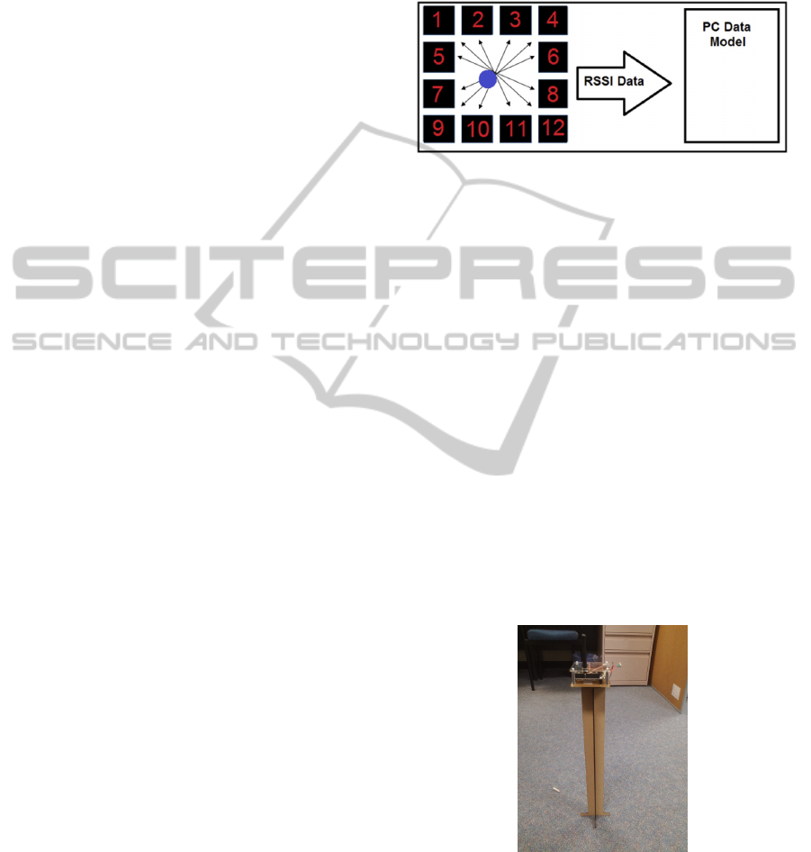
Figure 1: Overview of Wireless Reference Node Network.
The wireless reference node network as seen in
Figure 1 consisted of two types of nodes: base and
reference nodes. The reference nodes are placed
around the boundaries of the zone in which users
are tracked in. The reference nodes are used to
measure the radio received signal strength from the
base node. The server connected to the node node
displays the current position of the person. The
reference and base nodes used the Zigduino plat-
form (Logos Electromechanical LLC, 2013) with
TinyOS (TinyOS, 2013). The Zigduino uses the At-
mega128RFA1 Wireless System on Chip (SoC) that
has an Atmega128 microcontroller and a 2.4GHz Zig-
bee/802.15.4 transceiver (Atmel Corporation, 2012).
The 6LoWPAN protocol was used to provide a wire-
less communication link between the base and refer-
ence nodes.
3.1 Reference Node
Figure 2: Reference Node.
The reference node, seen in Figure 2, communi-
cates to the base node using a 6LoWPAN network
connection. The reference nodes are by the RTLM
to locate people and objects in the tracking zone. The
position of each reference node is known by the base
node. Each reference node has a predetermined ID
WINSYS2015-InternationalConferenceonWirelessInformationNetworksandSystems
28
which is included in each packet transmitted. The
reference node is powered by a rechargeable battery.
As mentioned previously, the reference node is im-
plemented using the Zigduino platform with the At-
mega128RFA1 SoC. The Atmega128RFA1 has a re-
ceiver sensitivity range of 88dB with 1dB resolution
and has a minimum signal power detection threshold
of -90dBm (Atmel Corporation, 2012). The transmis-
sion power can vary from 3.5dBm to -16.5dBm. The
reference node used a transmission power setting of
-16dBm.
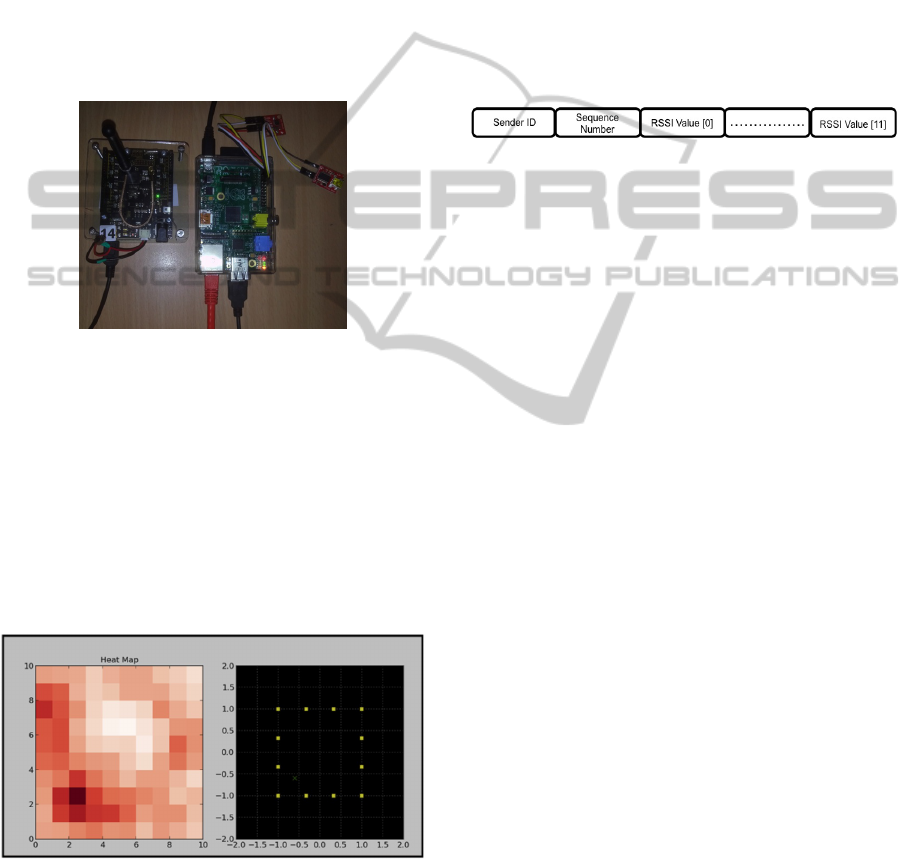
3.2 Base Node
Figure 3: Base Node.
The base node, seen in Figure 3, receives and pro-
cesses packets from each reference node. The base
node is connected by a USB connection to a server
computer. The server computer tracks the position
of the person using the RTLM. The server com-
puter used is a Raspberry Pi embedded linux plat-
form (Raspberry Pi Foundation, 2013). A graphical
user interface, written in Python was used to display
the current status of the reference nodes (transmitting
or receiving) and the heatmap. This is shown in Fig-
ure 4.
Figure 4: Graphical User Interface showing Heatmap and
Node Status.
3.3 Reference Node Protocol
The Reference Node Protocol (RNP) was developed
to provide maximum received signal strength resolu-
tion required by the RTLM. The RNP was used by
each reference node to measure the RSSI and to syn-
chronise the transmission of each reference node. The
protocol was required to minimise radio interference
and to be self regulating. RNP was implemented us-
ing 6LoWPAN with the TinyOS BLIP library. RNP
used the IP protocol User Datagram Protocol (UDP)
to transfer packets between the nodes.
The RNP packet can be seen in Figure 5, consists
of a sender ID and the RSSI values of neighbouring
reference nodes detected. RNP uses a round robin
slot scheme, in which each reference node will only
transmit, depending the reference sender node ID last
received. The RNP used a slot time period of 300ms.
Figure 5: Reference Node Protocol Packet Format.
4 RADIO TOMOGRAPHIC
LOCALISATION SYSTEM
The Radio Tomographic Localisation System (RTLS)
estimates a person’s position using RSSI attenuation
measurements. RSSI is the measured received sig-
nal strength between a transmitter/receiver reference
node link. RF signals that pass through the human
body or inanimate objects are subjected to attenua-
tion or reflection, which affects the RSSI and between
a transmitting and receiving reference node link. The
RTLM uses the network of reference nodes to con-
tinuously measure RSSI and link quality parameters.
The RTLM forms a tomographic image of RF sig-
nal strength and determines the locations of signifi-
cant RF attenuation. Locations of attenuation are then
used to determine the position of a person in the track-
ing zone.
Figure 6 shows an overview of the RTLM. The
RTLM was based on kernel distance estimation as
used by Zhao et al (Zhao et al., 2013). The RTLM
first estimates the attenuation between pairs of refer-
ence nodes using RSSI histogram filtering and link
attenuation estimation. Once the link quality between
the reference node links has been computed, a tomo-
graphic image showing the heatmap of signal attenu-
ation can be formed. Areas of significant attenuation
are then used to determine the location of objects and
users. A grid averaging is then used to reduce dis-
tortions in the tomographic image, caused by fluctua-
tions in link attenuation estimates.
ImplementationofRadioTomographicImagingbasedLocalisationusinga6LoWPANWirelessSensorNetwork
29
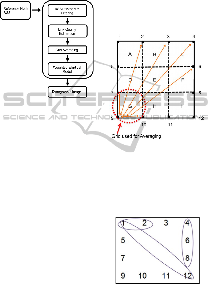
Figure 6: Radio Tomographic Localisation System
Overview.
4.1 RSSI Histogram Filtering
The RSSI readings for a link between reference nodes
is used to determine the level of attenuation between
the reference nodes. For each link, two histograms
were created to track the distribution of RSSI values.
The histogram is used to measure the occurrence of
RSSI values. For each link, a short and long time
histogram was used. The short term histogram keeps
track of the most recent RSSI values while the long
term histogram tracks the long RSSI values over a
longer period of time. The use of two histograms
is advantageous as it allows dynamically moving ob-
jects to be detected with more certainty as discussed
in (Zhao et al., 2013).
4.2 Link Attenuation Estimation
The link attenuation is used to determine if a person
or object is between the nodes. For each link, the link
attenuation is calculated using the difference between
the long and short term histograms. The difference
between the long and short term histograms is a mea-
sure of the change of attenuation that has occurred for
a particular link. The kernel distance is used to cal-
culate the difference between the long and short term
histograms. The change in attenuation is then used to
form a tomographic image.
4.3 Grid Averaging
Link attenuation can fluctuate significantly, which can
cause distortions in the tomographic image. In order
to reduce fluctuations in link attenuation, a grid aver-
aging method was used. The tracking zone is divided
into an evenly spaced grid, as shown in Figure 7. The
link attenuation estimates of each link that crosses
a particular grid are averaged and then assigned the
same averaged value.
Figure 7: Grid Averaging.
4.4 Weighted Elliptical Model and
Tomographic Image
A tomographic image of the tracking zone is formed
using the link attenuation estimates. A weighted el-
liptical model using the link attenuation estimates is
formed, as shown in Figure 8. Using the a wighted
elliptical model, an image can be formed where each
pixel is assigned a value, if it falls within the ellipse
formed by the reference nodes in the link. Each pixel
value corresponds to a heat map colour value.
Figure 8: Example of Weighted Elliptical Model using Ref-
erence Node IDs.
WINSYS2015-InternationalConferenceonWirelessInformationNetworksandSystems
30
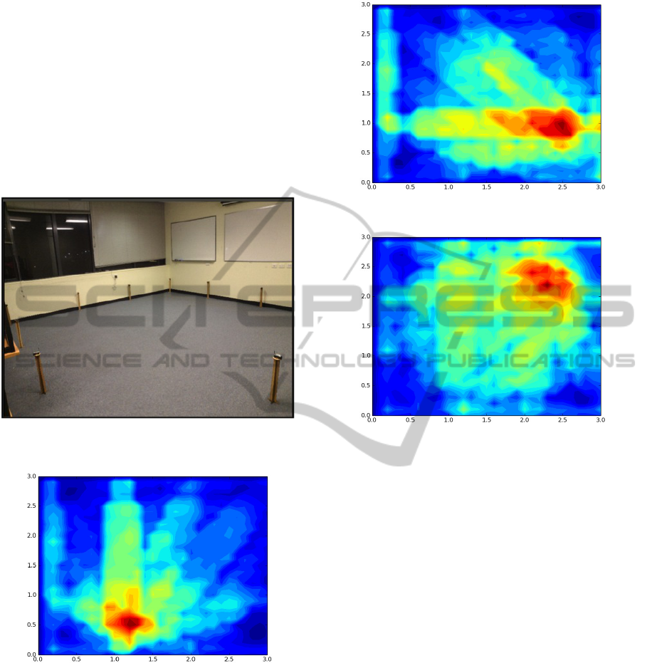
5 EVALUATION
The RTLM was tested in an indoor environment
shown in Figure 9. The reference node network was
setup in a 5m by 5m open space. We tested the RTLM
by having a person stand and walk, within the track-
ing zone. Figure 10 shows the person standing in the
middle of the lower boundary. Figure 11 shows the
person standing in the middle of the right boundary.
Figure 12 shows the person in the top right corner of
the tracking zone.
Figure 9: Reference node Localisation Network Deploy-
ment.
Figure 10: Person Standing in the Middle of the Lower
Boundary.
6 CONCLUSIONS
We presented a wireless indoor localisation system
that tracked people in an indoor environment, using
radio tomographic imaging. We developed the RTLM
which formed a tomographic image using RSSI link
quality estimation. The RTLM used a 6LoWPAN
based wireless sensor network, to measure link atten-
uation between a pair of reference nodes. The link
attenuation was then used to form a tomographic im-
Figure 11: Person Standing in the Middle of the Right
Boundary.
Figure 12: Obstacles in the upper left boundary.
age, showing the locations of significant RF signal at-
tenuation.
Locations of RF signal attenuation are then used
to determine the position of a user or object. We eval-
uated the RTLM in an realistic indoor environment.
The RTLM was able to detect people and obstacles in
the tracking zone. Further work involves, developing
a self power calibration mechanism, allow for multi-
ple people tracking and to track users in large indoor
office environments. We are also investigating the use
of a tablet interface to view the heatmap and tracking
information.
ACKNOWLEDGEMENTS
The authors would like to thank the School of ITEE
at The University of Queensland and the Pervasive
Computing Group at CSIRO for their support in this
project.
REFERENCES
Amendolare, V., Cyganski, D., and Duckworth, R. (2014).
Transactional array reconciliation tomography for
ImplementationofRadioTomographicImagingbasedLocalisationusinga6LoWPANWirelessSensorNetwork
31

precision indoor location. Aerospace and Electronic
Systems, IEEE Transactions on, 50(1):17–32.
Atmel Corporation (2012). Atmega128rfa1 datasheet.
Bonior, J., Hu, Z., Guo, T., Qiu, R., Browning, J.,
and Wicks, M. (2015). Software-defined-radio-based
wireless tomography: Experimental demonstration
and verification. Geoscience and Remote Sensing Let-
ters, IEEE, 12(1):175–179.
Hu, Z., Hou, S., Wicks, M., and Qiu, R. (2014). Wireless to-
mography in noisy environments using machine learn-
ing. Geoscience and Remote Sensing, IEEE Transac-
tions on, 52(2):956–966.
Klingbeil, L. and Wark, T. (2008). A wireless sensor
network for real-time indoor localisation and motion
monitoring. In Information Processing in Sensor Net-
works, 2008. IPSN ’08. International Conference on,
pages 39 –50.
Logos Electromechanical LLC (2013). Zigduino R2.
”http://logos-electro.com/zigduino/”.
Martin, R. (2015). Inverse beamforming for radio tomogra-
phy. Signal Processing Letters, IEEE, 22(2):187–191.
Martin, R., Folkerts, A., and Heinl, T. (2014). Accuracy
vs. resolution in radio tomography. Signal Processing,
IEEE Transactions on, 62(10):2480–2491.
Qiu, R., Hu, Z., Wicks, M., Hou, S., Li, L., and Gary, J. L.
(2010). Wireless tomography, part ii: A system engi-
neering approach. In Waveform Diversity and Design
Conference (WDD), 2010 International, pages 277–
282.
Raspberry Pi Foundation (2013). Raspberry Pi.
”http://www.raspberrypi.org/”.
TinyOS (2013). TinyOS. ”http://www.tinyos.net/”.
Wang, Q., Yigitler, H., Jantti, R., and Huang, X. (2015).
Localizing multiple objects using radio tomographic
imaging technology. Vehicular Technology, IEEE
Transactions on, PP(99):1–1.
Widyawan, Klepal, M., and Beauregard, S. (2008). A
backtracking particle filter for fusing building plans
with pdr displacement estimates. In Positioning, Nav-
igation and Communication, 2008. WPNC 2008. 5th
Workshop on, pages 207 –212.
Wilson, J. and Patwari, N. (2010). Radio tomographic imag-
ing with wireless networks. Mobile Computing, IEEE
Transactions on, 9(5):621–632.
Zhao, Y., Patwari, N., Phillips, J. M., and Venkatasubra-
manian, S. (2013). Radio tomographic imaging and
tracking of stationary and moving people via kernel
distance. In Proceedings of the 12th international
conference on Information processing in sensor net-
works, IPSN ’13, pages 229–240, New York, NY,
USA. ACM.
WINSYS2015-InternationalConferenceonWirelessInformationNetworksandSystems
32
