
A Path-based Equivalence Checking Method for Petri Net based Models
of Programs
Soumyadip Bandyopadhyay, Dipankar Sarkar, Kunal Banerjee and Chittaranjan Mandal
Indian Institute of Technology, Kharagpur, India
Keywords:
Translation Validation, Equivalence Checking, PRES+ Model, FSMD Model.
Abstract:
Programs are often subjected to significant optimizing and parallelizing transformations. It is therefore impor-
tant to model parallel behaviours and formally verify the equivalence of their functionalities. In this work, the
untimed PRES+ model (Petri net based Representation of Embedded Systems) encompassing data processing
is used to model parallel behaviours. Being value based with inherent scope of capturing parallelism, PRES+
models depict such data dependencies more directly; accordingly, they are likely to be more convenient as the
intermediate representations (IRs) of both the source and the transformed codes for translation validation than
strictly sequential variable-based IRs like Finite State Machines with Datapath (FSMDs) (which are essen-
tially sequential control data-flow graphs (CDFGs)). In this work, a path based equivalence checking method
for PRES+ models is presented.
1 INTRODUCTION
Recent advancement of multi core and multi proces-
sor systems has enabled incorporation of concurrent
applications in embedded software systems through
extensive optimizing transformations for better time
performance and resource utilization (Gupta et al.,
2003). If such optimizations are carried out by un-
trusted compilers, they can result in software bugs.
Hence, it is important to verify whether the optimized
code faithfully represents the intended functionality.
A comprehensive list of models proposed to rep-
resent programming systems and their validation can
be found in (Edwards et al., 1999; Akl, 1997; Mil-
ner, 1989). Petri nets have long been popular model-
ing paradigm for concurrent behaviours. The untimed
one safe PRES+ model (Petri net based Representa-
tion for Embedded Systems) (Cort
´
es et al., 2003) en-
hances the classical Petri net model to capture natu-
ral concurrency and well defined semantics of com-
putations over integers, reals and general data struc-
tures. Analyses of dependencies among the opera-
tions in a program lie at the core of many optimizing
and parallelizing transformations. Being value based
with inherent scope of capturing parallelism, PRES+
models depict such data dependencies more directly;
accordingly, they are likely to be more convenient
as the intermediate representations (IRs) of both the
source and the transformed codes for translation vali-
dation than strictly sequential variable-based IRs like
all types of control data-flow graphs, communicating
sequential processes, etc.
Behavioural verification involves demonstrating
the input-output equivalence of all computations rep-
resented by the original behavioural description with
those of the transformed behavioural description.
From the success of path based equivalence check-
ing of CDFG models (essentially FSMDs) recorded
in (Banerjee et al., 2014), it is perceived that a similar
approach is worth pursuing for PRES+ models. Path
structures in PRES+ models, however, are far more
complex than those in CDFG models due to the pres-
ence of parallel threads of computations in the former.
The major contributions of the present paper are as
follows:
1. A formal definition of computations of untimed
PRES+ models is provided.
2. An algorithm for path construction of PRES+
models is provided and formally treated.
3. An algorithm for path based validation of PRES+
models is provided and formally treated.
Organization: The rest of the paper is organized
as follows. Section 3 describes an overview through
a motivating example. Section 4 formally introduces
the untimed PRES+ model, its computational seman-
tics and also the notion of computational equivalence
between two PRES+ models. The concept of cut-
319
Bandyopadhyay S., Sarkar D., Banerjee K. and Mandal C..
A Path-based Equivalence Checking Method for Petri Net based Models of Programs.
DOI: 10.5220/0005513903190329
In Proceedings of the 10th International Conference on Software Engineering and Applications (ICSOFT-EA-2015), pages 319-329
ISBN: 978-989-758-114-4
Copyright
c
2015 SCITEPRESS (Science and Technology Publications, Lda.)
points and paths in a PRES+ model is introduced and
a path construction algorithm is also given in sec-
tion 5; an equivalence checking algorithm is given in
section 6. Experiments on some benchmarks can be
found in section 7. Section 8 states the related work
on translation validation. The paper is concluded in
section 9.
2 FRAMEWORK
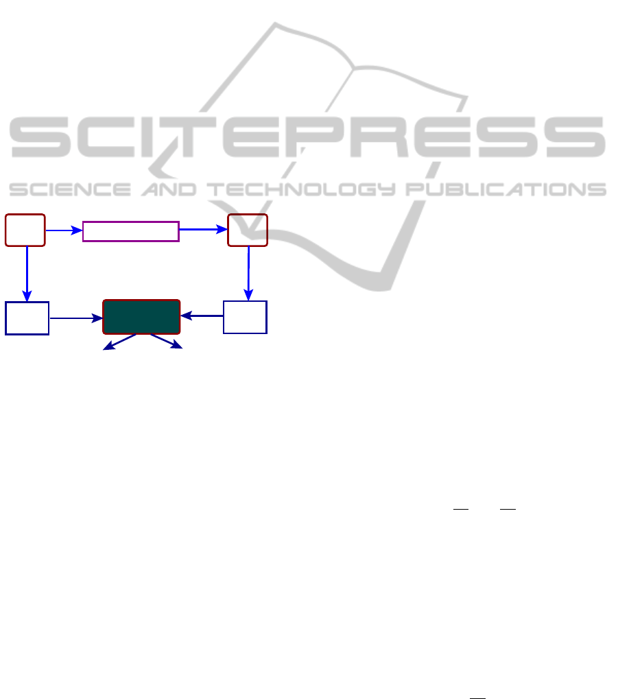
Figure 1 depicts the actual framework of the present
work. A software program is compiled using some
compiler transformation techniques and an optimized
intermediate code is produced. Validation of such
transformations is a undecidable problem. On the
other hand, if we are able to establish the computa-
tional equivalence between the original and the trans-
formed programs, we can claim that the transforma-
tions applied for the specific run is correct. Therefore,
our main target is to develop an equivalence checker
for translation validation.
Prog
Transf
Prog
Compiler
PRES+
model
PRES+
model
Equivalence
checker
yes
no
Figure 1: Basic framework.
For program analysis, it is necessary to translate
any program to its equivalent formal model represen-
tation. As the main target of this work is to validate
code optimizing and several parallelizing transforma-
tions, a parallel model of computation (MoC) is nec-
essary. In this work, the PRES+ model, whose un-
derlying structure is a one safe Petri net model with
token holding values, is selected as the parallel MoC.
Therefore, PRES+ models are constructed from both
the original and the transformed program. The au-
tomated PRES+ construction method from high level
language is reported in (Cortes et al., 2000). Here, our
main task is to devise a PRES+ equivalence checker
which takes two PRES+ models as inputs and returns
either “yes” or “no” as its output. If the equivalence
checker gives a “yes” response, then the two programs
are equivalent, i.e., particular transformations which
are carried out by the compiler are correct; if it gives
a “no” response, then the two programs may not be
equivalent. Hence, our method is sound but not com-
plete and it may give a false negative result. The ba-
sic steps of the equivalence checking procedure are as
follows: (1) In the first step, a PRES+ model is parti-
tioned into several fragments which are called paths;
the paths are obtained by cutting a loop in at least one
cut-point which is adapted from (Floyd, 1967); any
computation of the model can now be represented as
a concatenation of these paths. (2) Next, checking
whether for all paths in the PRES+ model N
0
, say,
which corresponds to the source program, there ex-
ists a path in the PRES+ model N
1
, say, which corre-
sponds to the transformed program such that the two
paths are equivalent, i.e., their data computations and
conditions of execution are identical and their input
and output places have correspondence. (3) Repeat
steps 1 and 2 with N
0
and N
1
interchanged. The ma-
jor challenges of this work are as follows:
1. Path construction procedure for a PRES+ model
2. Equivalence checking method for PRES+ models.
3 METHODOLOGY
Before describing the formal notion of path based
equivalence checking mechanism between two
PRES+ models, in this section, we underline through
an example some of the relevant issues which arise
during development of an equivalence checker for
PRES+ models.
int i = 1, j = 1;
int i = 1, j = 1;
int k;
while (i*7 <=100)
i++
;
while ((j+1)*11 <=100)
j++;
k = i+j;
int k;
while ((j+1)*11 <=100)
j++;
while (
i*7 <=100)
i++
;
k = i+j;
int i = 1, j ;
int k;
j = i;
#parbegin
while (
i*7 <=100)
i++
;
||
while (
(j+1)*11 <=100)
j++;
#parend
k = i+j;
(c)
(b)(a)
Figure 2: Initial and Transformed Behaviour.
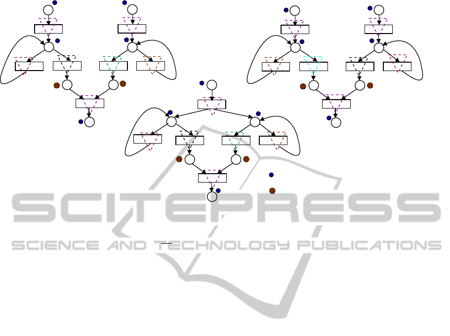
Example 1. Figure 2 (a) represents an initial pro-
gram which computes d
100
7
e + b
100
11
c. Figure 2(b)
and 2(c) pertain to programs transformed using loop
swapping transformation and thread level paralleliz-
ing transformations, respectively. Figures 3 (a), 3(b)
and 3(c) depict the PRES+ models corresponding to
the programs given in Figures 2(a), 2(b) and 2(c), re-
spectively. Automated model construction from high
level program to its equivalent PRES+ model is re-
ported in (Cortes et al., 2000).
Let us now address the issues in finding equiv-
alence between the PRES+ models of Figures 3(a)
and 3(c). In Figure 3(a), the fragments p
1
.(p
3
)
n
.p
5
computes the first term d
100
7
e and the fragment
ICSOFT-EA2015-10thInternationalConferenceonSoftwareEngineeringandApplications
320
c
1
: (v
+1)*11<=100
c
: v
2
’
’
p
p
3
’
’
*7<=100
4
4
c
1
*7<=100]
: [v
c
2
+1)*11<=100]
p
p
3
: [(v
2
c
1
:
v
p
’’
*7<=100
c
2
’’
’’
v
p
3
’’
:
(
+1)*11<=100
]
’’
1
1 1
+1 id
id +1
+
p
1
p
2
p
3
p
4
p
5
p
6
p
7
t
1
t
2
t
3
t
4
t
6
[c
1
]
[~c
1
]
[~c
2
]
[c
2
]
(a)
t
7
t
5
α
1
α
2
α
3
α
4
α
5
α
6
α
7
(b)
t
7
’
’
’
’ ’
’
’
’
’
’
’
’
’
’
’ ’
’
’
1 1
+1 id
id +1
+
p
1
p
2
p
3
p
4
p
5
p
6
p
7
t
1
t
2
t
3
t
4
t
5
t
6
[c
]
[~c
]
[~c
]
[c
]
1
2
1
2
: Dynamic cut−point
p
’’
β
3
β
4
β
6
β
1
id
id +1
+
p
p
p
p
p
t
t
]
[c
]
1
2
3
4
5
6
t
1
3
t
4
t
6
’’
’’
’’
’’
’’
’’
’’
’’
’’
’’
’’
’’
2
[~c
2
[~c
1
]
+1
β
2
1
’’
[c ]
5
’’
β
5
1
(c)
2
’’
t
: Static cut−point
Figure 3: Initial and transformed PRES+ models.
p
2
.(p
4
)
m
.p
6
computes the second term b
100
11
c; corre-
spondingly, in Figure 3(c), p
00
1
.(p
00
2
)
n
.p
00
4
computes the
first term and p
00
1
.(p
00
3
)
m
.p
00
5
computes the second term
(n 6= m). In general, in a computation, the number
of traversals of a loop in a PRES+ model depends
upon the input token values. Since equivalence has
to be established for all computations, the notion of
finite computation paths is used so that any compu-
tation can be captured in terms of these paths. To
do so, we cut the loops by introducing cut-points so
that every loop is cut in at least one cut-point; each
path will originate from a set of cut-points and ex-
tend up to a cut-point without having any intermedi-
ary cut-points. In Figure 3(a), suppose the cut-points
are p
1
, p
2
(as in-ports), p
3
, p
4
(for cutting the loops),
p
7
(for the out-port) and p
5
, p
6
(extra cut-points). A
path is represented as a sequence of maximally par-
allelizable transitions; hence the corresponding paths
are also depicted in Figure 3(a) using inverted dotted
triangular boxes, such as α
7
= h{t
7
}i and the com-
putation µ
p
7
can be represented as (α
1
k α
2
).(α
3
k
α
4
)
m
.(α
3
k α
6
).(α
3
)
n
.α
5
.α
7
. Thus, introducing extra
cut-points judiciously is an important step which will
be discussed in detail in the subsequent sections.
Similarly, in Figure 3(c), the paths are as shown
by inverted dotted triangular boxes with cut-points
{p
00
1
, p
00
2
, p
00
3
, p
00
4
, p
00
5
, p
00
6
}. Two entities are used to char-
acterize a path α: (1) the condition of execution R
α
,
and (2) the data transformation r
α
; these are com-
puted by the forward substitution method. For the
paths α
1
and α
3
in Figure 3(a), R
α
1
(v
p
1
) : “true
00
and
R
α
3
(v
p
3
) : v
p
3
∗7 ≤ 100; and the data transformations
are r
α
1
(v
p
1
) = 1 and r
α
3
(v
p
3
) = v
p
3
+ 1.
Let the in-port association f
in
⊆ inP
0
× inP
1
be
{hp
1
, p
00
1
i,hp
2
, p
00
1
i}; let out-port association f
out
:
outP
0
↔ outP
1
be p
7
7→ p
00
6
. For each path of Figure
3(a), the equivalent path of Figure 3(c) is obtained.
Specifically, we obtain α
1
' β
1
, α
2
' β
1
, α
3
' β
2
,
α
4
' β
3
, α
5
' β
4
, α
6
' β
5
and α
7
' β
6
; also, their in-
put and output places have correspondence. Since all
the paths of the original behaviour have some equiv-
alent paths in the transformed behaviour, and vice
versa, the models are asserted to be equivalent. We
can also establish the equivalence between the mod-
els of Figures 3(a) and 3(b) identically.
Path Extension: Code motion transformations
move code segments beyond the basic block bound-
aries; consequently, some paths of one model may
be found to have no equivalent paths in the other
model. Such paths will have to be extended through its
subsequent path(s) till paths equivalent to the result-
ing concatenated path(s) are obtained. The idea of
path extension is similar to that of path based FSMD
equivalence checking mechanism (Banerjee et al.,
2014). Intricacies, however, arise due to the presence
of paths parallel to the path being extended. This sit-
uation is presented in section 6 through Example 5.
4 THE PRES+ MODEL AND ITS
COMPUTATION
A PRES+ model is a 6−tuple N =
hP,T,I,O,inP,outPi, where the members are de-
APath-basedEquivalenceCheckingMethodforPetriNetbasedModelsofPrograms
321

fined as follows. P: a finite non-empty set of places.
A place p is capable of holding a token having a
value v
p
from a domain D
p
. A token value may
be of type Boolean, integer, etc., or a user-defined
type of any complexity (for instance, a structure or
a set). T is a finite non-empty set of transitions; the
relation I ⊆ P × T is a flow relation from places to
transitions; a place p is said to be an input place
of a transition t if (p,t) ∈ I;
◦
t denotes the input
places of t. The relation O ⊆ T × P is a flow relation
from transitions to places; a place p is said to be an
output place of a transition t if (t, p) ∈ O; t
◦
denotes
the output places of t. A place p ∈ P is said to be
an in-port iff (t, p) /∈ O, for all t ∈ T . Likewise, a
place p ∈ P is said to be an out-port iff (p,t) /∈ I,
for all t ∈ T . The set inP ⊆ P is a non-empty set of
in-ports and the set outP ⊆ P is a non-empty set of
out-ports. The pre-set
◦
p (post-set p
◦
) of a place p
comprises all the transitions of which p is an output
(input) place. A function f
t
and a guard condition
g
t
are associated with a transition t. The function
f
t
captures the functional transformation that takes
place on the token values in
◦
t to produce the same
token value at all the post-places of t
◦
. The model
is deterministic and completely specified; that is, for
any set P
g
of places, (i) for any two transitions t
i
,t
j
∈
P
g
◦
, if
◦
t
i
∩
◦
t
j
6=
/
0, then g(t
i
) ∧g(t
j
) = f alse, and (ii)
W
t∈P
◦
g
g(t) = true.
A marking M is an ordered 2-tuple of the form
hP
M
,val
M
i where, P
M
is a subset of the places of
M where tokens are present and val
M
: P → D
P
is
a mapping from places to token values. The token
value val
M
(p) in p for the marking M is also denoted
as v
M
p
, where p ∈ P
M
; otherwise it is undefined, de-
noted as ω. A marking M
0
is an initial marking with
P
M
0
= inP. In a PRES+ model, a transition t ∈ T
is bound for a given marking M:h P
M
,val
M
i iff all
its input places are marked, i.e.,
◦
t ⊆ P
M
. A bound
transition t ∈ T for a given marking M is enabled iff
g
t
(v
M
p
1
,v
M
p
2
,·· · ,v
M
p
n
) holds, where
◦
t = {p
1
,·· · , p
n
}.
The set of enabled transitions for a marking M is
denoted as T
M
. All the enabled transitions are as-
sumed to fire simultaneously. A marking M
+
is said
to be a successor of the marking M if M
+
contains
all the post-places of the enabled transitions of M
and also all the places of M whose post-transitions
are not enabled; symbolically, P
M
+
= {p | p ∈ t
◦
and
t ∈ T
M
} ∪{p | p ∈ P
M
and p /∈
◦
T
M
}; for any marking
M and its successor marking M
+
, for any place p ∈ t
◦
,
where t ∈ T
M
having
◦
t = {p
1
,·· · , p
n
} and associated
with function f
t
, v
M
+
p
= f
t
(v
M
p
1
,v
M
p
2
,·· · ,v
M
p
n
); for any
place p ∈ t
◦
, where t /∈ T
M
, v
M
+
p
= v
M
p
. Specifically,
for an assignment statement of a high level language
of the form x := y + c/d ∗ 4, the transition t will have
◦
t = {p
1
, p
2
, p
3
}, t
◦
= {p} and f
t
will be maintained
as v
p
1
+ v
p
2
/v
p
3
∗ 4.
Let p
1
≺ p
2
≺ ... ≺ p
n
be an ordering over the
places P = {p
1
,.. ., p
n
}. Let val
M
represent the vec-
tor hv
M
p
1
,v
M
p
2
,.. .,v
M
p
n
i|
P
M
⊆P
of values associated with
the places restricted to the subset P
M
of places. We
refer to val
M
as the value vector for the marking M
and val
M
(P
M
) to represent its restriction val
M
|
P
M
⊆P
.
It is to be noted that the transitions may also have
delay and deadline time parameters; models having
these features are called timed PRES+ models. We
deal with only untimed PRES+ models. Also, we con-
sider one-safe PRES+ models whose structures en-
sure that at any point a place may hold at most one
token. Henceforth, by a PRES+ model we only mean
a one-safe untimed PRES+ model.
Definition 1 (Successor Relation Between Two Tran-
sitions). A transition t
i
succeeds a transition t
j
,
denoted as t
i
t
j
, if (i)
◦
t
i
∩ t
◦
j
6=
/
0 or (ii)
∃t
k
1
,t
k
2
,.. .,t
k
n
,n > 1 such that t
i
t
k
1
t
k
2
.. .
t
k
n
t
j
. t
i
t
j
is used as a shorthand for ¬t
i
t
j
.
Definition 2 (Set of Maximally Parallelizable Transi-
tions). Two transitions t
i
and t
j
are said to be paral-
lelizable, denoted as t
i
t
j
, if (i) t
i
t
j
and t
j
t
i
and (ii) ∀t
k
,t
l
∈ T
M
,(t
k
6= t
l
∧t
i
t
k
∧t
j
t
l
) →
◦
t
k
∩
◦
t
l
=
/
0, where t
i
t
k
holds iff t
i
succeeds t
k
or t
i
is the
same as t
k
. A set T = {t
1
,t
2
,.. .,t
k
} of transitions is
said to be parallelizable if ∀t
i
,t
j
∈ T,t
i
6= t
j
→ t
i
t
j
holds. The set T is said to be maximally paralleliz-
able if there is no set T
0
of parallelizable transitions
which contains T .
Definition 3 (Computation in a PRES+ Model). In a
PRES+ model N a computation µ
N,p
of an out-port
p is a sequence hT
1
,T
2
,.. .,T
i
,.. .,T
l
i of sets of max-
imally parallelizable transitions where,
◦
T
1
⊆ inP,
p ∈ T
◦
l
and if T
◦
i
⊆ P
M
i
in the marking M
i
and T
◦
i+1
⊆
P
M
i+1
in the marking M
i+1
, then M
i+1
= M
+
i
, for all
i, 1 ≤ i < l. When we need to refer explicitly to
the the initial value vector val
M
0
(
◦
T
1
), we represent
the computation µ
N,p
as an ordered pair hh
◦
T
1
,T
◦
1
,
◦
T
2
,.. .,T
◦
l
i,val
M
0
(
◦
T
1
)i.
If there are k out-ports, then for each initial mark-
ing M
0
, there are at most k computations, one for each
out-port. (We drop the suffix(es) of µ when they are
clear from the context. Thus, more specifically, when
there is no other PRES+ model we use the symbol µ
p
.)
There are two entities associated with a computation
µ
p
of an out-port p:
1. The condition R
µ
p
(val
M
0
(
◦
T
1
)) of µ
p
on the initial
token values at
◦
T
1
under which µ
p
takes place.
2. The data transformation r
µ
p
(
val
M
0
(
◦
T
1
)) of µ
p
which provides the token value in the out-port p
after µ
p
is completed.
ICSOFT-EA2015-10thInternationalConferenceonSoftwareEngineeringandApplications
322

Two PRES+ models N
0
and N
1
will not be
functionally equivalent unless they are cardinality-
equivalent (Cort
´
es et al., 2003), or more specifically,
input-output cardinality-equivalent, that is, their re-
spective in-ports and out-ports are bijective; the cor-
responding bijections are denoted as f
in
: inP
0
↔ inP
1
and f
out
: outP
0
↔ outP
1
.
Let N
0
: hP
0
,T
0
,I
0
,O
0
,inP
0
,outP
0
i and
N
1
: hP
1
,T
1
,I
1
,O
1
, inP
1
,outP
1
i be two cardinality-
equivalent PRES+ models with in-port bijection
f
in
and out-port bijection f
out
. We now define the
notions of computations of an out-port, containment
of PRES+ models and the computational equivalence
of PRES+ models.
Definition 4 (Equivalence of PRES+ Computations).
Let µ
0,p
be a computation of an out-port p of N
0
of the form hT
0,1
,T
0,2
,.. .,T
0,n
p
i starting with an ini-
tial marking M
0,0
⊇
◦
T
0,1
; let µ
1, f
out
(p)
be a com-
putation of the out-port f
out
(p) of N
1
of the form
hT
1,1
,T
1,2
,.. .,T
1,n
f
out
(p)
i starting with the initial mark-
ing M
1,0
⊇
◦
T
1,1
, where val
M
0,0
(p) = val
M
1,0
( f
in
(p)),
∀p ∈ inP
0
. The computations µ
0,p
and µ
1, f
out
(p)
are
said to be equivalent (represented as µ
0,p
' µ
1, f
out
(p)
),
if R
µ
0,p
(val
M
0,0
(
◦
T
0,1
)) ≡ R
µ
1, f
out
(p)
(val
M
1,0
(
◦
T
1,1
)) and
r
µ
0,p
(val
M
0,0
(
◦
T
0,1
)) = r
µ
1, f
out
(p)
(val
M
1,0
(
◦
T
1,1
)).
Definition 5 (Containment of PRES+ Models). A
PRES+ model N
0
is said to be contained in a PRES+
model N
1
, represented as N
0
v N
1
, if, ∀p ∈ outP
0
, for
every computation µ
0,p
of the out-port of N
0
starting
with an initial marking M
0,0
⊇
◦
T
0,1
, there exists a
computation µ
0, f
out
(p)
of the out-port of N
1
starting
with an initial marking starting with the initial mark-
ing M
1,0
⊇
◦
T
1,1
, where val
M
0,0
(p) = val
M
1,0
( f
in
(p)),
∀p ∈ inP
0
, such that µ
0,p
' µ
1, f
out
(p)
.
Definition 6 (Computational Equivalence of PRES+
Models). The PRES+ models N
0
and N
1
are said to
be computationally equivalent if N
0
v N
1
and N
1
v
N
0
.
5 PATHS OF A PRES+ MODEL
It is to be noted that the notion of paths and concate-
nated paths has already been covered in Example 1. In
this section, we describe the formal notion of a path
of a PRES+ model.
Definition 7 (Back Edge). An edge ht, pi from a tran-
sition t to a place p ∈ t
◦
is said to be a back edge
with respect to an arbitrary DFS traversal, if p is an
ancestor of t in that traversal of the PRES+ model.
Definition 8 (Static Cut-point). A place p is desig-
nated as a static cut-point with respect to an arbitrary
DFS traversal if (i) p is an in-port, or (ii) p is an out-
port or (iii) there is an edge ht, pi which is a back
edge with respect to that DFS traversal.
Definition 9 (Path in a PRES+ Model). A fi-
nite path α in a PRES+ model from a set
T
1
of transitions to a transition t
j
is a fi-
nite sequence of distinct sets of parallelizable
transitions of the form hT
1
= {t
1
,t
2
,.. .,t
k
},T
2
=
{t
k+1
,t
k+2
,.. .,t
k+l
},.. .,T
n
= {t
j
}i satisfying the fol-
lowing properties:
1. All the members of
◦
T
1
are cut-points.
2. All the members of T
◦
n
are cut-points.
3. There is no cut-point in T
◦
m
, 1 ≤ m < n.
4. ∀i,1 < i ≤ n, ∀p ∈
◦
T
i
, if p is not a cut-point, then
∃k, 1 ≤ k ≤ i−1, p ∈ T
◦
i−k
; thus, any pre-place of a
transition which is not a cut-point must be a post-
place of some preceding transition in the path.
5. There do not exist two transitions t
i
and t
l
in α
such that
◦
t
i
∩
◦
t
l
6=
/
0.
6. ∀i,1 ≤ i ≤ n, T
i
is maximally parallelizable within
the path, i.e., ∀t ∈ T
l
in the path such that l 6= i,
T
i
∪ {t} is not parallelizable.
The set
◦
T
1
of places is called the pre-set (pre-
places) of the path α, denoted as
◦
α; similarly, the
post-set (post-places) α
◦
of the path α is T
◦
n
. We
can synonymously denote a path α = hT
1
,T
2
,.. .,T
n
i
as the sequence h
◦
T
1
,
◦
T
2
,.. .,
◦
T
n
,T
◦
n
i of the sets of
places from the place(s)
◦
T
1
to the place(s) T
◦
n
.
In the following example, we show the need of ex-
tra cut-points such that any computation can be repre-
sented in terms of paths.
Example 2. In Figure 3(a), suppose the cut-points
are p
1
, p
2
(as in-ports), p
3
, p
4
(for cutting the loops),
p
7
(for the out-port); hence, the corresponding
paths are as follows: α
1
= h{t
1
}i,α
2
= h{t
2
}i,α
3
=
h{t
3
}i,α
4
= h{t
6
}i and α
5
= h{t
4
,t
5
},{t
7
}i. Let
a computation µ
p
7
of the out-port p
7
, depicted as
a sequence of maximally parallelizable transitions,
be h{t
1
,t
2
}, ({t
3
,t
6
})
m
, {t
3
,t
5
},{t
3
}
n
, {t
4
},{t
7
}i;
the computation, however, cannot be obtained as
a sequence of concatenation of paths from the set
{α
1
,α
2
,α
3
,α
4
,α
5
}. Instead, suppose the cut-points
are p
1
, p
2
, p
3
, p
4
, p
5
, p
6
and p
7
; the corresponding
paths are also depicted in Figure 3(a) using inverted
dotted triangular boxes, such as α
7
= h{t
7
}i. Now,
µ
p
7
can be represented as (α
1
k α
2
).(α
3
k α
4
)
m
.(α
3
k
α
6
).(α
3
)
n
.α
5
.α
7
.
If a path starts from the set of in-port cut-points,
then the computation of the path starts with an ini-
tial marking M
0
. Example 1 underlines the need for
APath-basedEquivalenceCheckingMethodforPetriNetbasedModelsofPrograms
323

introducing further cut-points and the notion of par-
allel paths and their concatenation for capturing com-
putations. For the former, a notion of token track-
ing execution is necessary which essentially captures
all computations of the model with the token values
abstracted out and every loop traversed exactly once.
Thus, a token tracking execution starts with an ini-
tial marking comprising tokens at the in-ports and
tracks the progress of the tokens through the succes-
sor markings avoiding repetitions of subsequences of
markings. If a given marking involves a token hold-
ing place with more than one outgoing transition, then
firing of such transitions will be mutually exclusive
of each other; hence there may be more than one al-
ternative set of successor markings all of which are
covered in a DFS manner by the token tracking exe-
cution mechanism. Note that the number of times a
loop is executed varies from one execution to another
depending upon the input. Hence if a given marking
involves more than one place with at least one place
having a back edge leading to itself, then the exe-
cution falls under a degenerate case whereupon dy-
namic cut-points have to be introduced exhaustively
in all the places of the markings as captured by the
following definition.
Definition 10 (Dynamic Cut-point). A place is desig-
nated as a dynamic cut-point if during a token track-
ing execution of the model (with static cut-points al-
ready incorporated), it occurs in a marking contain-
ing at least one cut-point. If the token tracking execu-
tion falls under the degenerate case, all the places oc-
curring in the subsequent markings are also marked
as dynamic cut-points until a marking is reached with
a single post-transition.
The designation of dynamic cut-points is de-
scribed through Example 3. The definition of path
(Definition 9) is modified with “cut-points” read as
both static and dynamic cut-points.
5.1 Path Construction Algorithm
We now describe the dynamic cut-point designation
and the path construction algorithm through Example
3 where all the intricacies are covered. The pseudo
code of the path construction algorithm is given be-
low. The functional modules along with complex-
ity and correctness analysis are given in (Bandyopad-
hyay, ) where, it is also shown that the complexity of
the path construction algorithm is O((
|T |
|P|
)
|P|
.(|T |
2
))
which is further shown to reduce to O(|T |
2
), where
|T | is the cardinality of the set T of transitions. To-
wards correctness of the algorithm, it is shown that
all functional modules terminate, paths constructed
by this algorithm satisfy the properties of paths (Def-
inition 9) and the paths constructed by this algorithm
give a path cover. It is to be noted that designation of
dynamic cut-points and the path construction proce-
dure goes in hand in hand.
1. Input: A PRES+ model N; Output: Set Q of all
paths.
2. M
h
⇐ inP, Q ⇐
/
0, T
sh
⇐ hi; /* M
h
: marking at
hand − initialized to in-ports; set Q of all paths −
initially empty; T
sh
: transition sequence at hand
− initially empty.*/
3. T = ComputeAllSetsOfConcurrentTransitions
(M
h
,N); /* it takes M
h
and forms all possible sets
of concurrent transitions that are bound to M
h
*/
4. ∀T ∈ T
• Q ⇐ Q
S
obtainAllthePaths (T
sh
,M
h
,T,N); /*
obtainAllthePaths appends the set T of en-
abled transitions to the transition sequence T
sh
at hand. Token tracking execution and designa-
tion of dynamic cut-points is carried out by this
module. For each cut-point, it calls the recur-
sive function constructOnePath which con-
structs the path from a single cut-point to the set
of cut-points by backward cone of foci method
(using T
sh
) − proceed beyond T (recursively)
*/
5. Return Q;
Example 3. Consider the model given in Figure 3(a).
The token tracking execution starts with the initial
marking {p
1
, p
2
}. After firing of t
1
and t
2
, marking
becomes {p
3
, p
4
} with a back edge leading to p
3
and
another leading to p
4
. As p
3
and p
4
are cut-points,
the paths are h{t
1
}i and h{t
2
}i which are constructed
using backward cone of foci method. Since, the car-
dinality of the current marking {p
3
, p
4
} is greater
than one, the situation falls under degenerate case.
Both p
3
and p
4
have two out-transitions each, i.e.,
{t
3
,t
4
} and {t
5
,t
6
}. Therefore, four alternative sets
of enabled transitions are obtained from the given
marking, namely, {t
3
,t
5
},{t
3
,t
6
},{t
4
,t
5
} and {t
4
,t
6
}.
These four alternatives are explored in a DFS manner.
For the set {t
3
,t
5
}, the successor marking becomes
{p
3
, p
6
} indicating a loop since the marking {p
3
, p
6
}
is repeated. Hence this DFS branch is not pursued.
As the marking {p
3
, p
6
} do not have a single post-
transition, p
6
is designated as a dynamic cut-point.
Therefore, the paths are h{t
3
}i and h{t
5
}i. Similarly,
when the set {t
4
,t
6
} is processed, the place p
5
is des-
ignated as a dynamic cut-point. The paths are h{t
4
}i
and h{t
6
}i. For the set {t
4
,t
5
}, the successor marking
becomes {p
5
, p
6
}. As p
◦
5
= p
◦
6
= t
7
, at this point the
token tracking execution ceases to exist in the degen-
erate case. Finally, {p
7
} is reached after firing of the
ICSOFT-EA2015-10thInternationalConferenceonSoftwareEngineeringandApplications
324

transition t
7
. The path is h{t
7
}i. Therefore, the set of
dynamic cut-points is computed as {p
5
, p
5
} and the
set of paths is h{t
1
}i, h{t
2
}i, h{t
3
}i, h{t
4
}i, h{t
5
}i,
h{t
6
}i and h{t
7
}i.
5.2 Characterization of a Path
We associate with a path α two entities namely, R
α
,
the condition of execution of the path α, and r
α
, the
data transformation along the path α. For any com-
putation µ
α
of the form hT
1
,T
2
,.. .i of the path α with
◦
T
1
⊆ P
M
1
, say, the condition R
α
depicts the condi-
tion that must be satisfied by val
M
1
(
◦
α) so that α is
executed. The data transformation r
α
depicts the to-
ken value obtained in α
◦
after computation µ
α
. Thus,
the places in α
◦
contain the value r
α
(val
M
1
(
◦
α)) after
execution of the path α.
α
1
α
3
p
0
p
1
p
2
p
3
p
4
t
1
t
2
t
3
t
5
t
4
[c
1
]
p
1
p
1
t
2
true
v
p
1
t
3
f
1
(v
p
1
)
true
f
1
(v
p
1
)
true
p
2
p
3
t
4
p
4
true
f
2
( f
1
(v
p
1
), f
1
(v
p
1
))
[c
2
]
forward
α
2
f
0
f
1
f
3
f
4
f
1
f
3
p
5
c
1
( f
2
( f
1
(v
p
1
), f
1
(v
p
1
)))
f
3
( f
2
( f
1
(v
p
1
), f
1
(v
p
1
)))
(a)
(b)
f
2
f
2
Figure 4: Characterization of a path
Example 4. Figure 4(a) depicts a PRES+ model hav-
ing p
0
, p
1
and p
5
as cut-points following the cut-
point introduction rules given in the previous section.
So the corresponding paths are α
1
= h{t
1
}i, α
2
=
h{t
2
},{t
3
},{t
4
}i and α
3
= h{t
1
},{t
3
},{t
5
}i, respec-
tively. Figure 4(b) depicts how the data transforma-
tion (r
α
2
) and the condition of execution (R
α
2
) for the
path α
2
are computed. A forward traversal along the
forward direction of the edges of the path α
2
from p
1
to p
1
is used for this purpose. We may use backward
traversal (along the edges in the reverse direction)
also as an alternative. In Figure 4(b), let the token
value at p
1
be v
p
1
and the condition be true. The to-
ken value at both p
2
and p
3
after t
1
fires is v
p
2
= v
p
3
=
f
1
(v
p
1
) and the condition is true since t
1
fires uncon-
ditionally. After firing of t
3
, the token value at p
4
be-
comes v
p
4
= f
2
(v
p
2
,v
p
2
) = f
2
( f
1
(v
p
1
),( f
1
(v
p
1
)) and
condition still remains true. When the condition c
1
associated with the transition t
4
is satisfied by v
p
4
, t
4
fires. After firing of t
4
, the token value at p
1
becomes
v
p
1
= f
3
(v
p
4
) = f
3
( f
2
( f
1
(v
p
1
)), f
2
( f
1
(v
p
1
))) which is
identical to the data transformation r
α
2
and the condi-
tion of execution R
α
2
is c
1
( f
2
( f
1
(v
p
1
)), f
2
( f
1
(v
p
1
))).
The following theorem captures the uniqueness of
the set of paths obtained from the set of (static and
dynamic) cut-points.
Theorem 1. For any PRES+ model N, for the set
of cut-points obtained by Definition 8 and the token
tracking execution of N, the set of paths covering all
the transitions is unique.
The proof sketch of the theorem is given bellow
and the detail proof is given in (Bandyopadhyay, ).
Let there be two distinct sets Q
1
and Q
2
of paths
where each of the sets covers all the transitions of the
given PRES+ model N. Let α = hT
1
,T
2
,.. .,T
n
i be a
path such that α ∈ Q
1
− Q
2
. We argue that any mem-
ber T
i
of α, 1 ≤ i ≤ n, represents the only way to group
the transitions of T
i
into a maximally parallelizable set
and hence conclude that α must be in Q
2
as well. We
prove it by induction on i.
Similar to the parallelizable transitions, we can
also define parallelizable paths in the same manner.
The notion of the concatenated path is captured by
the following definition.
Definition 11 (Concatenated Path). A path α is said
to be a concatenated path obtained by concatenation
of a path α
0
to a set Q
P
= {α
1
,·· · ,α
k
} of paralleliz-
able paths if α
◦
i
∩
◦
α
0
6=
/
0, 1 ≤ i ≤ k. The path α
is denoted as (α
1
k ··· k α
k
).α
0
, where . stands for
concatenation operation. The intermediary cut-points
(
S
1≤i≤k
α
◦
i
)∩
◦
α
0
lose their cut-point designation so
that the concatenated path α does not have any inter-
mediary cut-points.
Note that a concatenated path follows the proper-
ties of a path. The characterization of a concatenated
path is given in (Bandyopadhyay, ).
Definition 12 (Path Cover). A finite set of paths Π =
{α
0
,α
1
,·· · ,α
k
} is said to be a path cover of a PRES+
model N if any computation µ of any out-port of N
can be represented as a sequence of concatenations
of parallelizable paths from Π.
In Figure 3 of Example 1, it is noted that the set
{α
1
,α
2
,α
3
,α
4
,α
5
} of paths which are obtained only
from the static cut-points is not a path cover. Whereas,
the set {α
1
,α
2
,α
3
,α
4
,α
5
,α
6
,α
7
} of paths which are
obtained from both static and dynamic cut-points is a
path cover.
Theorem 2. Let C be a set of cut-points obtained
by Definition 8 and a token tracking execution of a
PRES+ model N. The set of paths corresponding to
the set C is a path cover of N.
The proof sketch of the theorem is given bellow
and detail is in (Bandyopadhyay, ). Let µ
p
be a com-
putation of an out-port p of the form hT
1
,T
2
,.. .,T
l
i
where,
◦
T
1
⊆ inP, p ∈ T
◦
l
, T
◦
i
⊆ P
M
i
, 1 ≤ i < l,
APath-basedEquivalenceCheckingMethodforPetriNetbasedModelsofPrograms
325

where M
i
is a marking and M
i+1
= M
+
i
, the suc-
cessor marking of M
i
, for all i, 1 ≤ i < l. The
sequence µ
p
can be represented as the sequence
hT
1
,.. .,T
i
1
,T
i
1
+1
,.. .,T
i
2
,.. .,T
i
m
,.. .,T
l
i, where T
◦
i
j
,
1 ≤ j ≤ m and T
◦
l
are all members of C (cut-points)
and there are no other transitions in the above se-
quence whose output places are members of C.
6 VERIFICATION METHOD
In this section, we describe the formalism of equiva-
lence checking procedure between two out-port car-
dinality equivalent PRES+ models.
Definition 13 (Path Equivalence). Let N
0
and N
1
be
two out-port cardinality-equivalent PRES+ models. A
path α of N
0
is said to be computationally equivalent
to a path β of N
1
, denoted as α ' β, if their data trans-
formation functions are same and their conditions of
execution are equivalent, i.e., r
α
= r
β
and R
α
≡ R
β
.
Definition 14 (Corresponding Transitions).
Let N
0
= hP
0
,T
0
,I
0
,O
0
,inP
0
,outP
0
i and
N
1
= hP
1
,T
1
,I
1
,O
1
,inP
1
,outP
1
i be two out-port
cardinality-equivalent PRES+ models having the
in-port relation f
in
⊆ inP
0
× inP
1
and the out-port
bijection f
out
: outP
0
↔ outP
1
. A transition t of N
0
corresponds to a transition t
0
of N
1
, if
1. t
◦
∈ outP
0
⇒ (t
0
)
◦
∈ outP
1
and f
out
(t
◦
) = (t
0
)
◦
and
2. ∃α ∈ Π
0
,β ∈ Π
1
such that α ' β, t = last (α) and
t
0
= last(β) where last(α)(last(β)) is the last tran-
sition of α(β). The set of corresponding transi-
tions is denoted as η
t
;
Definition 15 (Corresponding Places). Two places p
of N
0
and p
0
of N
1
are said to be corresponding if
hp, p
0
i ∈ f
in
(p) or p ∈ t
◦
and p
0
∈ (t
0
)
◦
, where ht,t
0
i ∈
η
t
. The set of corresponding places is denoted as η
p
.
The basic step for path-based equivalence check-
ing is to find a path β of N
1
for any path α in a path
cover Π
0
of N
0
such that α ' β. For the path α, the
mechanism of selecting the subset of candidate paths
of N
1
for checking equivalence with α is as follows.
If there is a place p ∈
◦
α such that hp, p
0
i ⊆ f
in
where,
p ∈ inP
0
and p
0
∈ inP
1
, then the paths from p
0
in N
1
are candidate paths of α. Otherwise, the set η
t
of cor-
responding transitions is used to choose paths of N
1
for examining the equivalence. More specifically, for
the latter case, the paths leading to
◦
α are identified;
let α
0
be such a path, i.e., (α
0
)
◦
∈
◦
α; a transition t
0
of N
1
is found such that h last(α
0
),t
0
i ∈ η
t
. Let T be
the set of all such transitions (t
0
) of N
1
. Any path β
satisfying the set equality T
◦
=
◦
β will be a candidate
for checking equivalence with α.
Theorem 3. A PRES+ model N
0
is contained
in another PRES+ model N
1
, denoted as N
0
v
N
1
, if there exists a finite path cover Π
0
=
{α
0,0
,α
0,1
,·· · ,α
0,l
} of N
0
for which there exists a set
Π
1
= {α
1,0
,α
1,1
,·· · ,α
1,l
} of paths of N
1
such that
α
0,i
' α
1,i
and the places in
◦
α
0,i
have correspon-
dence with these
◦
α
1,i
, 0 ≤ i ≤ l.
The proof of the theorem is soundness of equiva-
lence checking algorithm.
6.1 Broad Outline of the Equivalence
Checking Algorithm
The basic method for checking equivalence of two
PRES+ models consists of the following steps:
1. Introduce static and dynamic cutpoints and hence
construct the paths of N
0
and N
1
.
2. Construct the initial path covers Π
0
of N
0
and Π
1
of N
1
, comprising paths from a set of cutpoints
to another cutpoint without having any intermedi-
ate cutpoint. Let Π
0
= {α
0,0
,α
0,1
,·· · ,α
0,k
} and
Π
1
= {β
0,0
,β
0,1
,·· · ,β
0,l
}.
3. Show that ∀α
0,i
∈ Π
0
, there exists a path β
1, j
of
N
1
such that α
0,i
' β
1, j
.
4. Let Π
E
1
⊆ Π
1
be the paths of N
1
which have al-
ready been found to be equivalent to some paths
in N
0
. ∀β
1,k
∈ Π
1
−Π
E
1
, find its equivalent path of
N
0
.
Step 3 may fail because of code motion transforma-
tions where the code segments move beyond the ba-
sic block boundaries. In this situation, some paths
α
0,i
∈ Π
0
have no equivalent paths in N
1
. In such
a case either α
0,i
or one of its candidate paths is to
be extended till equivalence of the resulting concate-
nated path(s) are obtained. The idea of path exten-
sion is similar to that of path based FSMD equiva-
lence checking mechanism (Banerjee et al., 2014).
Intricacies, however, arise due to presence of paths
parallel to the path being extended. The mechanism
is illustrated through Example 5 (rather than present-
ing a formal algorithm). All the functional modules as
well as complexity and correctness of the equivalence
checking algorithm are presented in (Bandyopadhyay,
).
Example 5. Fig 5(a) depicts the PRES+ model N
0
for some program. Let the code corresponding to
the transition t
4
of N
0
be moved ahead of t
3
and the
transitions t
3
and t
5
be combined into a single transi-
tion t
0
4
resulting in a program whose model N
1
is de-
picted in Fig 5(b). In Fig 5(a), the initial path cover
ICSOFT-EA2015-10thInternationalConferenceonSoftwareEngineeringandApplications
326

−
+
+
+
−
+
(a)
(b)
p
0
p
1
p
2
p
3
p
4
p
5
p
6
p
7
p
8
p
9
p
11
p
12
+ +
p
0
p
1
p
2
p
3
p
8
p
9
p
p
5
6
p
10
p
11
p
12
p
t
1
t
1
t
2
t
2
t
3
t
3
t
4
t
4
t
5
p
10
+
’
’
’
’ ’
’
’
4
’
’
’
’
’
’
’
’
’α
0
α
1
α
2
α
3
α
4
β
0
β
1
β
3
β
2
Figure 5: Illustrative example on Verification Algorithm.
Π
0
0
of N
0
is {α
0
,α
1
,α
2
,α
3
,α
4
} and in Fig 5(b), the
initial path cover Π
0
1
of N
1
is {β
0
,β
1
,β
2
,β
3
}. (Note
that the computation µ
0,p
12
can be represented as
(((α
0
||α
1
).α
2
)||α
3
).α
4
. Similarly, µ
1,p
0
11
can be rep-
resented as (β
0
||β
1
||β
2
).β
3
)). Establishing α
0
' β
0
and α
1
' β
1
is straight forward. For α
2
, the path
β
3
is the candidate path because β
3
is the only path
some of whose pre-places have correspondence with
(all) the pre-places of α
2
. However, as |
◦
α
2
| = 3 <
|
◦
β
3
| = 5, an extension of α
2
is required through all
its post-paths. The path α
4
is the only post path of
α
2
. The pre-paths of α
4
contain α
3
, in addition to α
2
(which is being extended). The path α
3
is equivalent
to β
2
, which is also a pre-path of α
2
’s candidate path
β
3
. So, the path α
2
is extended through the path α
4
to
obtain the path α
2
.α
4
which is found to be equivalent
with β
3
. Since all the paths of N
0
or their extensions
have some equivalent paths in N
1
, and vice versa, the
models N
0
and N
1
are asserted to be equivalent.
7 RESULTS
The path construction and the equivalence checking
procedures have been implemented in C on a 3.0-
GHz Intel(R) Core(TM)2 Duo CPU machine with 2-
GB RAM and satisfactorily tested on both sequential
(Gupta et al., 2003) and parallel benchmarks. The
translation is carried out by one HLS (high level syn-
thesis) compiler, i.e., SPARK (Gupta et al., 2003)
and two thread level parallel compilers PLuTo and
Par4All. For checking equivalence between two paths
the SMT solver has been used (Z3, ). For each of these
benchmarks, the original behaviour (in C) is fed to all
of the above mentioned compilers to obtain the trans-
formed behaviours (again, in C). In all the cases, the
PRES+ models are obtained from the corresponding
C code manually. To nullify human errors, each of
these models is checked for validity using the CPN
tool (Jensen et al., 2007).
Table 1 depicts the equivalence checking times
taken by our tool and that of another method (Baner-
jee et al., 2014). Equivalence checking time al-
ways includes path construction time. Note that our
method is somewhat faster than the other method
as our PRES+ model of computation being a value
based one, the costly path extension is needed only
in MODN. In (Bandyopadhyay et al., 2012), the un-
timed PRES+ models for parallel behaviours are con-
verted into FSMD models and then the FSMD equiv-
alence checker (Banerjee et al., 2014) is used. In this
method extra space and time are needed for model
translation. Although the asymptotic complexity for
our method is found to be exponential, for the set of
benchmarks it did not hit this bound.
For PLuTo and Par4All, we have applied the fol-
lowing thread level parallelizing transformation tech-
niques: (1) loop-nesting operation, (2) parallelization
on affine loop nests, (3) coarse-grained parallelism
and (4) data locality.
Table 1: Results for several sequential benchmarks.
Benchmark Orig Trans FSMD EC Time (sec) Our EC Time (sec)
Pl Tr Pl Tr (sec)(Banerjee et al., 2014) (sec)[our]
MODN 28 21 27 20 0.22931 0.20633
SUMOFDIGITS 11 9 10 9 0.12345 0.07834
PERFECT 19 13 14 10 0.73414 0.61910
GCD 31 27 19 17 0.12767 0.05980
TLC 39 36 28 26 0.75410 0.59801
DCT 25 18 20 10 0.10762 0.04980
LCM 32 28 20 18 0.12867 0.07180
LRU 42 41 40 39 0.52767 0.25980
PRIMEFAC 12 11 11 10 0.92767 0.70980
MINMAX 35 23 34 21 NA 0.07180
Table 2: Results for several parallel benchmarks.
Benchmark Original PRES+ Transformed PRES+ Eqv Chk Time (sec)
PLuTo Par4All PLuTO Par4All
place trans place trans place trans
BCM 10 6 10 5 10 5 0.0112 0.0110
MINMAX 35 23 30 22 30 21 0.1672 0.1523
LUP 55 53 50 47 55 50 0.3212 0.3111
DEKKER 34 32 30 25 28 27 0.2713 0.2931
PATTERSON 30 28 28 26 29 28 0.1161 0.1159
Table 2 shows the equivalence checking time for
the parallelizing compilers PLuTo and Par4All. The
FSMD equivalence checking method fails to validate
these transformations because thread level parallelism
APath-basedEquivalenceCheckingMethodforPetriNetbasedModelsofPrograms
327

is not supported by FSMD models. In course of this
experiment our equivalence checker has identified a
bug of the PLuTo compiler (Bandyopadhyay, ) (pos-
sibly due to faulty usage of a variable name in the
source program).
8 RELATED WORKS
Translation validation, whereby each individual trans-
lation is followed by a validation phase to establish
the behavioural equivalence of the source code and
the target code, was introduced by Pnueli et al. in
(Pnueli et al., 1998) and were demonstrated by Necula
in (Necula, 2000) and Rinard et al. (Rinard and Diniz,
1999). This method is further enhanced by Kundu
et al. (Kundu et al., 2008) to verify the high-level
synthesis tool SPARK capturing parallel execution of
statements and Vafeiadis et al. (V. Vafeiadis, 2015) to
verify C11 compiler. A bisimulation method for con-
current programs is reported in Milner et al. (Milner,
1989). A major limitation of these methods (Necula,
2000; Kundu et al., 2008; V. Vafeiadis, 2015; Milner,
1989) is that they can verify only structure preserv-
ing transformations and fail for schedulers that alter
the control structure of a program. To alleviate this
shortcoming, a path based equivalence checker for
the FSMD model is proposed for sophisticated uni-
form and non-uniform code motions and code mo-
tions across loops (Karfa et al., 2012; Banerjee et al.,
2014). They, however, are presently unable to handle
loop swapping transformations and also thread-level
parallelizing transformations mainly because FSMDs,
being a sequential model of computation, cannot cap-
ture parallel behaviours straightway; modeling con-
current behaviours via CDFGs is significantly more
complex due to all possible interleavings of the paral-
lel operations. In (S Bandyopadhyay, 2015; Bandy-
opadhyay et al., 2015), some issues for translation
validation of concurrent programs are addressed.
9 CONCLUSION
A formal notion of computation of an untimed PRES+
model is presented. The concept of finite paths cap-
turing computations on the PRES+ model has been
incorporated based on a notion of dynamic cut-points.
The path construction and path based equivalence
checking methods are described through two exam-
ples. The implementation is satisfactorily tested on
a set of fifteen benchmark problems encompassing
the various speculative and non speculative code op-
timization techniques (Karfa et al., 2012) as well
as thread level loop parallelizing transformations for
scalar programs.
The limitations of the present work is that it can-
not handle loop-shifting, software pipelining based
transformations as well as several loop transforma-
tions for array handling programs. Being a value
based model, it captures data-path more vividly. In
course of code transformation, only data movement
takes place. If we consider only those portions of
the model where the exact code transformations have
taken place, the present method can be fast and scal-
able. Hence, scalability analysis for this method
is one of our future goals. Enhancing the equiva-
lence checking procedure to encompass the limita-
tions mentioned above seems to be a promising future
endeavor; investigating alternate proof based verifi-
cation techniques, such as (Lengauer, 2011), can be
useful in this regard.
ACKNOWLEDGEMENTS
This work is supported by TCS research fellowship
of Soumyadip Bandyopadhyay and DST Project No:
SB/EMEQ − 281/2013.
REFERENCES
Z3 SMT Slover. http:/www.z3.codeplex.com/.
Akl, S. G. (1997). Parallel Computation: Models and Meth-
ods. Prentice-Hall, Inc.
Bandyopadhyay, S. TechReport and PRESEquiv.
http://cse.iitkgp.ac.in/ souban/.
Bandyopadhyay, S., Banerjee, K., Sarkar, D., and Mandal,
C. (2012). Translation validation for pres+ models of
parallel behaviours via an fsmd equivalence checker.
In VDAT, volume 7373, pages 69–78. Springer.
Bandyopadhyay, S., Sarkar, D., and Mandal, C. (2015).
An efficient equivalence checking method for petri net
based models of programs. In ICSE (to appear).
Banerjee, K., Karfa, C., Sarkar, D., and Mandal, C. (2014).
Verification of code motion techniques using value
propagation. IEEE TCAD, 33(8).
Cortes, L., Eles, P., and Peng, Z. (2000). Verification of
embedded systems using a petri net based represen-
tation. In System Synthesis, 2000. Proceedings. The
13th International Symposium on, pages 149–155.
Cort
´
es, L. A., Eles, P., and Peng, Z. (2003). Modeling and
formal verification of embedded systems based on a
petri net representation. JSA, 49(12-15):571–598.
Edwards, S., Lavagno, L., Lee, E. A., and Sangiovanni-
Vincentellni, A. (1999). Design of embedded systems:
Formal models, validation and synthesis. DAC ’99,
pages 296–299.
ICSOFT-EA2015-10thInternationalConferenceonSoftwareEngineeringandApplications
328

Floyd, R. W. (1967). Assigning meaning to programs. In
Proceedings the 19
th
Symposium on Applied Mathe-
matics, pages 19–32.
Gupta, S., Dutt, N., Gupta, R., and Nicolau, A. (2003).
Spark: a high-level synthesis framework for apply-
ing parallelizing compiler transformations. In VLSID,
pages 461–466.
Jensen, K., Kristensen, L. M., and Wells, L. (2007).
Coloured petri nets and cpn tools for modelling and
validation of concurrent systems. Int. J. Softw. Tools
Technol. Transf., 9(3):213–254.
Karfa, C., Mandal, C., and Sarkar, D. (2012). Formal ver-
ification of code motion techniques using data-flow-
driven equivalence checking. ACM TODAES, 17(3).
Kundu, S., Lerner, S., and Gupta, R. (2008). Validating
high-level synthesis. CAV, pages 459–472.
Lengauer, C. (2011). Owicki-gries method of axiomatic
verification. In Encyclopedia of Parallel Computing,
pages 1401–1406.
Milner, R. (1989). Communication and Concurrency.
Prentice-Hall, Inc.
Necula, G. C. (2000). Translation validation for an optimiz-
ing compiler. In PLDI, pages 83–94.
Pnueli, A., Siegel, M., and Singerman, E. (1998). Transla-
tion validation. In TACAS, pages 151–166.
Rinard, M. and Diniz, P. (1999). Credible compilation.
Technical Report MIT-LCS-TR-776, MIT.
S Bandyopadhyay, D Sarkar, K. B. C. M. K. R. D. (2015).
A path construction algorithm for translation valida-
tion using pres+ models. Parallel processing letter (to
appear).
V. Vafeiadis, T Balabonski, S. C. R. M. F. N. (2015). Com-
mon compiler optimisations are invalid in the C11
memory model and what we can do about it. In POPL,
pages 209–220.
APath-basedEquivalenceCheckingMethodforPetriNetbasedModelsofPrograms
329
