
A Pi-calculus-based Approach for the Verification of UML2 Sequence
Diagrams
Aissam Belghiat
1,2
and Allaoua Chaoui
2
1
Département d’informatique, Université 20 Août 1955, Skikda, Algeria
2
MISC Laboratory, Department of Computer Science, University of Constantine 2, Constantine, Algeria
Keywords: UML2 Sequence Diagram, π-calculus, Verification, Model Checking, Equivalence Checking, Simulation.
Abstract: UML2 sequence diagrams are interaction diagrams which have been used largely to model the behaviour of
objects interaction in systems. These diagrams suffer from lack of precise semantics due to the semi-formal
nature of the UML notation. This problem hinders the automatic analysis and verification of such diagrams.
Process algebras have been used largely in order to deal with such problem. In this paper, we propose a
mapping of CombinedFragments of UML2 sequence diagrams into π-calculus specifications and use the
Mobility Workbench (MWB) tool for the verification of these diagrams. The mapping provides a formal
semantics as well as formal analysis and checking for UML2 sequence diagrams. We illustrate our approach
by an example to prove the usefulness of the translation.
1 INTRODUCTION
UML (Unified Modeling Language) is a semi-formal
language to visualize, specify, build and document all
the artifacts and aspects of software systems (Object
Management Group, 2011). UML provides
interaction diagrams to represent the communications
with and within the software. The sequence diagram,
considered as the well-known among them, shows
temporal representation of the interactions between
the objects and the chronology of the exchanged
messages between the objects and with the actors.
The mapping of UML diagrams into formal
methods has been adopted largely in order to deal
with its problem of imprecise semantics. In this paper,
we propose a mapping of the CombinedFragments of
UML sequence diagrams into the π-calculus
computation model in order to exploit the precise
semantics and rich theory of this target formalism
especially in modeling interactions in systems with
dynamic structures.
The main contribution of this paper is to develop
the corresponding π-calculus specification for
CombinedFragments. Then, we use it for model
checking, equivalence checking and simulation of
models designed as UML sequence diagrams. The
mobility workbench (MWB) tool (Victor et al., 1994)
is used for these purposes.
The novel aspect of our approach is in using the
π-calculus as the target semantic domain and
addressing complex interactions. In fact, in contrast
to traditional formal modeling techniques (like Petri
nets, enhancements of Petri nets, and input languages
of model checkers); the π-calculus additionally offers
the possibility to model systems with dynamic
structures (such as business processes and web
services). In such systems, the objects (actors) as well
as the communication links between them are subject
to changes, e.g. addition of new objects (actors) and
links, or remove of existing objects (actors) and links.
Thus, providing a formal correspondence to UML2
sequence diagrams using the π-calculus could
improve largely the development of correct critical
systems especially in the cited domains.
The rest of the paper is structured as follows. In
Section 2, we expose the related works. In Section 3,
we introduce UML2 sequence diagrams and the π-
calculus. In Section 4, we propose a mapping of
UML2 sequence diagrams into the π-calculus. In
Section 5, we present an overview of the analysis task
illustrated by an example. Section 6 concludes the
work by remarks and future works.
2 RELATED WORKS
Several approaches have been proposed to give
precise semantics to scenario based models
(including Sequence Diagram, Message Sequence
Chart (MSC) (International Telecommunication
87
Belghiat A. and Chaoui A..
A Pi-calculus-based Approach for the Verification of UML2 Sequence Diagrams.
DOI: 10.5220/0005517900870094
In Proceedings of the 10th International Conference on Software Paradigm Trends (ICSOFT-PT-2015), pages 87-94
ISBN: 978-989-758-115-1
Copyright
c
2015 SCITEPRESS (Science and Technology Publications, Lda.)

Union, 1993), and Live Sequence Chart (LSC)
(Damm et al., 2001) for verification purposes and it is
impossible to include all of them due to space
constraints. Thus, we focus on the most related to our
work especially those used for verification and
including CombinedFragments. An interested reader
could refer to (Micskei et al., 2011) where a detailed
study was provided.
According to the target formalisms, process
algebras and Petri nets are the most formalisms used
to deal with verification tasks. In (Lam et al., 2005)
the authors present a simple mapping of UML
sequence diagrams into the π-calculus in a global
proposed approach for checking the consistency
between them and statechart diagrams. In (Pokozy-
Korenblat et al., 2004) an automatic translation of
UML specifications made up of sequence and state
diagrams into π-calculus processes is provided. In
(Dan et al., 2010), the authors propose an approach to
formalize sequence diagrams in the CSP
(communicating and sequential processes) for system
analysis and verification.
In (Eichner et al., 2005) a compositional
semantics is given for sequence diagrams using M-
net (multivalued nets) which is an algebra based on
Petri nets. The gained semantics could be used in
simulation and verification. Recently, in (Bouabana
et al., 2013), the authors have used Colored Petri Nets
(CPNs) to propose a new semantics for the
CombinedFragments by revising the already
published true-concurrency-based approaches.
Other works describe sequence diagrams in terms
of input languages of well-known model checkers. In
(Alawneh et al., 2006), the authors introduce a unified
paradigm to verify and validate popular UML2
diagrams (including sequence diagrams) using
NuSMV. The approach supports Alternatives and
Parallel CombinedFragments. In (Knapp et al., 2006),
the authors present an operational semantics for a
translation of UML2 interactions into automata,
which is then used to verify, using SPIN or UPPAAL,
whether an interaction can be satisfied by a given set
of message exchanging UML state machines. The
authors in (Lima et al., 2009) have proposed a
mapping of CombinedFragments into PROMELA in
order to provide a formal verification and validation
of UML2 sequence diagrams using the SPIN model
checker. In (Shen et al., 2012), the authors propose to
formally describe sequence diagrams with
CombinedFragments in terms of the input language
of the model checker NuSMV for verification
purposes.
In contrast to all these works, our contribution
provides multiple benefits over them especially in
using the π-calculus as the target formalism which is
well adapted to model systems with dynamic
structures. In addition, it provides a high expressivity
power in terms of describing interleaving and true-
concurrency which make it suitable to respect the
standard interpretation of the OMG.
3 BACKGROUND
3.1 UML2 Sequence Diagrams (SDs)
A sequence diagram (Object Management Group,
2011) (see Fig. 1.) is one of the most popular UML
diagrams which used to illustrate the interactions. An
Interaction consists of a set of Lifelines, Messages
and InteractionFragments. A lifeline is a participant
in the interaction. A message represents a unit of
behavior that has a send event (occurrence
specification) and a receive event.
CombinedFragments are InteractionFragments which
came with UML2 to deal with complex interactions.
They consist of one or more InteractionOperator (alt,
opt, par, loop, ... etc) and a number of
InteractionOperands which can include plain
Interactions or again CombinedFragments. An
InteractionOperand may contain a Boolean
expression which is called an InteractionConstraint
(guard) and it must be evaluated to true to enter the
InteractionOperand by the enclosing lifelines of the
CombinedFragments.
The semantics over CombinedFragments are
largely handled in the literature. Multiple works have
adopted several meanings and in some cases ignoring
the standard interpretation. Interleaving semantics,
i.e. two events may not occur at exactly the same time
(Micskei et al., 2011), is considered by the OMG
specification as the implicit semantics of events
occurrence order used to explain Interactions.
According to the standard, CombinedFragments have
an interleaving semantics while plain
InteractionFragments have partial order semantics.
Weak sequencing which means that events on
different lifelines from different operands may occur
in any order or interleave (Bouabana et al., 2013) is
defined by the OMG specification as the implicit
composition operator for fragments is used to
compose CombinedFragments with the rest of the
diagram.
ICSOFT-PT2015-10thInternationalConferenceonSoftwareParadigmTrends
88
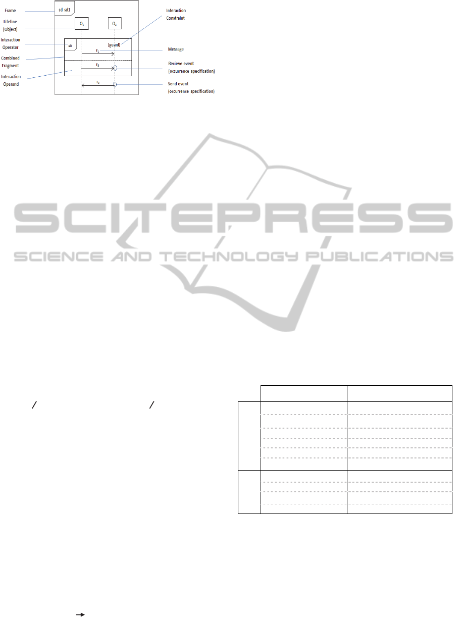
Figure 1: Structural elements of UML2 SDs with
CombinedFragments.
3.2 The Language of π-calculus
The π-calculus (Milner, 1999) is a process algebra
that provides a high expressivity power by
authorizing the passage of “channels” between
processes; it can be used for the representation, the
analysis, the verification and simulation of mobile
and concurrent systems. The π-calculus uses two
concepts of modeling; a process that is an active
communicating entity in the system, and a name that
is anything else, e.g. a communication link, variable,
data, etc. The abstract syntax for the π-calculus is
built from the following BNF grammar:
P ::= 0 Nil; Empty process
| x (y) . P Input prefix; receive y along x
| x <y> . P Output prefix; send y along x
|
τ. P Silent prefix; an internal action
| P | P Parallel composition
| P + P Non-deterministic choice
| (ν x) P Restriction of x to process P
| ! P Replication of process P
| [x = y] P Match; if x = y then P
| [x = y] P Mismatch; if x = y then P
| A(y
1
, … , y
n
) Process identifier
There are several extensions of the π-calculus, in our
paper we choose the polyadic version where a
message could consist of multiple names rather than
one.
For the convenience, we define the following
shortcuts: (1) to represent the summation of all
processes, (2) to represent the composition of all
processes, (3) to represent a series of channels and (4)
the restriction operator for multiple names in a
process as follows:
Ii
i
P
def
P
1
+ P
2
+ . . . + P
n
(1)
Ii
i
P
def
P
1
| P
2
| . . . | P
n
(2)
x
1
def
x
1
, x
2
,
.
..., x
n
(3)
(ν x
1
, x
2
,
.
..., x
n
) P
def
(ν x
1
)(ν x
2
) … (ν x
n
) P (4)
4 MAPPING OF UML2
COMBINEDFRAGMENTS INTO
THE Π-CALCULUS
In our approach, we describe the behavior of a
sequence diagram by the free merge of the semantics
of their different lifelines behaviors, so it is a lifeline-
based semantics. We consider here asynchronous
messages. We associate to each message occurrence
specification (send or receive event) of an object a
state on its lifeline (i.e. event-oriented behavior). We
consider two events on our lifelines here, the receipt
event and the sending event in contrast to (Lam et al.,
2005) while the authors build their mapping only on
the receipt event. When an event is produced, the
object switches from a state to another. By this way,
we can maintain the weak sequencing and
interleaving semantics during the mapping. In
addition, such an interpretation makes the properties
of a sequence diagram easier to check.
We start this section by a mapping of basic
elements of sequence diagrams to deal with basic
interactions. Then, we tackle the translation of
CombinedFragments and other interesting elements.
Table 1 illustrates the mapping of the essential
elements.
Table 1: Mapping of elements of UML2 SDs.
Sequence diagram π-calculus
Basic elements
lifeline Process identifier
send event Output action
receive event Input action
creation event Process creation
destruction event Nil process
message Channel
CombinedF
ragments
alt Non-deterministic choice
opt Non-deterministic choice
par Parallel execution
loop Recursive execution
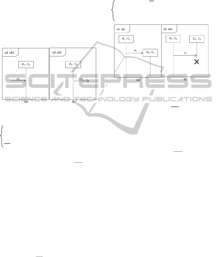
4.1 Basic Elements
We provide here the mapping of basic constructs i.e.
lifelines, messages and events (see Fig. 2). An object
(lifeline) is transformed to a π-calculus process
identifier. A message is transformed to a π-calculus
channel. Events (occurrence specification) of sending
and receiving of messages are transformed to π-
calculus output or input actions respectively. The
APi-calculus-basedApproachfortheVerificationofUML2SequenceDiagrams
89
argument vector “ m
” is used to represent all different
messages (m
1
, m
2
, ..., m
n
) handled (sent or received)
by an object during its lifeline. O
i
S
j
is the process
corresponds to the object O
i
at the state S
j
on its
lifeline. Each lifeline process identifier use two
channels to communicate messages “
m
” with the
others, one to receive actions “in
Oi
” and the other one
to send actions “out
Oi
”. We have used the last
notations “O
i
S
j
, in
Oi
, out
Oi
” to provide a readable
mapping when complex interactions are involved.
Thus, the execution semantics of a lifeline “O
1
”
is
given by the behavior of the process:
Figure 2: Mapping of basic elements.
O1
S1
(in
o1
, out
o1
,
m
)
def
in
o1
(x).([x= m
1
] O1
S2
(in
o1
, out
o1
,
m
) +
1i
[x= m
i
] O1
S1
(in
o1
,
out
o1
,
m
))
out
o1
<m
1
>.O1
S2
(in
o1
, out
o1
,
m
)
The receipt event of a message “m
1
” is
represented by the input action “in
o1
”, and the sending
event is modeled by the output action “out
o1
”. In the
first case, the process O1
S1
(in
o1
, out
o1
, m
) waits on
channel “in
o1
(x)” for an event “m
1
”
then it evolves to
another process O1
S2
(in
o1
, out
o1
, m
). Otherwise, it
proceeds as itself. In the second case, the process
O1
S1
(in
o1
, out
o1
, m
) sends a message “m
1
”
and
evolves to another process O1
S2
(in
o1
, out
o1
, m
).
4.2 CreationEvent and
DestructionEvent
A CreationEvent (Fig. 3 on left) models the creation
of a lifeline (object). We can describe the execution
semantics of the lifeline “O
1
”
by the behavior of the
process identifier with arguments O1
S1
(in
o1
, out
o1
,
m
) as follows:
O1
S1
(in
o1
, out
o1
,
m
)
def
out
o1
<m
1
>.(O1
S2
(in
o1
, out
o1
,
m
) | O2
S1
(in
o2
,
out
o2
,
m
))
A DestructionEvent (Fig. 3 on right) models the
destruction of a lifeline (object). We can describe the
execution semantics of the lifelines “O
1
” and
“O
2
” by
the behavior of the processes identifiers O1
S1
(in
o1
,
out
o1
, m
) and O2
S1
(in
o2
, out
o2
, m
)
as follows:
O1
S1
(in
o1
, out
o1
,
m
)
def
out
o1
<m
1
>.O1
S2
(in
o1
, out
o1
,
m
)
O2
S1
(in
o2
, out
o2
,
m
)
def
in
o2
(x).([x= m
1
]0 +
1i
[x= m
i
]
O2
S1
(in
o2
, out
o2
,
m
))
Figure 3: Mapping of Creation and Destruction events.
In the first case, at the beginning there is only the
process O1
S1
(in
o1
, out
o1
, m
) in execution. This last
carries the output action “out
o1
<m
1
>” that is
corresponds to the Create Message, then it behaves
like two parallel processes. One of these last,
O1
S2
(in
o1
, out
o1
, m
) is corresponding to another state
on the lifeline of the same object. The other one,
O2
S1
(in
o2
, out
o2
, m
) is corresponding to the new
object created.
In the second case, the process O1
S1
(in
o1
, out
o1
,
m
) carries the output action “out
o1
<m
1
>” that is
corresponding to the Destruction Message and it
behaves like another process O1
S2
(in
o1
, out
o1
, m
)
that is corresponding to another state on the lifeline of
the object. The process O2
S1
(in
o2
, out
o2
, m
) waits on
channel “in
o2
(x)” for an event “m
1
”, if it is the case,
it then evolves to null process “0”. Otherwise, it
proceeds as itself.
These two cases reveal some capabilities of the π-
calculus such as the dynamic creation of a process and
its dynamic destruction, which it is not possible to
represent in a so natural way in other formalisms.
4.3 Alternative CombinedFragments
The alt CombinedFragment (see Fig. 4) represents
alternative choices of behavior and one of the
operands will be chosen at most. The chosen operand
must have an explicit or implicit guard expression
that evaluates to true to enter it. In this rule, for
simplicity, we consider that no explicit guard is
defined at the moment (see interaction constraints
mapping for explicit guard), thus, we apply an
ICSOFT-PT2015-10thInternationalConferenceonSoftwareParadigmTrends
90
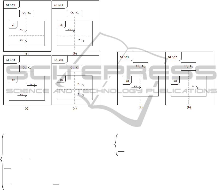
implicit true guard in the operand. In the π-calculus,
we use the non-deterministic choice to model the alt
CombinedFragment. The execution semantics of a
lifeline “O
1
”
enclosed by an alt CombinedFragment
is given by the process:
Figure 4: Mapping of alt CombinedFragment.
O1
S1
(in
o1
, out
o1
,
m
)
def
in
o1
(x).([x= m
1
] O1
S2
(in
o1
, out
o1
,
m
) + [x= m
2
] O1
S3
(in
o1
, out
o1
,
m
)
+
2,1i
[x= m
i
] O1
S1
(in
o1
, out
o1
,
m
))
in
o1
(x).([x= m
1
] O1
S2
(in
o1
, out
o1
,
m
) +
1i
[x= m
i
] O1
S1
(in
o1
,
out
o1
,
m
)) + out
o1
<m
2
>.O1
S3
(in
o1
, out
o1
,
m
)
out
o1
<m
1
>.O1
S2
(in
o1
, out
o1
,
m
) + in
o1
(x).([x= m
2
] O1
S3
(in
o1
, out
o1
,
m
) +
2i
[x= m
i
] O1
S1
(in
o1
, out
o1
,
m
))
out
o1
<m
1
>.O1
S2
(in
o1
, out
o1
,
m
) + out
o1
<m
2
>.O1
S3
(in
o1
, out
o1
,
m
)
In the first case, the process O1
S1
(in
o1
, out
o1
, m
)
waits to receive an event and depending on what is
received (m
1
or m
2
), it evolves to either O1
S2
(in
o1
,
out
o1
, m
) or O1
S3
(in
o1
, out
o1
, m
). In the second
case, the process O1
S1
(in
o1
, out
o1
, m
) waits until it
receives the message “m
1
” to proceed to another
process, or it sends a message “m
2
” and evolves to
another process in an alternative way. The third case
is similar to the second case, because we adopt the
interpretation of the OMG specification with regard
to the operands evaluation which assumes that only
one operand will evaluate to true. Our proposed
semantics guarantee that no multiple possible
executions found by using the non-deterministic
choice. In the last case, the process O1
S1
(in
o1
, out
o1
,
m
) sends a message “m
1
” and behaves
like O1
S2
(in
o1
,
out
o1
, m
) or it sends a message “m
2
” and behaves
like O1
S3
(in
o1
, out
o1
, m
).
4.4 Option CombinedFragments
The opt CombinedFragment (see Fig. 5) represents a
choice of behavior where either the sole operand
happens or nothing happens. Thus, we translate it like
we have proceeded in the alt CombinedFragment
considering only one operand. The execution
semantics of a lifeline “O
1
” enclosed by an opt
CombinedFragment is given by the process:
Figure 5: Mapping of opt CombinedFragment.
O1
S1
(in
o1
, out
o1
,
m
)
def
in
o1
(x).([x= m
1
] O1
S2
(in
o1
, out
o1
,
m
) +
1i
[x= m
i
] O1
S1
(in
o1
,
out
o1
,
m
))
out
o1
<m
1
>.O1
S2
(in
o1
, out
o1
,
m
)
4.5 Loop CombinedFragments
The loop CombinedFragment (see Fig. 6) is
composed of only one operand which is repeated a
number of times limited by a lower and an upper
value or with no bounds specified. Here, we represent
the two last cases with a guard that must be evaluated
to true to enter the operand for simplicity. We
consider that no explicit guard is defined at the
moment, thus, we apply an implicit true guard in the
operand (see interaction constraints mapping for
explicit guard). In the π-calculus, we use a recursive
approach to model the loop combinedFragment by
invoking the parent process O1
S1
(in
o1
, out
o1
, m
) at
each execution end of the operand. The execution
semantics of a lifeline “O
1
” enclosed by a loop
CombinedFragment is given by the process:
APi-calculus-basedApproachfortheVerificationofUML2SequenceDiagrams
91
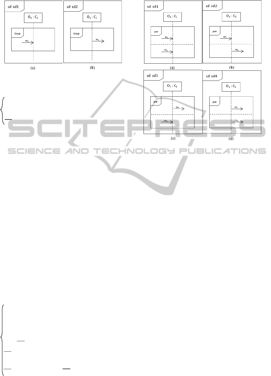
Figure 6: Mapping of loop CombinedFragment.
O1
S1
(in
o1
, out
o1
,
m
)
def
in
o1
(x).([x= m
1
] O1
S2
(in
o1
, out
o1
,
m
).O1
S1
(in
o1
, out
o1
,
m
) +
1i
[x= m
i
] O1
S1
(in
o1
, out
o1
,
m
))
out
o1
<m
1
>.O1
S2
(in
o1
, out
o1
,
m
).O1
S1
(in
o1
, out
o1
,
m
)
In the first case, the process O1
S1
(in
o1
, out
o1
, m
)
waits on channel “in
o1
(x)” to receive an event “m
1
”,
it then evolves to another process O1
S2
(in
o1
, out
o1
,
m
) which in its turn proceeds, after their execution,
as the parent process O1
S1
(in
o1
, out
o1
, m
). Otherwise,
if the receipt event is different from “m
1
”
,
it proceeds
as itself. In the second case, the process O1
S1
(in
o1
,
out
o1
, m
) sends a message “m
1
”
and evolves to
another process O1
S2
(in
o1
, out
o1
, m
) which in its turn
proceeds, after their execution, as the parent process
O1
S1
(in
o1
, out
o1
, m
).We consider here that the loop
terminates when the implicit condition evaluates to
false.
4.6 Parallel CombinedFragments
The par CombinedFragment (see Fig. 7) is composed
of at least two operands that execute in parallel. The
different events of different operands can be
interleaved as long as the ordering imposed by each
operand is preserved. In the π-calculus, we use the
parallel choice to model the par combinedFragment.
The execution semantics of a lifeline “O
1
” enclosed
by a par CombinedFragment is given by the process:
O1
S1
(in
o1
, out
o1
,
m
)
def
in
o1
(x).([x= m
1
] O1
S2
(in
o1
, out
o1
,
m
) +
1i
[x= m
i
] O1
S1
(in
o1
, out
o1
,
m
)) | in
o1
(y).([y= m
2
] O1
S3
(in
o1
, out
o1
,
m
)+
2i
[y= m
i
]
O1
S1
(in
o1
, out
o1
,
m
))
in
o1
(x).([x= m
1
] O1
S2
(in
o1
, out
o1
,
m
)+
1i
[x= m
i
] O1
S1
(in
o1
, out
o1
,
m
)) | out
o1
<m
2
>.O1
S3
(in
o1
, out
o1
,
m
)
out
o1
<m
1
>.O1
S2
(in
o1
, out
o1
,
m
) | in
o1
(x).([x= m
2
] O1
S3
(in
o1
, out
o1
,
m
)+
2i
[x= m
i
] O1
S1
(in
o1
, out
o1
,
m
))
out
o1
<m
1
>.O1
S2
(in
o1
, out
o1
,
m
) | out
o1
<m
2
>.O1
S3
(in
o1
, out
o1
,
m
)
Figure 7: Mapping of par CombinedFragment.
In the first case, the process O1
S1
(in
o1
, out
o1
, m
)
waits in parallel to receive multiple events (receipt
events) and depending on what is received (m
1
or m
2
)
it evolves in parallel to either O1
S2
(in
o1
, out
o1
, m
) or
O1
S3
(in
o1
, out
o1
, m
). In the second case, the process
O1
S1
(in
o1
, out
o1
, m
) waits until it receives the
message “m
1
” to proceed to another process
O1
S2
(in
o1
, out
o1
, m
), and in parallel, it sends a
message “m
2
” and evolves to another process
O1
S3
(in
o1
, out
o1
, m
). The third case is similar to the
second case, because the operands act as parallel. In
the last case, the process O1
S1
(in
o1
, out
o1
, m
) sends
a message “m
1
” and behaves
like O1
S2
(in
o1
, out
o1
, m
) and in parallel, it sends a message “m
2
” and behaves
like O1
S3
(in
o1
, out
o1
, m
).
4.7 Interaction Constraints
An Operand of the CombinedFragment must have an
explicit or implicit guard expression that evaluates to
true to enter it. If the operand has no guard, an implicit
true guard is implied (as in previous sub-sections). If
none of the operands has a guard that evaluates to
true, none of the operands are executed and the
remainder of the enclosing interaction fragment is
executed. We consider that if there is a guard on a
CombinedFragment, the lifelines enclosed by it must
synchronize with the one bearing the guard before
entering the CombinedFragment. Thus, the execution
semantics of a lifeline “O
1
” enclosed by a
ICSOFT-PT2015-10thInternationalConferenceonSoftwareParadigmTrends
92
CombinedFragment and bearing the guard condition
is given by the behavior of the process:
O1
S1
(in
o1
, out
o1
, guard
1
,
m
)
def
(ν true, false) (
2
n
i
guard
1
<true>.O1
S2
(in
o1
, out
o1
, guard
1
,
m
) +
2
n
i
guard
1
<false>.O1
S3
(in
o1
, out
o1
, guard
1
,
m
))
And the execution semantics of the other lifelines
“O
i
” (i=2..n) enclosed by the CombinedFragment is
given by the processes:
Oi
S1
(in
Oi
, out
Oi
, guard
1
,
m
)
def
guard
1
(z).([z=true] Oi
S2
(in
Oi
, out
Oi
,
guard
1
,
m
) + [z=false] Oi
S3
(in
Oi
, out
Oi
, guard
1
,
m
))
The process corresponds to the lifeline bearing the
guard evaluates it and sends in parallel to the
processes corresponding to the other lifelines the
results of evaluation. These last are waiting to receive
the evaluation results to behave like processes inside
or outside the operand.
4.8 Sequence Diagrams
We have now all the ingredients to define a π-calculus
representation for a full sequence diagram using the
parallel merge of the behavior of different lifelines
processes as follows:
SDname
def
(ν ds
)
j
Iji,
i
SO
O
i
S
j
is the process corresponds to the object O
i
at the
state
S
j
on its lifeline. “ ds
” are different channels
used. Thus, the behavior of the process corresponds
to the sequence diagram
SDname is given by
assembling,
as a process, the whole system formed by
a restricted composition of different processes
correspond to different objects. These last will evolve
dynamically by message passing between themselves
until no event is triggered.
5 VERIFICATION OF SEQUENCE
DIAGRAMS
5.1 Mobility Workbench Tool (MWB)
The mobility workbench MWB (Victor et al., 1994)
allows the automation of the analysis of π-calculus
specifications, thus, it can be used for:
Model checking of sequence diagrams to check
the correctness from certain properties such as
deadlock, livelock…etc.
Equivalence checking between different sequence
diagrams by verifying the equivalence between
theirs corresponding π-calculus process
expressions.
Interactive simulation of process execution.
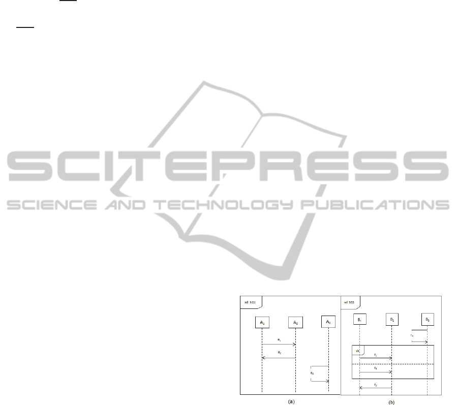
5.2 Example
Figure 8 presents an example that we have chosen in
order to show the capabilities of our approach. It
seems that it is a simple example, but the week
sequencing leads to non-intuitive meanings of the
example diagrams. In fact, events that do not belong
to the same lifeline and they are not related by a path
of messages can occur independently. This is for
example the case of “e
3
” with regard to “e
1
” and “e
2
”
in “SD1”. A message occurs above or below a
CombinedFragment does not mean necessarily that it
produced before or after those inside the
CombinedFragment. This is the case for example of
“r
4
” with regard to “r
1
” and “r
3
” in “SD2”, but this is
not the case of “r
2
” with regard to “r
1
” and “r
3
”
because they share lifelines “B1” and “B2”. In
addition, due to the weak sequencing, an empty box
is equivalent to no box. This is for example the case
of the lifeline “B3”with regard to the
alt
CombinedFragment in “SD2”. Thus, the two
diagrams have the same behavior.
Figure 8: Example of two UML SDs.
According to the mapping defined above, we
generate the π-calculus specifications corresponding
to the two diagrams (Sd1, Sd2). After that, we upload
them into the MWB tool to start the verification task.
Figure 9 shows that no deadlocks are found in the two
diagrams. It indicates also that the two diagrams (i.e.
theirs π-calculus code) are weak open bisimilar (they
have the same observed behaviour). The figure, in
addition, illustrates the ability of the execution
simulation of a diagram in this tool (i.e. the second
diagram).
APi-calculus-basedApproachfortheVerificationofUML2SequenceDiagrams
93
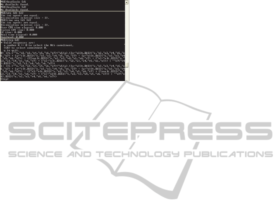
Figure 9: Verification results.
6 CONCLUSIONS
In this paper we have proposed a systematic mapping
of UML2 sequence diagrams into the π-calculus
formalism. We have deliberately taken the choice of
the π-calculus because besides its rich theory and
background especially for systems with dynamic
structures, it is well adapted to capture the
interleaving semantics of the interactions. This allows
automatic analysis and verification of these diagrams
using π-calculus analytic tools such as the mobility
workbench (MWB). Our approach provides the
mapping of basic elements as well as the mostly used
CombinedFragments. The mechanism adopted in the
mapping is simple and effective. It is a lifeline based-
semantics; this means that the sequence diagram
behavior is described by the free merge of their
lifelines behaviors. A lifeline behavior is event-
oriented and we consider two events on the lifelines;
the receipt event and the send event. By this way, the
approach gives flexibility and clarity in the
verification task and each one who would like to use
our approach could write very expressive properties.
In our future works, we plan to extend our
approach by the translation of the rest
CombinedFragments of sequence diagrams and to
automate the mapping to maximize the potential
impact of the work.
REFERENCES
Alawneh, L., Debbabi, M., Hassaine, F., Jarraya, Y.,
Soeanu, A., 2006. A unified approach for verification
and validation of systems and software engineering
models. In ECBS, pages 409–418.
Bouabana, T., T., Rubin, S., H., 2013. An interleaving
semantics for UML 2 interactions using Petri nets.
Information Sciences, vol. 232 pp. 276–293.
Damm, W., Harel, D., 2001. LSCs: breathing life into
message sequence charts. Form. Methods Syst. Des. 19
(1) 45–80.
Dan, L., Danning, L., 2010. An Approach to Formalize
UML Sequence Diagrams in CSP. 3rd International
Conference on Computer and Electrical Engineering
(ICCEE).
Eichner, C., Fleischhack, H., Meyer, R., Schrimpf, U.,
Stehno, C., 2005. Compositional semantics for UML
2.0 Sequence Diagrams using Petri Nets. In: SDL2005:
Model Driven Systems Design. Springer, New York.
International Telecommunication Union. ITU-TS,
Recommendation Z.120, 1993. Message Sequence
Chart (MSC). ITU-TS, Geneva, September.
Knapp, A., Wuttke, J., 2006. Model checking of UML 2.0
interactions. In: Kühne, T. (ed.) Models in Software
Engineering, Workshops and Symposia at MoDELS,
Springer, New York, pp. 42–51.
Lam, V., Padget, J., 2005. Consistency Checking of
Sequence Diagrams and Statechart Diagrams Using the
π-Calculus. IFM, LNCS 3771, pp. 347–365.
Lima, V., Talhi, C., Mouheb, D., Debbabi, M., Wang, L.,
2009. Formal Verification and Validation of UML 2.0
Sequence Diagrams using Source and Destination of
Messages. Electronic Notes in Theoretical Computer
Science 254, 143–160.
Micskei, Z., Waeselynck, H., 2011. The many meanings of
UML 2 sequence diagrams: a survey. J. Softw. Syst.
Model. Springer 10 (4) 489–514.
Milner, R., 1999. Communicating and Mobile Systems:
The π-calculus. Cambridge University Press.
Object Management Group (OMG), “Unified Modeling
Language”, Superstructure, version 2.4,
http://www.omg.org/spec/UML/2.4, 2011.
Pokozy-Korenblat, K., Priami, C., 2004. Toward Extracting
π-calculus from UML Sequence and State Diagrams.
Electronic Notes in Theoretical Computer Science
vol.101 pp. 51–72.
Shen, H., Robinson, M., Niu, J., 2012. Formal analysis of
sequence diagram with combined fragments. In
ICSOFT (pp. 44-54).
Victor, B., Moller, F., 1994. The Mobility Workbench - A
Tool for the π-calculus. In D. Dill, ed., Proceedings of
the Conference on Computer-Aided Verification
(CAV'94), volume 818 of LNCS, pages 428- 440.
Springer Verlag.
ICSOFT-PT2015-10thInternationalConferenceonSoftwareParadigmTrends
94
