
An Approach for the Semi-automated Derivation of
UML Interaction Models from Scenario-based Runtime Tests
Thorsten Haendler, Stefan Sobernig and Mark Strembeck
Institute for Information Systems and New Media
Vienna University of Economics and Business, WU Vienna, Austria
{firstname.lastname}@wu.ac.at
Keywords:
Test-based Documentation, Scenario-based Testing, Test-Execution Trace, UML Interactions, UML Sequence
Diagram.
Abstract:
Documenting system behavior explicitely using graphical models (e.g. UML activity or sequence diagrams)
facilitates communication about and understanding of software systems during development or maintenance.
Creating graphical models manually is a time-consuming and often error-prone task. Deriving models from
system-execution traces, however, suffers from the problem of model-size explosion. We propose a model-
driven approach for deriving behavior documentation in terms of UML interaction models from runtime tests
in a semi-automated manner. Key to our approach is leveraging the structure of scenario-based tests for model
and diagram derivation. Each derived model represents a particular view on the test-execution trace. This way,
one can benefit from derived graphical models while making the resulting model size manageable. In this
paper, wedefine conceptual mappings between atest-execution trace metamodel and the UML2 metamodel. In
addition, we provide means to turn selected details of test specifications and of testing environment into views
on the test-execution trace (scenario-test viewpoint). The feasibility of our approach is demonstrated by a
prototype implementation (KaleidoScope), which builds on an existing software-testing framework (STORM)
and model transformations (Eclipse M2M/QVTo).
1 INTRODUCTION
Scenarios describe intended or actual behavior of
software systems in terms of action and event se-
quences. Notations for defining and describing sce-
narios include different types of graphical models
such as UML activity and UML interaction models.
Scenarios are used to model systems from a user per-
spective and ease the communication between differ-
ent stakeholders (Jacobson, 1992; Jarke et al., 1998;
Carroll, 2000). As it is almost impossible to com-
pletely test a complex software system, one needs an
effective means to select relevant tests, to express and
to maintain them, as well as to automate tests when-
ever possible. In this context, scenario-based testing
is a means to reduce the risk of omitting or forget-
ting relevant test cases, as well as the risk of insuf-
ficiently describing important tests (Ryser and Glinz,
1999; Nebut et al., 2006).
Tests and a system’s source code (including the
comments in the source code) directly serve as a
documentation for the respective software system.
For example, in Agile development approaches, tests
are sometimes referred to as a living documentation
(Van Geet et al., 2006). However, learning about a
system only via tests and source code is complex and
time consuming.
In this context, graphical models are a popular
means to document a system and to communicate
its architecture, design, and implementation to other
stakeholders, especially those who did not author the
code or the tests. Moreover, graphical models also
help in understanding and maintaining a system, e.g.,
if the original developers are no longer available or if
a new member of the development team is introduced
to the system.
Alas, authoring and maintaining graphical mod-
els require a substantial investment of time and ef-
fort. Because tests and source code are primary de-
velopment artifacts of many software systems, the au-
tomated derivation of graphical models from a sys-
tem’s tests and source code can contribute to limiting
documentation effort. Moreover, automating model
derivation provides for an up-to-date documentation
of a software system, whenever requested.
A general challenge for deriving (reverse-
Haendler T., Sobernig S. and Strembeck M..
An Approach for the Semi-automated Derivation of UML Interaction Models from Scenario-based Runtime Tests.
DOI: 10.5220/0005519302290240
In Proceedings of the 10th International Conference on Software Engineering and Applications (ICSOFT-2015), pages 229-240
ISBN: 978-989-758-114-4
Copyright
c
2015 by SCITEPRESS - Science and Technology Publications, Lda.
engineering) graphical models is that their visualiza-
tion as diagrams easily becomes too detailed and too
extensive, rendering them ineffective communication
vehicles. This has been referred to as the problem of
model-size explosion (Sharp and Rountev, 2005; Ben-
nett et al., 2008). Common strategies to cope with un-
manageable model sizes are filtering techniques, such
as element sampling and hiding.
Another challenge is that a graphical documenta-
tion (i.e. models, diagrams) must be captured and vi-
sualized in a manner which makes the resulting mod-
els tailorable by the respective stakeholders. This
way, stakeholders can fit the derived models to a cer-
tain analysis purpose, e.g., a specific development or
maintenance activity (Falessi et al., 2013).
Kaleido
Scope
System
under Test
UML Sequence
Diagrams
Scenario-Test
Speci
cation
UML Interaction
Models
Stakeholder
selects
views
Figure 1: Deriving models from scenario tests.
In this paper, we report on an approach for de-
riving behavior documentation (esp. UML2 interac-
tion models depicted via sequence diagrams) from
scenario-based runtime tests in a semi-automated
manner (see Fig. 1). Our approach is independent
of a particular programming language. It employs
metamodel mappings between the concepts found
in scenario-based testing, on the one hand, and the
UML2 metamodel fragment specific to UML2 in-
teractions (Object Management Group, 2011b), on
the other hand. Our approach defines a viewpoint
(Clements et al., 2011) which allows for creating
different views on the test-execution traces resulting
in partial interaction models and sequence diagrams.
Moreover, we present a prototypical realization of the
approach via a tool called KaleidoScope
1
.
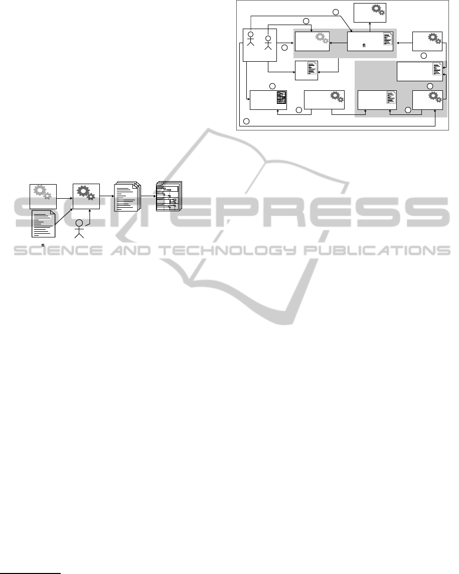
Fig. 2 visualizes the process of deriving tailorable
interaction models from scenario-based runtime tests.
After implementing the source code and correspond-
ing scenario tests, the respective tests are executed
(see steps
1
and
2
in Fig. 2). A so-called “trace
provider” component observes the test run and ex-
tracts the execution-trace data
2
for creating a corre-
sponding scenario-test trace model (see step
3
). Af-
ter test completion, the test log is returned (including
the test result). Based on a configured view and based
1
Available for download from our website (Haendler,
2015).
2
For the purposes of this paper, a trace is defined as a se-
quence of interactions between the structural elements of
the system under test (SUT), see e.g. (Ziadi et al., 2011).
develops
uses
Tester
Developer
Stakeholder
selects view
System
under Test
Test
Framework
Scenario-Test
Speci
cation
Trace
Provider
Interaction
Model
Sequence
Diagram
setup
sd run2
precond.
postcond.
testbody
cleanup
Test Run
Model
Builder
Scenario-Test
Trace Model
Diagram
Editor
Test
Log
tests
observes
creates
uses
uses
creates
prints
analyses
analyses
returns
1
starts
2
3
4
5
67
8
specifies
Model-to-Model
Transformation
1
Figure 2: Conceptual overview of deriving tailorable inter-
action models from scenario-based runtime tests.
on the derived trace model (see steps
4
and
5
), the
“model builder” creates a tailored interaction model
(step
6
) which can be rendered in a diagram editor
(step
7
) to assist in analysis tasks by the stakehold-
ers (step
8
). Notice that based on one test run, mul-
tiple models can be derived in steps
4
through
7
.
The remainder of this paper is structured as fol-
lows: In Section 2, we explain how elements of sce-
nario tests can be represented as elements of UML2
interactions. In particular, we introduce in 2.1 our
metamodel of scenario-based testing and in 2.2 the
elements of UML2 metamodel that are relevant for
our approach. In 2.3, we explain conceptual map-
pings between different elements of scenario tests and
UML2 interaction models. Subsequently, Section 3
proposes test-based tailoring techniques for the de-
rived interaction models. In Section 3.1, we explain
the tailoring options based on a scenario-test view-
point and describe a simple example in Section 3.2.
Section 3.3 explains how tailoring interaction models
is realized by view-specific mappings. In Section 4,
we introduce our prototypical implementation of the
approach. Finally, Section 5 gives an overview of re-
lated work and Section 6 concludes the paper.
2 REPRESENTING SCENARIO
TESTS AS UML2
INTERACTIONS
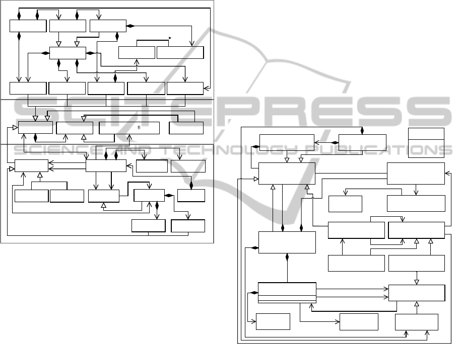
2.1 Scenario-Test Structure and Traces
We extended an existing conceptual metamodel of
scenario-based testing (Strembeck, 2011). This ex-
tension allows us to capture the structural elements
internal to scenario tests, namely test blocks, ex-
pressions, assertions, and definitions of feature calls
into the system-under-test (SUT; see Fig. 3). A
trace describes the SUT’s responses to specific stim-
uli (Clements et al., 2011). We look at stimuli which
are defined by an executable scenario-test specifica-
tion and which are enacted by executing the corre-
sponding scenario test. In the following, we refer
to the combined structural elements of the scenario-
test specifications and the underlying test-execution
infrastructure as the scenario-test framework (STF).
1
1..*
1..*
*
+definition
1
1
1
TestSuite
TestCase
TestScenario
TestPart
TestResult
ExpectedResult
Setup
Precondition
TestBody
Postcondition
Cleanup
Block
Assertion
Expression
FeatureCallDe nition
+target
1
*
+callee
1
* *
*
1
1
+source
1
1
1
*
+caller
1
Class
Feature
FeatureCall
Instance
ReturnValue
Argument
Trace
0..1
0..1
checkedAgainst
{ordered}
{ordered}
/owning
Block
/owned
Calls
0..1
*
1..*
0..1
0..1 0..1 0..1 0..1
+body
1..*
1..*
Operation
Property
Constructor
Destructor
+owningClass
1
*
+owned
Feature
0..1
+definingClass
1
{ord.}
0..1
1..*
Scenario-Test Framework
Scenario-Test Traces
Block
Structure
Figure 3: Test-execution trace metamodel extends (Strem-
beck, 2011) to include internal block structure and scenario-
test traces.
This way, an execution of a scenario-based
Test-
Suite
(i.e. one test run) is represented by a
Trace
instance. In particular, the respective trace records in-
stances of
FeatureCall
in chronological order, de-
scribing the SUT feature calls defined by the corre-
sponding instances of
FeatureCallDefinition
that
are owned by a block. Valid kinds of
Block
are
Assertion
(owned by
Pre-
or
Postcondition
) or
other STF features such as
Setup
,
TestBody
or
Cleanup
in a certain scenario test. In turn, each SUT
Feature
represents a kind of
Block
which aggre-
gates definitions of SUT feature calls. Instances of
FeatureCall
represent one interaction between two
structural elements of the SUT. These
source
and
target
elements are represented by instantiations of
Instance
. Every feature call maintains a reference
to the calling feature (
caller
) and the corresponding
called feature (
callee
), defined and owned by a given
class of the SUT.
Features
are divided into structural
features (e.g.
Property
) and behavioral features (e.g.
Operation
). Moreover,
Constructor
and
Destruc-
tor
owned by a class are also kinds of
Feature
. A
feature call additionally records instances of
Argu-
ment
that are passed into the called feature, as well as
the return value, if any. The sum of elements specific
to a call is referred to as “call dependencies”.
2.2 Interaction-specific Elements of
UML2
UML interaction models and especially sequence di-
agrams offer a notation for documenting scenario-test
traces. A UML
Interaction
represents a unit of be-
havior (here the aforementioned trace) with focus on
message interchanges between connectable elements
(here SUT instances). In this paper, we focus on a
subset of interaction-specific elements of the UML2
metamodel that specify certain elements of UML2 se-
quence diagrams (see Fig. 4).
+message
0..*
1
0..1
+sendEvent
0..1
0..1
+receiveEvent
0..1
1
*
+lifeline
0..1
+formalGate
*
0..2
+message
0..1
*
+represents
1
*
+type
1
*
+signature
0..1
+covered
*
+coverdBy
*
0..1
+fragment
*
0..1
+operand
1..*
Message
(from BasicInteractions)
+messageSort: MessageSort [1]
<<enumeration>>
MessageSort
synchCall
reply
createMessage
deleteMessage
0..1
+fragment
*
0..1
*
+cfragment
Gate
+enclosing
Operand
{ordered}
{ordered}
{ordered}
{ordered}
+event
1..*
+covered
1
Value
(from Kernel)
Occurrence
(from BasicInteractions)
Lifeline
(from BasicInteractions,
Fragments)
Gate
(from Fragments)
NamedElement
(from Kernel)
MessageEnd
(from BasicInteractions)
MessageOccurrence
(from BasicInteractions)
InteractionFragment
(from BasicInteractions,
Fragments)
ConnectableElement
(from BasicComponents)
Class
(from Kernel)
CombinedFragment
(from Fragments)
InteractionOperand
(from Fragments)
Interaction
(from BasicInteractions,
Fragments)
0..1
+argument
*
Execution
(from BasicInteractions)
ExecutionOccurrence
(from BasicInteractions)
+start
1
*
+finish 1
*
0..2
1
+execution
Figure 4: Selected interaction-specific elements of UML2
metamodel.
The participants in a UML interaction model are
instances of UML classes which are related to a given
scenario test. The sequence diagram then shows the
interactions between these instances in terms of ex-
ecuting and receiving calls on behavioral features
(e.g. operations) and structural features (e.g. proper-
ties) defined for these instances via their correspond-
ing UML classes. From this perspective, the in-
stances interacting in the scenario tests constitute the
SUT. Instances which represent structural elements of
the scenario-testing framework (STF; e.g. test cases,
postconditions), may also be depicted in a sequence
diagram; for example as a test-driver lifeline (Cor-
nelissen et al., 2007). The feature calls on SUT in-
stances originating from STF instances rather than
other SUT instances represent the aforementioned
stimuli. This way, such feature calls designate the be-
ginning and the end of a scenario-test trace.
2.3 Mapping Test Traces to Interactions
To transform scenario-test traces into UML inter-
actions, we define a metamodel mapping based on
the scenario-test trace metamodel, on the one hand,
and the corresponding excerpt from the UML2 meta-
model, on the other hand.
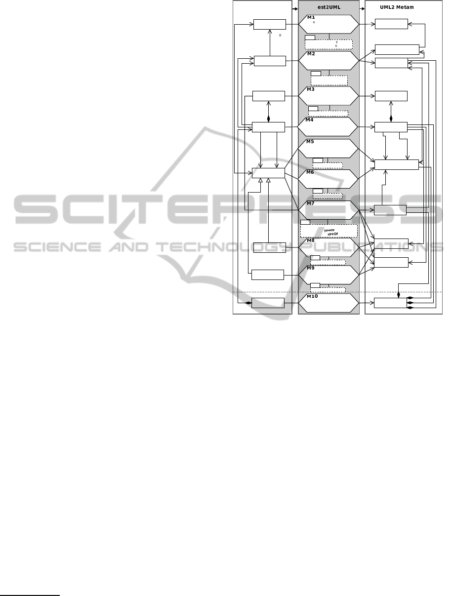
For the purposes of this paper, we formalized
the corresponding mappings using transML dia-
grams (Guerra et al., 2013). transML diagrams repre-
sent model transformations in a tool- and technology-
independent manner compatible with the UML. In to-
tal, 18 transML mapping actions are used to express
the correspondences. These mapping actions (M1–
M18) are visualized in Figures 5, 6 and 12.
The transML mapping diagrams are amended
by OCL expressions (Object Management Group,
2014b) to capture important mapping and consistency
constraints for the resulting UML interaction models.
The mapping constraints are depicted below each re-
lated transML mapping action, which represents the
context for the OCL constraints and, this way, allows
for navigating to elements of the input and output
model. To improve diagram readability, the constraint
expressions are omitted in the mapping diagrams pre-
sented in this paper.
3
In general, i.e. independent of a particular view,
each
Trace
instance, which comprises one or several
feature calls, is mapped to an instance of UML
In-
teraction
(see
M10
in Fig. 5). This way, the result-
ing interaction model reflects the entire test-execution
trace (for viewpoint mappings, see Subsection 3.3).
However, each instance of
FeatureCall
(
fC
) con-
tained by a given trace is mapped to at least one UML
Message
instance (see
M4
). Each of the mappings of
the other trace elements (i.e. “call dependencies”) de-
pends on mapping
M4
and is specific to
fC
.
Each instance that serves as
source
or
tar-
get
of a feature call is captured in terms of a pair
of a
ConnectableElement
instance and a
Life-
line
instance. A
Lifeline
, therefore, represents
a participant in the traced interaction, i.e., a
Con-
nectableElement
typed with the UML class of the
participant. See the transML mapping actions
M1
and
M2
in Fig. 5.
3
However, the OCL constraints are fully reported in an ex-
tended version of this paper (Haendler, 2015).
1
OCL
instance=fC.source or
instance=fC.target
Scenario-Test
Metamodel
odel
T
Argument
FeatureCall
Feature
Instance
Class
Value
Message
MessageOccurrence
ConnectableElement
Lifeline
Class
+argument
+receiveEv.
1
+event
*
+cov.
1
+repr.
1
+type
1
+callee
1
+target
1
1
1 1
1
* *
+owningClass
1
*
+owned
Feature
NamedElement
Execution
MessageSort
+start
sendEv.
receiveEv.
synchCall
deleteM.
createM.
+source
1
*
*
*
*
+caller
1
+sendEv.
1
1
+signature
1
Trace
Interaction
*
fragment
*
*
*
*
+fragment
*
Constructor
Destructor
*
+covered
1
A de nition of source or target
instance is mapped to a class
A source or target instance is
mapped to a connectable element
represented by a lifeline
A feature call (fC) is mapped
to a message
A calling feature is mapped to
a message occurrence as
send event
A called feature is mapped to
a message occurrence as
receive event
A called feature that
is neither constructor nor destructor
is mapped to execution,
signature and message sort
A called constructor is mapped
to signature and message sort
A called destructor is mapped
to signature and message sort
A trace is mapped to an
interaction
An argument is mapped to a value
1
OCL
class=fC.source.de
nition or
class=fC.target.de
nition
OCL
argument=fC.argument
OCL
feature=fC.caller
OCL
feature=fC.callee and not
(feature.oclIsT (Constructor)
or feature.oclIsT
(Destructor))
OCL
constructor=fC.callee
OCL
feature=fC.callee
OCL
destructor=fC.callee
+de
ning
Class
*
Figure 5: Mapping elements of scenario-test traces specific
to a feature call (
fC
).
An instance of
MessageOccurrence
in the result-
ing interaction model represents the feature call at
the calling feature’s end as a
sendEvent
(see
M5
).
Likewise, at the called feature’s end, the feature call
maps to a
receiveEvent
(see
M6
). Depending on
the kind of the feature call, the resulting
Message
in-
stance is annotated differently. For constructor and
destructor calls, the related message has a «
create
»
or «
delete
»
signature
, respectively. In addition,
the corresponding message is marked using
mes-
sageSort createMessage
or
deleteMessage
, re-
spectively (see
M8
and
M9
). Note that in case of a con-
structor call, the
target
is represented by the class of
the created instance and the created instance is the re-
turn value. This way, here, the return value is mapped
to lifeline and connectable element typed by the
tar-
get
(see
M8
).
Other calls map to synchronous messages (i.e.
messageSort synchCall
). In this case, the name of
the
callee
feature and the names of the arguments
passed into the call are mapped to the
signature
of
the corresponding
Message
instance (see
M7
). In addi-
tion, an execution is created in the interaction model.
An
Execution
represents the enactment of a unit of
behavior within the lifeline (here the execution of a
called feature). The resulting
Execution
instance be-
longs to the lifeline of the
target
instance and its
start
is marked by the message occurrence created
by applying
M6
.
FeatureCall
ReturnValue
Message
MessageOccurrence
ExecutionOccurrence
Execution
(see M7)
NamedElement
MessageSort
+finis
+signature
+receiveEv.
receiveEv.
+sendEv.
sendEv.
Instance Lifeline
+covered1
+covered
1
+source
1
+target
1
OCL
fC.returnValue->isEmpty()
OCL
returnValue=fC.returnValue
Trace
Interaction
*
*
*
*
+fragment
*
+fragment
*
1
1
1
1
1
+frgm.
*
+finis
+covered
1
see M2
see M10
M11
M12
A feature call is mapped to
execution occurrence if no
return value exists
A return value is mapped to
message, to signature and
message sort and to message
occurrences as send and
receive event
Test2UML
Scenario-Test
Metamodel
UML2 Metamodel
1
Figure 6: Mapping return value specific to a feature call
(
fC
).
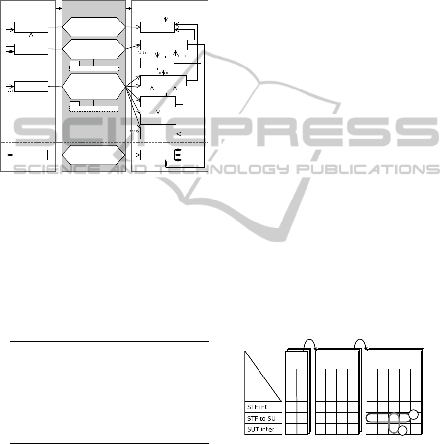
If a given feature call
fC
reports a return value,
a second
Message
instance will be created to rep-
resent this return value. This second message is
marked as having
messageSort reply
(see
M12
in
Fig. 6). Moreover, two instances of
MessageOccur-
rence
are created acting as the
sendEvent
and the
receiveEvent
(covering the lifelines mapped from
target
and
source
instance related to
fC
, respec-
tively). Listing 1 provides, for instance, the corre-
sponding excerpt from the consistency constraints.
Listing 1: Excerpt from OCL consistency constraints based
on mapping
M12
in Fig. 6.
1
context
M12
inv
:
2 message.sendEvent .
oclIsTypeOf
(
MessageOccurrenceSpecification )
and
3 message.sendEvent .covered .represents .name = returnValue
.featureCall .target.name
and
4 message.sendEvent .covered .represents .type.name =
returnValue .featureCall .target.definingClass .name
and
5 message.receiveEvent .
oclIsTypeOf
(
MessageOccurrenceSpecification )
and
6 message.receiveEvent .covered.represents .name =
returnValue .featureCall .source.name
and
7 message.sendEvent .covered .represents .type.name =
returnValue .featureCall .source.definingClass .name
An instance of
NamedElement
acts as the
sig-
nature
of this message, reflecting the actual return
value (see
M12
). In case of a missing return value, an
ExecutionOccurrence
instance is provided to con-
sume the call execution (
finish
) at the called fea-
ture’s end (see
M11
).
The chronological order of the
FeatureCall
in-
stances in the recorded trace must be preserved in
the interaction model. Therefore we require that
the message occurrences serving as
send
and
re-
ceiveEvents
of the derived messages (see
M5
,
M6
,
M12
) preserve this order on the respective lifelines
(along with the execution occurrences). This means,
that after receiving a message (
receiveEvent
), the
send events derived from called nested features are
added in form of events covering the lifeline. In case
of synchronous calls with owned return values, for
each message, the receive event related to the reply
message enters the set of ordered events (see
M12
) be-
fore adding the send event of the next call.
3 VIEWS ON TEST-EXECUTION
TRACES
In this section, we discuss how the mappings from
Section 2 can be extended to render the derived in-
teraction models tailorable. By tailoring, we refer to
specific means for zooming in and out on selected
details of an interaction model; and for pruning se-
lected details. For this purpose, our approach defines
a scenario-test viewpoint.
A viewpoint (Clements et al., 2011) stipulates the
element types (e.g. scenario-test parts, feature-call
scopes) and the types of relationships between these
element types (e.g. selected, unselected) available for
defining different views on test-execution traces. On
the one hand, applying the viewpoint allows for con-
trolling model-size explosion. On the other hand, the
views offered on the derived models can help tailor
the corresponding behavior documentation for given
tasks (e.g. test or code reviews) and/or stakeholder
roles (e.g. test developer, software architect).
t. suite sp. test case
setup
cleanup
setup
precond.
postcond.
cleanup
stackTest pushElement
sp. test scenario
test body
setup
precond.
postcond.
cleanup
pushOnFullStack
T
n
ern
test
parts
call
scopes
✓ ✓ ✓ ✓
✓
1
2
contains
one or many
contains
one or many
multiple
test runs
Figure 7: Example of option space for defining views on
test-execution traces, by combining scenario-test parts and
feature-call scopes.
3.1 Scenario-Test Viewpoint
To tailor the derived interaction models, two char-
acteristics of scenario tests and the corresponding
scenario-test traces can be leveraged: the whole-part
structure of scenario tests and trackable feature-call
scopes.
Scenario-test Parts. Scenario tests, in terms of con-
cepts and their specification structure, are composed
of different parts (see Section 2.1 and Fig. 3):
• A test suite encompasses one or more test cases.
• A test case comprises one or more test scenarios.
• A test case, and a test scenario can contain asser-
tion blocks to specify pre- and post-conditions.
• A test suite, a test case, and a test scenario can
contain exercise blocks, as setup, or cleanup pro-
cedures.
• A test scenario contains a test body.
Feature-call Scopes. Each feature call in a scenario-
test trace is scoped according to the scenario-test
framework (STF) and the system under test (SUT),
respectively, as the source and the target of the fea-
ture call. This way, we can differentiate between three
feature-call scopes:
• feature calls running from the STF to the SUT (i.e.
test stimuli),
• feature calls internal to the SUT (triggered by test
stimuli directly and indirectly),
• feature calls internal to the STF.
The scenario-test parts and feature-call scopes
form a large option space for tailoring an interaction
model. In Figure 7, these tailoring options are visu-
alized as a configuration matrix. For instance, a test
suite containing one test case with just one included
test scenario offers 14,329 different interaction-model
views availablefor configurationbased on one test run
(provided that the corresponding test blocks are spec-
ified).
4
In the subsequent section, we demonstrate by ex-
ample the relevance of specifying different views on
the test-execution traces for different tasks and/or
stakeholder roles.
Stac
oolean
le
eger
+full(
lean
ements
er
Figure 8: UML
class diagram of
exemplary SUT.
Listing 2: Natural-language no-
tation of scenario
pushOnfull-
Stack
.
1
Given: '
that a specific
instance of Stack
contains elements of the
size of 2 and has a limit
of 2
'
2
When: '
an element is pushed on
the instance of Stack
'
3
Then: '
the push operation
fails and the size of
elements is still 2
'
4
The number of views computes as follows: There are (2
3
−
1) non-empty combinations of the three feature-call scopes
(SUT internal, STF internal, STF to SUT) times the (2
11
−
1) non-empty combinations of at least 11 individual test
parts (e.g. setup of test case, test body of test scenario).
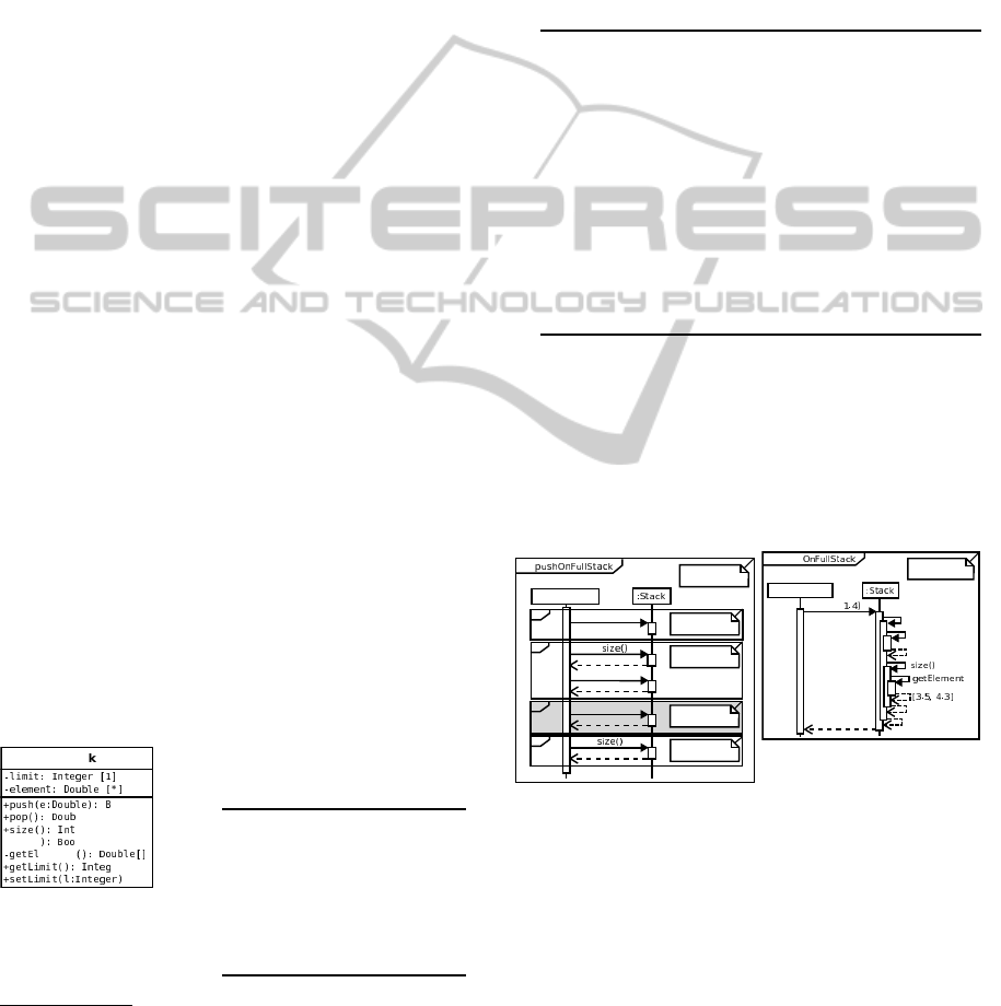
3.2 Example
Consider the example of a test developer whose pri-
mary task is to conduct a test-code review. For this
review, she is responsible for verifying a test-scenario
script against a scenario-based requirements descrip-
tion. The scenario is named
pushOnFullStack
and
specified in Listing 2. The test script to be reviewed
is shown in Listing 3.
Listing 3: Test scenario
pushOnfullStack
.
1
# It is provided in the setup script of the owning test
case pushElement that an instance of Stack exists
containing the two elements 3.5 and 4.3
2
set
fs [::STORM::TestScenario
new
-name pushOnFullStack
-testcase pushElement ]
3 $fs expected_result
set
0
4 $fs setup_script
set
{
5 [::Stack
info
instances ] limit
set
2
6 }
7 $fs preconditions
set
{
8 {
expr
{[[ ::Stack
info
instances ] size] == 2}}
9 {
expr
{[[ ::Stack
info
instances ] limit
get
] == 2}}
10 }
11 $fs test_body
set
{
12 [::Stack
info
instances ] push 1.4
13 }
14 $fs postconditions
set
{
15 {
expr
{[[ ::Stack
info
instances ] size] == 2}}
16 }
The small system under test (SUT), a stack-based
dispenser component, is visualized in Fig. 8 as a UML
class diagram. A
Stack
provides the operations
push
,
pop
,
size
, and
full
as well as the attributes
limit
and
element
. Attributes are accessible via corre-
sponding getter/setter operations (i.e.
getElements
,
getLimit
and
setLimit
).
sd
getLimit()
2
2
2
setLimit(2)
test
:TestDriver
setup
scenario
preconditions
push(1.4)
false
postcond.
test body
Figure 9: Sequence diagram
derived from
pushOnfull-
Stack
highlighting calls
running from STF to SUT.
push(
false
full()
getLimit()
2
true
s()
2
test body
sd push
:TestDriver
Figure 10: Sequence dia-
gram derived from
pushOn-
fullStack
zooming in on
test body and representing
both, calls running from
STF to SUT and calls inter-
nal to the SUT.
To support her in this task, our approach can pro-
vide her with a partial UML sequence diagram which
depicts only selected details of the test-execution
trace. These details of interest could be interactions
triggered by specific blocks of the test under review,
for example. Such a view provides immediate ben-
efits to the test developer. The exemplary view in
Figure 9 gives details on the interactions between the
STF and the SUT, i.e. the test stimuli observed under
this specific scenario. To obtain this view, the con-
figuration pulls feature calls from a combination of
setup, precondition, test body and postcondition spe-
cific to this test scenario. The view from Figure 9
corresponds to configuration
1
in Figure 7.
As another example, consider a software architect
of the same SUT. The architect might be interested
in how the system behaves when executing the test
body of the given scenario
pushOnFullStack
. The
architect prefers a behavior documentation which ad-
ditionally provides details on the interaction between
SUT instances. A sequence diagram for such a view
is presented in Figure 10. This second view effec-
tively zooms into a detail of the first view in Figure 9,
namely the inner workings triggered by the message
push(1,4)
. The second view reflects configuration
2
in Figure 7.
3.3 Viewpoint Mappings
UML interaction models and corresponding sequence
diagrams allow for realizing immediate benefits from
a scenario-test viewpoint. For example, sequence di-
agrams provide notational elements which can help
in communicating the scenario-test structure (suite,
case, scenario) to different stakeholders (architects,
developers, and testers). These notational features in-
clude combined fragments and references. This way,
a selected part can be visually marked in a diagram
showing a combination of test parts (see, e.g., Fig. 9).
Alternatively, a selected part of a scenario test can be
highlighted as a separate diagram (see Fig. 10).
On the other hand, interaction models can be tai-
lored to contain only interactions between certain
types of instances. Thereby, the corresponding se-
quence diagram can accommodate views required by
different stakeholders of the SUT. In Fig. 9, the se-
quence diagram highlights the test stimuli triggering
the test scenario
pushOnfullStack
, whereas the di-
agram in Fig. 10 additionally depicts SUT internal
calls.
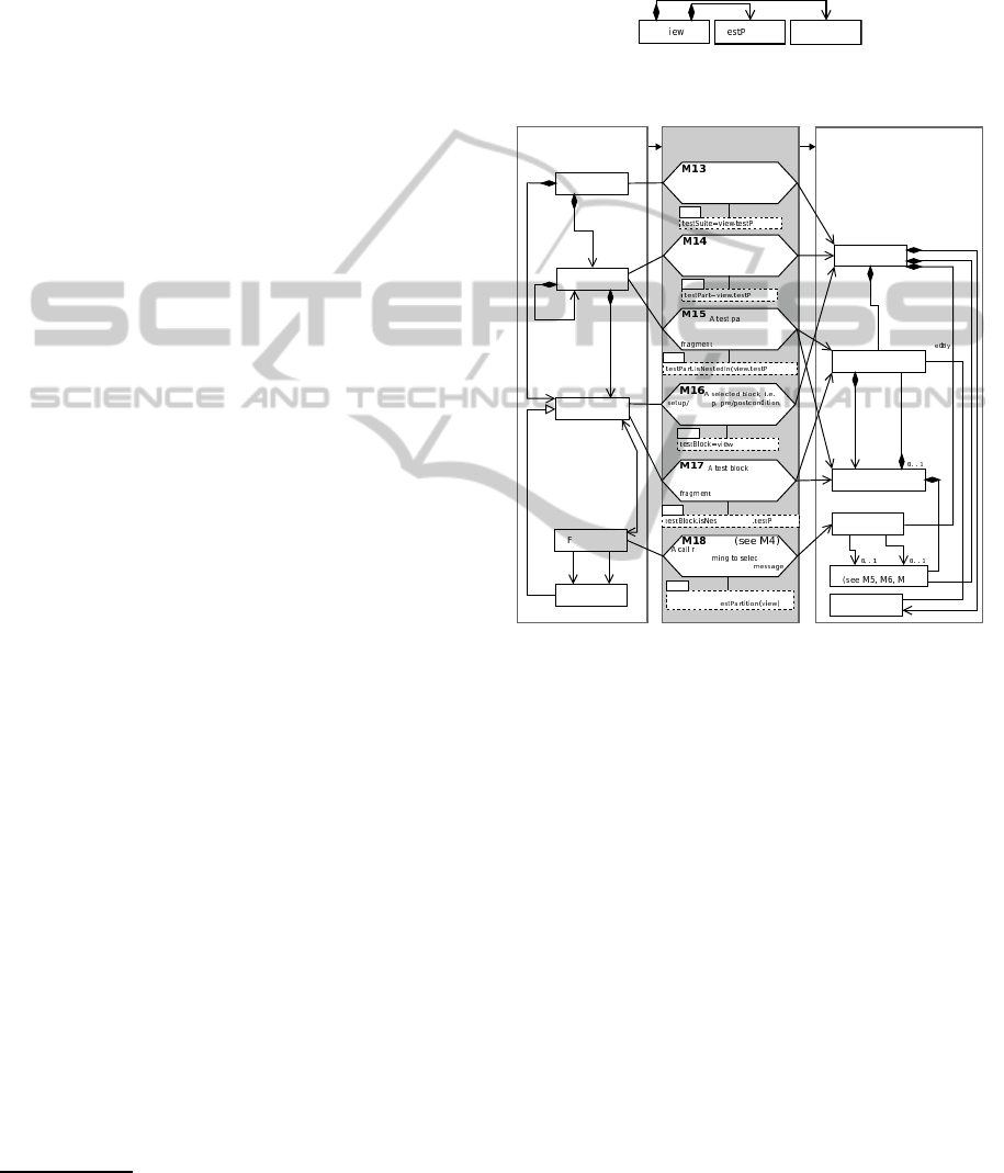
Conceptually, we represent different views as
models conforming to the view metamodel in Fig. 11.
In essence, each view selects one or more test parts
and feature-call scopes, respectively, to be turned into
an interaction model. Generating the actual partial
interaction model is then described by six additional
transML mapping actions based on a view and a trace
model (see M13–18 in Fig. 12).
5
In each mapping
action, a given view model (
view
) is used to verify
5
For details of the corresponding OCL constraints, see the
extended version of this paper (Haendler, 2015).
whether a given element is to be selected for the cho-
sen scope of test parts and call scopes. Upon its selec-
tion, a feature call with its call dependencies is pro-
cessed according to the previously introduced map-
ping actions (i.e.
M1-M9
,
M11
, and
M12
).
V
T artition
CallScope
*
*
Figure 11: View metamodel.
Scenario-Test
Metamodel
UML2 Metamodel Test2UML
TestSuite
TestPart
Interaction
CombinedFragment
InteractionOperand
*
+fragment
*
+operand
1
+fragment
*
+enclosing
Operand
/owningBlock
/ownedCalls
*
* *
Block
Message
Feature
+callee
1
Lifeline
(see M2)
MessageOccurrence
+cover
*
+covered
*
+fragm.
*
+caller
1
+sendEv. +recEv.
eatureCall
+fragm.
*
1
+lifeline
*
*
*
A selected test suite is mapped
to an interaction
(see M10)
A selected test part, i.e.
test case or scenario, is mapped
to an interaction
cleanu
testbody or feature is mapped
to an interaction
elated to selected test part
and confor
ted call
scope is mapped to a
*
rt nested in
another test part or test suite is
mapped to a pair of combined
and interact. oper.
nested in
another test part or test suite is
mapped to a pair of combined
and interact. oper.
12)
OCL
artition
OCL
artition
OCL
.testPartition
OCL
fC.conformsToCallScope(view) and
fC.conformsToT
OCL
artition)
OCL
tedIn(view artition)
Figure 12: Mappings specific to a given selected
view
with
callScope
and
testPartition
. For clarity, the case for
configuring a view with one call scope and one test partition
is depicted.
Mappings Specific to Call Scope. As explained in
Section 3.1, a view can define any, non-empty com-
bination of three call scopes: STF internal, SUT in-
ternal, and STF to SUT. In mapping action
M18
, each
feature call is evaluated according to the structural af-
filiations of the calling and the called feature, respec-
tively.
Mappings Specific to Test Partition. The viewpoint
provides for mapping structural elements of the STF
to structural elements of UML interactions to high-
light feature calls in their scenario-test context. Rel-
evant contexts are the STF and scenario-test blocks
(see
M13-M17
in Fig. 12). Feature calls relate directly
to a test block, with the call definition being contained
by a block, or indirectly along a feature-call chain.
This way, the STF and the respective test parts respon-
sible for a trace can selectively enter a derived interac-
tion as participants (e.g. as a test-driver lifeline). Be-
sides, the scenario-test blocks and parts nested in the
responsible test part (e.g. case, scenario, setup, pre-
condition) can become structuring elements within an
enclosing interaction, such as combined fragments.
Consider, for example, a test suite being selected
entirely. The trace obtained from executing the
Test-
Suite
instcance is mapped to an instance of
Inter-
action
(
M13
in Fig. 12). Scenario-test parts such as
test cases and test scenarios, as well as test blocks,
also become instances of
Interaction
when they
are selected as active partition in a given view (
M14,
M16
). Alternatively, they become instances of
Com-
binedFragment
along with corresponding interac-
tion operands (
M15, M17
), when they are embedded
with the actually selected scenario-test part. Hierar-
chical ownership of one (child) test part by another
(parent) part is recorded accordingly as
enclosing-
Operand
relationship between child and parent parts.
The use of combined fragments provides for a
general structuring of the derived interaction model
according to the scenario-test structure. All fea-
ture calls associated with given test parts are ef-
fectively grouped because their corresponding mes-
sage occurrences and execution occurrences (both be-
ing a kind
InteractionFragment
) become linked
to a combined fragment via an enclosing interac-
tion operand. Combined fragments also establish a
link to the
Lifeline
instances representing the SUT
instances interacting in a given view. To maintain
the strict chronological order of feature calls in a
given trace, the resulting combined fragments must
apply the
InteractionOperator
strict (see Subsec-
tion 2.1).
6
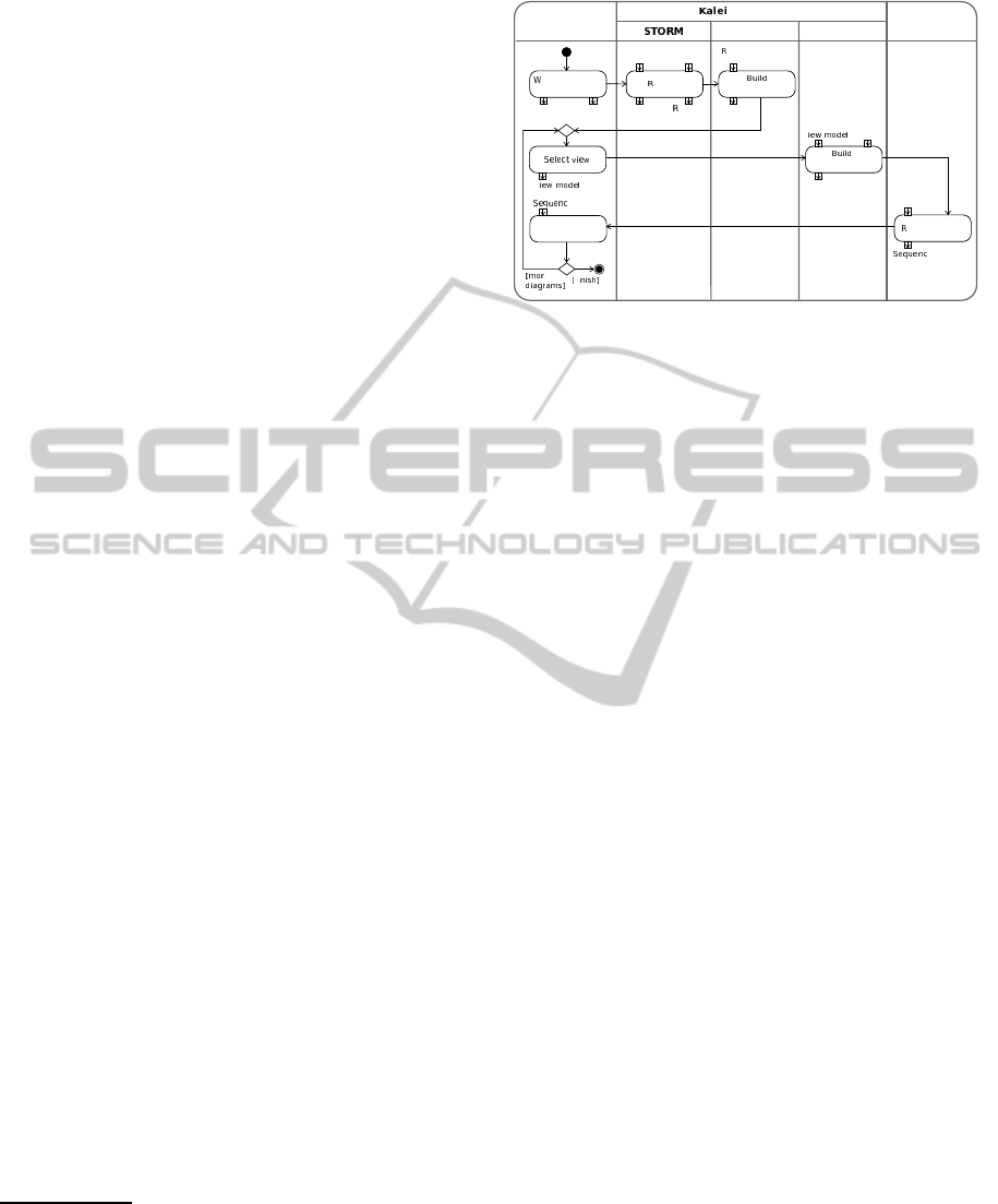
4 PROTOTYPE
IMPLEMENTATION
The KaleidoScope
7
tool can derive tailorable UML2
interaction models from scenario-based runtime tests.
Figure 13 depicts a high-level overview of the deriva-
tion procedure supported by KaleidoScope. The ar-
chitectural components of KaleidoScope (STORM,
trace provider, and model builder) as well as the di-
agram editor are represented via different swimlanes.
Artifacts required and resulting from each derivation
step are depicted as input and output pins of the re-
spective action.
6
The default value seq provides weak sequencing, i.e. or-
dering of fragments just along lifelines, which means that
occurrences on different lifelines from different operands
may come in any order (Object Management Group,
2011b).
7
Available for download from our website (Haendler,
2015).
Interaction model
System
e diagram
Scenario-test
Scenario-test
specificationSystem
Test log
untime
e diagram
Software
Engineer
doScope
un test
ender diagram
rite system and
scenario tests
interaction model
Analyse diagram
e
fi
trace model
Trace Provider
Model Builder
Diagram
Editor
data
untime
data
Trace
model
Interaction
specification
V
Trace
model
model
V
Figure 13: Process of deriving tailorable interaction models
with KaleidoScope.
4.1 Used Technologies
The “Scenario-based Testing of Object-oriented Run-
time Models” (STORM) test framework provides
an infrastructure for specifying and for executing
scenario-based component tests (Strembeck, 2011).
STORM provides all elements of our scenario-based
testing metamodel (see Fig. 3). KaleidoScope builds
on and instruments STORM to obtain execution-trace
data from running tests defined as STORM test suites.
This way, KaleidoScope keeps adoption barriers low
because existing STORM test specifications can be
reused without modification.
STORM is implemented using the dynamic
object-oriented language “Next Scripting Language”
(NX), an object-oriented extension of the “Tool Com-
mand Language” (Tcl). As KaleidoScope integrates
with STORM, we also implemented KaleidoScope
via NX/Tcl. In particular, we chose this develop-
ment environment because NX/Tcl provides numer-
ous advanced dynamic runtime introspection tech-
niques for collecting execution traces from scenario
tests. For example, NX/Tcl offers built-inmethod-call
introspection in terms of message interceptors (Zdun,
2003) and callstack introspection.
KaleidoScope records and processes execution
traces, as well as view configuration specifications, in
terms of EMF models (Eclipse Modeling Framework;
i.e. Ecore and MDT/UML2 models). More precisely,
the models are stored and handled in their Ecore/XMI
representation (XML Metadata Interchange specifica-
tion (Object Management Group, 2014a)). For trans-
forming our trace models into UML models, the re-
quired model transformations (Czarnecki and Helsen,
2003) are implemented via “Query View Transforma-
tions Operational” (QVTo) mappings (Object Man-
agement Group, 2011a). QVTo allows for implement-
ing concrete model transformations based on concep-
tual transformation in a straightforward manner.
4.2 Derivation Actions
Run Scenario Tests. For deriving interaction mod-
els via KaleidoScope, a newly created or an existing
scenario-test suite is executed by the STORM engine.
At this point, and from the perspective of the soft-
ware engineer, this derivation-enabled test execution
does not deviate from an ordinary one. The primary
objective of this test run is to obtain the runtime data
required to build a trace model. Relevant runtime data
consist of scenario-test traces (SUT feature calls and
their call dependencies), on the one hand, and struc-
tural elements of the scenario-test specifications (a
subset of STF feature calls and their call dependen-
cies), on the other hand.
Build Trace Model. Internally, the trace-provider
component of KaleidoScope instruments the STORM
engine before the actual test execution to record the
corresponding runtime data. This involves intercept-
ing each call of relevant features and deriving the cor-
responding call dependencies. At the same time, the
trace provider ascertains that its instrumentation re-
mains transparent to the STORM engine.
To achieve this, the trace provider instruments the
STORM engine and the tests under execution using
NX/Tcl introspection techniques. In NX/Tcl, method-
call introspection is supported via two variants of
message interceptors (Zdun, 2003): mixins and fil-
ters. Mixins (Zdun et al., 2007) can be used to dec-
orate entire components and objects. Thereby, they
intercept calls to methods which are known a priori.
In KaleidoScope, the trace provider registers a mixin
to intercept relevant feature calls on the STF, i.e. the
STORM engine. Filters (Neumann and Zdun, 1999)
are used by the trace provider to intercept calls to ob-
jects of the SUT which are not known beforehand.
To record relevant feature-call dependencies, the
trace provider uses the callstack introspection of-
fered by NX/Tcl. NX/Tcl offers access to its op-
eration callstack via special-purpose introspection
commands, e.g.
nx::current
, see (Neumann and
Sobernig, 2015). To collect structural data on the in-
tercepted STF and SUT instances, the trace provider
piggybacks onto the structural introspection facility
of NX/Tcl, e.g.,
info
methods, see (Neumann and
Sobernig, 2015). This way, structural data such as
class names, feature names, and relationships be-
tween classes can be requested.
The collected runtime data is then processed by
the trace provider. In particular, feature calls at the
application level are filtered to include only calls for
the scope of the SUT. This way, calls into other sys-
tem contexts (e.g., external componentsor lower-level
host language calls) are discarded. In addition, the
execution traces are reordered to report “invocations
interactions” first and “return interactions” second.
Moreover, the recorded SUT calls are linked to the
respective owning test blocks.
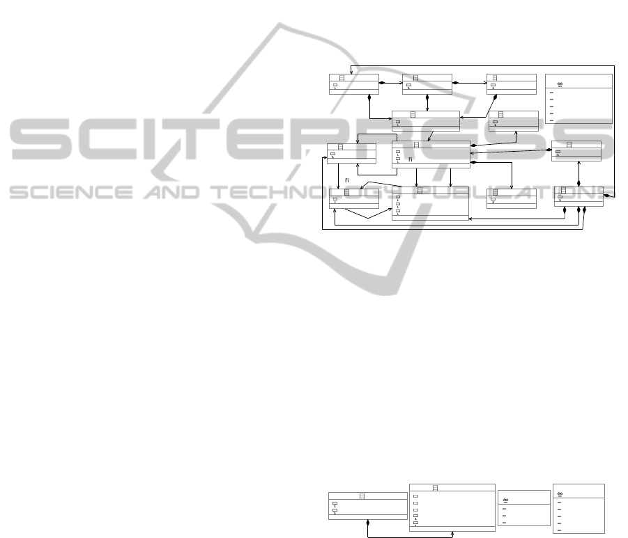
The processed runtime data is then stored as a
trace model which conforms to the
Trace
metamodel
defined via Ecore (see Fig. 14). This resulting trace
model comprises the relevant structural elements (test
suite, test case and test scenario), the SUT feature
calls and their call dependencies, each being linked
to a corresponding test block.
TraceModel
name : EString
FeatureCall
name : EString
de nedBySTF : EBoolean
Feature
name : EString
isConstructor : EBoolean
isDestructor : EBoolean
Instance
name : EString
Class
name : EString
Argument
name : EString
ReturnValue
name : EString
<<enumeration>>
TestBlockKind
setup
checkPreConditions
test
checkPostConditions
cleanup
TestScenario
name : EString
TestCase
name : EString
TestBlock
name : TestBlockKind
TestSuite
name : EString
Trace
name : EString
feature
0..*
class
0..*
instance
0..*
testSuite
1
trace
1
argument
0..*
returnValue
0..1
source
1
target
1
caller
1
callee
1
owningClass
1
de nition
1
ownedFeature
0..*
block
1..*
scenario
1..*
block
0..*
call
0..*
case
1..*
block
0..*
call
0..*
Figure 14: Trace metamodel, EMF Ecore.
Select Views. Based on the specifics of the test run
(e.g. whether an entire test suite or selected test cases
were executed) and the kind of runtime data collected,
different views are available to the software engineer
for selection. In KaleidoScope, the software engi-
neer can select a particular view by defining a view
model. This view model must conform to the
View
metamodelspecified using Ecore (see Fig. 15). Kalei-
doScope allows for defining views on the behavior of
the SUT by combining a selected call scope (SUT in-
ternal, STF to SUT, or both) and a selected test parti-
tion (entire test suite or a specific test case, scenario,
or block), as described in Section 3.
View
callScope : CallScopeKind
name : EString
TestPartition
testBlock : TestBlockKind
testScenario : EString
testCase : EString
isEntireTestSuite : EBoolean
name : EString
<<enumeration>>
CallScopeKind
stfToSut
sutIntern
<<enumeration>>
TestBlockKind
setup
preconditions
testbody
postconditions
cleanup
partition
1
both
Figure 15: View metamodel, EMF Ecore.
Build Interaction Model. The model-builder com-
ponent of KaleidoScope takes the previously created
pair of a trace model and a view model as input mod-
els for a collection of QVTo model transformations.
The output model of these QVTo transformations is
the UML interaction model. The conceptual map-
pings presented in Subsections 2.3 and 3.3 are imple-
mented in QVT Operational mappings (Object Man-
agement Group, 2011a), including the linking of rela-

tionships between the derived elements. In total, the
transformation file contains 24 mapping actions.
Display Sequence Diagrams. Displaying the derived
interaction models as sequence diagrams and present-
ing them to the software engineer is not handled by
KaleidoScope itself. As the derived interaction mod-
els are available in the XMI representation, they can
be imported by XMI-compliant diagram editors. In
our daily practice, we use Eclipse Papyrus (Eclipse
Foundation, 2015) for this task.
5 RELATED WORK
Closely related research can be roughly divided
into three groups: reverse-engineering sequence di-
agrams from system execution, techniques address-
ing the problem of model-size explosion in reverse-
engineered behavioral models and extracting trace-
ability links between test and system artifacts.
Reverse-engineering UML Sequence Diagrams.
Approaches applying dynamic analysis set the
broader context of our work (Oechsle and Schmitt,
2002; Briand et al., 2003; Guéhéneuc and Ziadi,
2005; Delamare et al., 2006). Of particular inter-
est are model-driven approaches which provide con-
ceptual mappings between runtime-data models and
UML interaction models.
Briand et al. (2003) as well as Cornelissen et
al. (2007) are exemplary for such model-driven ap-
proaches. In their approaches, UML sequence dia-
grams are derived from executing runtime tests. Both
describe metamodels to define sequence diagrams and
for capturing system execution in form of a trace
model. Briand et al. define mappings between these
two metamodels in terms of OCL consistency con-
straints. Each test execution relates to a single use-
case scenario defined by a system-level test case.
Their approaches differ from ours in some respects.
The authors build on generic trace metamodels while
we extend an existing scenario-test metamodel to
cover test-execution traces. Briand et al. do not pro-
vide for scoping the derived sequence diagrams based
on the executed tests unlike Cornelissen et al. (see be-
low). They, finally, do not capture the mappings be-
tween trace and sequence model in a formalized way.
Countering Model-size Explosion. A second group
of related approaches aims at addressing the prob-
lem of size explosion in reverse-engineered behav-
ioral models. Fernández-Sáez et al. (2015) conducted
a controlled experiment on the perceived effects of de-
rived UML sequence diagrams on maintaining a soft-
ware system. A key result is that derived sequence di-
agrams do not necessarily facilitate maintenance tasks
due to an excessive level of detail. Hamou-Lhadj
and Lethbridge (2004) and Bennett et al. (2008) sur-
veyed available techniques which can act as counter
measures against model-size explosion. The available
techniques fall into two categories: slicing and prun-
ing of components and calls as well as architecture-
level filtering.
Slicing (or sampling) is a way of reducing the re-
sulting model size by choosing a sample of execu-
tion traces. Sharp and Rountev (2005) propose in-
teractive slicing for zooming in on selected messages
and message chains. Grati et al. (2010) contribute
techniques for interactively highlighting selected ex-
ecution traces and for navigating through single ex-
ecution steps. Pruning (or hiding) provides abstrac-
tion by removing irrelevant details. For instance, Lo
and Maoz (2008) elaborate on filtering calls based
on different execution levels. In doing so, they pro-
vide hiding of calls based on the distinction between
triggers and effects of scenario executions. As an
early approach of architectural-level filtering, Rich-
ner and Ducasse (1999) provide for tailorable views
on object-oriented systems, e.g., by filtering calls be-
tween selected classes. In our approach, we adopt
these techniques for realizing different views conform
to a scenario-test viewpoint. In particular, slicing cor-
responds to including interactions of certain test parts
(e.g., test cases, test scenarios) only, selectively hiding
model elements to pulling from different feature-call
scopes (e.g., stimuli and internal calls). Architectural-
level filtering is applied by distinguishing elements by
their structural affiliation (e.g., SUT or STF).
Test-to-system Traceability. Another important
group of related work provides for creating traceabil-
ity links between test artifacts and system artifacts by
processing test-execution traces. Parizi et al. (2014)
give a systematic overview of such traceability tech-
niques. For instance, test cases are associated with
SUT elements based on the underlying call-trace data
for calculating metrics which reflect how each method
is tested (Kanstrén, 2008). Qusef et al. (2014)provide
traceability links between unit tests and classes under
test. These links are extracted from trace slices gen-
erated by assertion statements contained by the unit
tests. In general, these approaches do not necessar-
ily derive behavioral diagrams, however Parizi et al.
conclude by stating the need for visualizing traceabil-
ity links. These approaches relate to ours by inves-
tigating which SUT elements are covered by a spe-
cific part of the test specification. While they use
this information, e.g., for calculating coverage met-
rics, we aim at visualizing the interactions for doc-
umenting system behavior. However, Cornelissen et
al. (2007) pursue a similar goal by visualizing the

execution of unit tests. By leveraging the structure
of tests, they aim at improving the understandability
of reverse-engineered sequence diagrams (see above),
e.g., by representing the behavior of a particular stage
in a separate sequence diagram. While they share our
motivation for test-based partitioning, Cornelissen et
al. do not present a conceptual or a concrete solution
to this partitioning. Moreover, we leverage the test
structure for organizing the sequence diagram (e.g.,
by using combined fragments) and consider different
scopes of feature calls.
6 CONCLUSIONS
In this paper, we present an approach for deriving
tailorable UML interaction models for documenting
system behavior from scenario-based runtime tests.
Our approach allows for leveraging the structure of
scenario tests (i.e. test parts and call scope) to tai-
lor the derived interaction models, e.g., by pruning
details and by zooming in and out on selected de-
tails. This way, we also provide means to control
the size explosion in the resulting UML sequence dia-
grams. Our approach is model-drivenin the sense that
execution traces are represented through a dedicated
metamodel, mappings between this metamodel and
the UML metamodel are captured as inter-model con-
straint expressions (OCL), and model-to-model trans-
formations are used to turn model representations of
execution traces into UML interactions.
To demonstrate the feasibility of our approach,
we developed a prototype implementation (Kaleido-
Scope). Note, however, that our approach is applica-
ble for any software system having an object-oriented
design and implementation, provided that test suites
triggering inter-component interactions and a corre-
sponding test framework, which can be instrumented,
are available. In addition, the approach produces in-
teraction models conforming to the de facto standard
UML2.
In a next step, from a conceptual point of view,
we will incorporate complementary structural model
types, namely class models. This is particularly chal-
lenging as it requires abstraction techniques to extract
scenario-based views from the observed system struc-
ture. Besides, a prerequisite is the ability to com-
bine dynamic runtime introspection and static pro-
gram analysis. Moreover, this extension will require
additions to the scenario-test metamodel to model the
structure of the system under test.
From a practical angle, we will seek to apply the
approach on large-scale software projects. To com-
plete this step, our prototype tooling will have to be
extended to support runtime and program introspec-
tion for other object-oriented programming languages
and for the corresponding testing frameworks. More-
over, we plan to apply layout algorithms for automat-
ically rendering the derived interaction models as se-
quence diagrams.
REFERENCES
Bennett, C., Myers, D., Storey, M.-A., German, D. M.,
Ouellet, D., Salois, M., and Charland, P. (2008). A
survey and evaluation of tool features for understand-
ing reverse-engineered sequence diagrams. Softw.
Maint. Evol., 20(4):291–315.
Briand, L. C., Labiche, Y., and Miao, Y. (2003). Towards
the reverse engineering of UML sequence diagrams.
In Proc. WCRE’03, pages 57–66. IEEE.
Carroll, J. M. (2000). Five reasons for scenario-based de-
sign. Interact. Comput., 13(1):43–60.
Clements, P., Bachmann, F., Bass, L., Garlan, D., Ivers,
J., Little, R., Merson, P., Nord, R., and Stafford, J.
(2011). Documenting Software Architecture: Views
and Beyond. SEI. Addison-Wesley, 2nd edition.
Cornelissen, B., Van Deursen, A., Moonen, L., and Zaid-
man, A. (2007). Visualizing testsuites to aid in soft-
ware understanding. In Proc. CSMR’07, pages 213–
222. IEEE.
Czarnecki, K. and Helsen, S. (2003). Classification of
model transformation approaches. In WS Proc. OOP-
SLA’03, pages 1–17. ACM Press.
Delamare, R., Baudry, B., Le Traon, Y., et al. (2006).
Reverse-engineering of UML 2.0 sequence diagrams
from execution traces. In WS Proc. ECOOP’06.
Springer.
Eclipse Foundation (2015). Papyrus.
http://eclipse.org/papyrus/. Last accessed: 3 March
2015.
Falessi, D., Briand, L. C., Cantone, G., Capilla, R., and
Kruchten, P. (2013). The value of design rationale in-
formation. ACM Trans. Softw. Eng. Methodol., 22(3).
Fernández-Sáez, A. M., Genero, M., Chaudron, M. R.,
Caivano, D., and Ramos, I. (2015). Are forward
designed or reverse-engineered UML diagrams more
helpful for code maintenance?: A family of experi-
ments. Inform. Software Tech., 57(0):644 – 663.
Grati, H., Sahraoui, H., and Poulin, P. (2010). Extracting
sequence diagrams from execution traces using inter-
active visualization. In Proc. WCRE’10, pages 87–96.
IEEE.
Guéhéneuc, Y.-G. and Ziadi, T. (2005). Automated reverse-
engineering of UML v2.0 dynamic models. In WS
Proc. ECOOP’05. Springer.
Guerra, E., Lara, J., Kolovos, D. S., Paige, R. F., and San-
tos, O. M. (2013). Engineering model transformations
with transml. Softw. Syst. Model., 12(3):555–577.
Haendler, T. (2015). KaleidoScope. Institute for In-
formation Systems and New Media, WU Vienna.

http://nm.wu.ac.at/nm/haendler. Last accessed: 21
May 2015.
Hamou-Lhadj, A. and Lethbridge, T. C. (2004). A survey of
trace exploration tools and techniques. In Proc. CAS-
CON’04, pages 42–55. IBM Press.
Jacobson, I. (1992). Object-oriented software engineering:
A use case driven approach. ACM Press Series. ACM
Press.
Jarke, M., Bui, X. T., and Carroll, J. M. (1998). Scenario
management: An interdisciplinary approach. Require-
ments Eng., 3(3):155–173.
Kanstrén, T. (2008). Towards a deeper understanding of test
coverage. Softw. Maint. Evol., 20(1):59–76.
Lo, D. and Maoz, S. (2008). Mining scenario-based triggers
and effects. In Proc. ASE’08, pages 109–118. IEEE.
Nebut, C., Fleurey, F., Le Traon, Y., and Jezequel, J. (2006).
Automatic test generation: A use case driven ap-
proach. IEEE Trans. Softw. Eng., 32(3):140–155.
Neumann, G. and Sobernig, S. (2015). Next script-
ing framework. API reference. https://next-
scripting.org/xowiki/. Last accessed: 3 March
2015.
Neumann, G. and Zdun, U. (1999). Filters as a language
support for design patterns in object-oriented script-
ing languages. In Proc. COOTS’99, pages 1–14.
USENIX.
Object Management Group (2011a). Meta Object Facility
(MOF) 2.0 Query/View/Transformation Specification,
Version 1.1. http://www.omg.org/spec/QVT/1.1/. Last
accessed: 3 March 2015.
Object Management Group (2011b). Unified Model-
ing Language (UML), Superstructure, Version 2.5.0.
http://www.omg.org/spec/UML/2.4.1. Last accessed:
3 March 2015.
Object Management Group (2014a). MOF 2
XMI Mapping Specification, Version 2.4.2.
http://www.omg.org/spec/XMI/2.4.2/. Last accessed:
3 March 2015.
Object Management Group (2014b). Object
Constraint Language (OCL) - Version 2.4.
http://www.omg.org/spec/OCL/2.4/. Last accessed: 3
March 2015.
Oechsle, R. and Schmitt, T. (2002). JAVAVIS: Automatic
program visualization with object and sequence dia-
grams using the Java Debug Interface (JDI). In Proc.
Softw. Visualization, pages 176–190. Springer.
Parizi, R. M., Lee, S. P., and Dabbagh, M. (2014).
Achievements and challenges in state-of-the-art soft-
ware traceability between test and code artifacts.
Trans. Reliab. IEEE., pages 913–926.
Qusef, A., Bavota, G., Oliveto, R., De Lucia, A., and Bink-
ley, D. (2014). Recovering test-to-code traceability
using slicing and textual analysis. J. Syst. Softw.,
88:147–168.
Richner, T. and Ducasse, S. (1999). Recovering high-level
views of object-oriented applications from static and
dynamic information. In Proc. ICSM ’99, pages 13–
22. IEEE.
Ryser, J. and Glinz, M. (1999). A scenario-based approach
to validating and testing software systems using state-
charts. In Proc. ICSSEA’99.
Sharp, R. and Rountev, A. (2005). Interactive exploration
of UML sequence diagrams. In Proc. VISSOFT’05,
pages 1–6. IEEE.
Strembeck, M. (2011). Testing policy-based systems with
scenarios. In Proc. IASTED’11, pages 64–71. ACTA
Press.
Van Geet, J., Zaidman, A., Greevy, O., and Hamou-Lhadj,
A. (2006). A lightweight approach to determining
the adequacy of tests as documentation. In Proc.
PCODA’06, pages 21–26. IEEE CS.
Zdun, U. (2003). Patterns of tracing software structures and
dependencies. In Proc. EuroPLoP’03, pages 581–616.
Universitaetsverlag Konstanz 2004.
Zdun, U., Strembeck, M., and Neumann, G. (2007). Object-
based and class-based composition of transitive mix-
ins. Inform.Software Tech., 49(8):871–891.
Ziadi, T., Da Silva, M. A. A., Hillah, L.-M., and Ziane,
M. (2011). A fully dynamic approach to the reverse
engineering of UML sequence diagrams. In Proc.
ICECCS’11, pages 107–116. IEEE.
