
Model Checking to Improve Precision of Design Pattern Instances
Identification in OO Systems
Mario L. Bernardi
1
, Marta Cimitile
2
, Giuseppe De Ruvo
1
, Giuseppe A. Di Lucca
1
and Antonella Santone
1
1
Department of Engineering, University of Sannio, Benevento, Italy
2
Unitelma Sapienza University, Rome, Italy
Keywords:
Software Engineering, Design Patterns, Model Checking, Formal Methods, Models, Mining.
Abstract:
In the last two decades some methods and tools have been proposed to identify the Design Pattern (DP)
instances implemented in an existing Object Oriented (OO) software system. This allows to know which OO
components are involved in each DP instance. Such a knowledge is useful to better understand the system thus
reducing the effort to modify and evolve it. The results obtained by the existing methods and tools can suffer
a lack of completeness or precision due to the presence of false positive/negative. Model Checking (MC)
algorithms can be used to improve the precision of DP’s instances detected by a tool by automatically refining
the results it produces. In this paper a MC based technique is defined and applied to the results of an existing
DPs mining tool, called Design Pattern Finder (DPF), to improve the precision by verifying automatically the
DPs instances it detects. To verify and assess the feasibility and the effectiveness of the proposed technique,
we carried out a case study where it was applied on some open source OO systems. The results showed that
the proposed technique allowed to improve the precision of the DPs instances detected by the DPF tool.
1 INTRODUCTION
In the last two decades we have seen a growth on
the usage of Design Patterns (DPs) (Gamma et al.,
1995) in the development of Object Oriented (OO)
software systems, because their adoption contributes
to greatly improve the software quality (Ampatzoglou
et al., 2012), (Bergenti and Poggi, 2000). Unfortu-
nately, the lack of adequate documentation may make
difficult to understand which are the adopted Design
Patterns and where they are implemented (i.e., which
code components implement each instance of a DP)
in a system. Thus, several approaches have been pro-
posed to support the automatic identification of DPs
instances in an existing OO software system, linking
each detected instance to the OO components imple-
menting it (Peng et al., 2008), (Dong et al., 2007),
(Rasool and Streitfdert, 2011). The automatic detec-
tion of DPs provides software engineers the needed
knowledge to better comprehend the system reducing
the effort to modify and evolve it (Bergenti and Poggi,
2000), (Beyer, 2006), (L. Prechelt and Tichy, 2002).
However, the results obtained by the existing DP
detection approaches can suffer a lack of complete-
ness or precision due to the presence of false posi-
tive/negative. The precision of the DP’s instances de-
tected by a tool can be improved by Model Checking
(MC) techniques that can automatically refine the re-
sults the tool produces. Model checking has been ap-
plied to several fields. For instance, it has been used in
bioinfomatics to infer gene regulatory networks from
time series data (Ceccarelli et al., 2015) or to analyse
wiki quality (De Ruvo and Santone, 2015). In this pa-
per we exploit formal methods to automatically refine
the results produced by an existing DP mining tool; in
particular we employ Model Checking using the Lan-
guage of Temporal Ordering Specification (LOTOS)
and selective-µ-calculus (we interchangeably refer to
either µ or MU). The MC methodology aims to ana-
lyze the DPs’ instances, detected by the mining tool,
evaluating their correctness with respect to formally
encoded properties checked against the entire system
model represented with (basic) LOTOS. This allows
to reduce the number of wrongly detected patterns
(false positives) with respect to the original approach.
We apply the proposed MC technique to the De-
sign Pattern Finder (DPF) approach presented in
(Bernardi et al., 2013), (Bernardi et al., 2014). The
DPF approach is based on a meta-model and a Do-
main Specific Language (DSL) to represent both the
53
Bernardi M., Cimitile M., De Ruvo G., Di Lucca G. and Santone A..
Model Checking to Improve Precision of Design Pattern Instances Identification in OO Systems.
DOI: 10.5220/0005520500530063
In Proceedings of the 10th International Conference on Software Paradigm Trends (ICSOFT-PT-2015), pages 53-63
ISBN: 978-989-758-115-1
Copyright
c
2015 SCITEPRESS (Science and Technology Publications, Lda.)

software system and the searched DPs. The DPs mod-
els are organized as a hierarchy of declarative specifi-
cations and expressed as a wide set of high level prop-
erties that can be added, removed or relaxed obtaining
new pattern variants. Moreover, the DPF approach
with respect to the existing ones: i) allows to easily
specify variant forms of the classic DPs; ii) takes into
account a wider set of high level properties (includ-
ing also the behavioural properties to better character-
ize DPs) to specify a pattern. The DPF effectiveness,
was evaluated by applying it to several systems and
the obtained results are reported in (Bernardi et al.,
2014). Even if the obtained results are good, we ob-
served that the precision of the DPF can be further
improved. Indeed, DPF, as any other existing DPs
detecting approach, can suffer in lacking of precision
and completeness. We decided to apply the MC re-
finement to the DPF, because: (i) the authors of DPF
made available both the tool and the results of pre-
vious analysis they made; (ii) DPF seems to perform
better than other similar tools as shown in (Bernardi
et al., 2014); (iii) DPF is based on a meta-model that
can be exploited by the MC refinement to create (ba-
sic) LOTOS processes.
Therefore, we embodied a new refinement step
along the DPF detection process, where the DPF out-
comes are the inputs. From the DPF model we create
(basic) LOTOS processes and from DPF detected pat-
terns we generate selective-µ-calculus properties in
order to verify the actual existence of design patterns
instances through model checking.
The approach has been assessed by applying it
to some systems of open benchmarks proposed in
(Gu
´
eh
´
eneuc, 2007) and in (Rasool et al., 2010).
Of course, the proposed refining approach can be
extended to any other DP mining approach. The re-
mainder of this paper is organized as follows. Sec-
tion 2 discusses related work. Section 3 gives defini-
tions of basic LOTOS and selective-µ-calculus. Sec-
tion 4 presents and discusses the proposed detection
process, the implemented tools and their integration
aspects. Section 5 introduces and describes the case
study. Finally, in Section 6, conclusive remarks and
future work are presented.
2 RELATED WORK
In the last years, many design pattern recovery tech-
niques and tools have been proposed. In (Dong et al.,
2007) and (Rasool and Streitfdert, 2011) reviews re-
garding some of the main existing approaches can be
found.
Several approaches, as the ones in (Tsantalis et al.,
2006), (Dong et al., 2009), (Paakki et al., 2000), use
UML structures, represented as matrices, to model
structural and behavioral information of software sys-
tems. These techniques are applied to match a DP
template matrix with the matrix generated for the sys-
tem. In particular, a DP detection methodology based
on similarity scoring between graph vertexes is pro-
posed in (Tsantalis et al., 2006). The approach is able
to also recognize patterns that are slightly modified
from their standard representation. It exploits the fact
that patterns reside in one or more inheritance hier-
archies (in order to reduce the size of the graphs to
which the algorithm is applied). These approaches
are computationally efficient and have good precision
and recall rates. Their limit is that they miss to detect
patterns variants of similar design patterns. Further-
more, they are only limited to the patterns coded as
matrices and hence it is not suitable to be easily ex-
tended.
Some DP mining approaches are based on met-
ric techniques: program related metrics (i.e. general-
izations, aggregations, associations, interface hierar-
chies) are computed from different source code rep-
resentations and their values compared with source
code DP metrics (von Detten and Becker, 2011),
(Paakki et al., 2000), (Antoniol et al., 1998). These
techniques are computationally efficient because met-
ric computation is less expensive than structural pat-
tern recognition and do not require heuristic approach
to reduce search space through filtration (Gu
´
eh
´
eneuc
et al., 2010). Their precision and recall are usually
low; moreover they were experimented on few design
patterns in literature.
Other DP detection approaches exploit other tech-
niques (such as, fuzzy reasoning, bit vector compres-
sion, minimum key structure method, dynamic anal-
ysis using run-time execution traces, machine learn-
ing based approaches and concept analysis) that are
good as a complement to improve the DP detection
based on structural methods. For example, in (De Lu-
cia et al., 2009), De Lucia et. al. use a recovery tech-
nique based on the parsing of visual languages, and
supported by a visual environment automatically pro-
duced by a grammar based visual environment gen-
erator. A tool, using a mixed structural and metric
approach, for design pattern detection and software
architecture reconstruction is proposed in (Arcelli and
Zanoni, 2011).
Other studies (Dong et al., 2009), (Tonella et al.,
2007) have been focused on the formalization of em-
pirical evaluation criteria (Dong et al., 2009), (Tonella
et al., 2007).
There is few work, at best of our knowledge, that
exploits formal methods (model checking) based ap-
ICSOFT-PT2015-10thInternationalConferenceonSoftwareParadigmTrends
54

proaches to detect DP instances in existing OO sys-
tems. In (Taibi et al., 2009) formal framework to
specify the DPs at different levels of abstraction is
proposed. The framework uses stepwise refinement to
incrementally add details to a specification after start-
ing from the most abstract one. Moreover, a valida-
tion through model checking will verify that a specifi-
cation in a given level of abstraction is indeed a refine-
ment of a specification of a higher level. The limit of
this approach is that a domain specific language to de-
scribe DPs is missing and applications in real systems
has been never performed. In (Aranda and Moore,
2002), authors propose an approach aiming to vali-
date DPs using formal method. Similarly, in (Flores
et al., 2001) formal methods are used to demonstrate
that a particular design conforms to a given DPs. Both
these approaches, are not validated on real software
systems. Finally, in (De Lucia et al., 2010), a fully au-
tomated DPs mining approach performing both static
and dynamic analysis to verify the behavior of pattern
instances, is proposed. The static analysis exploits
model checking to analyze the interactions among ob-
jects, while the dynamic analysis of the pattern behav-
ior is performed through a code instrumentation and
monitoring phase, applied on the candidate pattern
instances. This approach, differently from ours, re-
quires the analysis of the collaboration among objects
at runtime by identifying and executing test cases on
the software system.
3 PRELIMINARIES
Historically, process algebras have been developed
as formal descriptions of complex computer systems,
and in particular of those involving communicating,
concurrently executing components. The crucial idea
in the definition of Process Algebras is the algebraic
structure of the concurrent processes. This uses a
state-based approach with labeled transitions, where
states and transitions correspond to processes and ac-
tions, respectively. There are many examples of pro-
cess algebras, like for example Milner’s Calculus of
Communicating Systems (CCS) (Milner, 1989) and
Language of Temporal Order Specification (LOTOS)
(Bolognesi and Brinksma, 1987), which we will use
in this paper.
3.1 Basic LOTOS
Let us now recall the main concepts of Basic LOTOS.
A Basic LOTOS program is defined as:
process ProcName := B
where E
endproc
where B is a behaviour expression, process
ProcName := B is a process declaration and E is a
process environment, i.e., a set of process declara-
tions. A behaviour expression is the composition, by
means of a set of operators, of a finite set A={i,a,b,
...} of atomic actions. Each occurrence of an action
in A represents an event of the system. An occurrence
of an action a ∈ A−{i} represents a communication
on the gate a. The action i does not correspond to a
communication and it is called the unobservable ac-
tion.
The syntax of behaviour expressions (also called pro-
cesses) is the following:
B ::= stop | a;B | B[]B| P | B|[S]|B |
B[f] | hide S in B | exit | B>>B | B[>B
where P ranges over a set of process names and a
ranges over A. The operational semantics of a be-
haviour expression B is a labelled transition system,
i.e., an automaton whose states correspond to be-
haviour expressions (the initial state corresponds to B)
and whose transitions (arcs) are labeled by actions in
A. The meaning of the operators composing behavior
expressions is the following:
• The action prefix a;B means that the correspond-
ing process executes the action a and then behaves
as B.
• The choice B1 [] B2 composes the two alterna-
tive behavior descriptions B1 and B2.
• The expression stop cannot perform any move.
• The parallel composition B1|[S]|B2, where S is
a subset of A −{i}, composes in parallel the two
behaviors B1 and B2. B1 and B2 interleave the ac-
tions not belonging to S, while they must synchro-
nize at each gate in S. A synchronization at gate a
is the simultaneous execution of an action a by
both partners and produces the single event a. If
S=
/
0 or S=A , the parallel composition means pure
interleaving or complete synchronization.
• Cyclic behaviors are expressed by recursive pro-
cess declarations.
• The relabeling B[f], where f: A → A is an ac-
tion relabeling function, renames the actions oc-
curring in the transition system of B as speci-
fied by the function f. This function is syntac-
tically defined as a0 -> b0,...,an->bn, mean-
ing f(a0)=b0,...,f(an)=bn, and f(a)=a for
each a not belonging to {a0,...,an}. Note that
each relabelling function has the property that
f(i) = i.
ModelCheckingtoImprovePrecisionofDesignPatternInstancesIdentificationinOOSystems
55

Table 1: Standard operational semantics of Basic LOTOS.
a ∈ A , l ∈ A − {i}
pre
a;B
a
−→
S
B
choice
B
1
a
−→
S
B
0
1
B
1
[] B
2
a
−→
S
B
0
1
inst
B
a
−→
S
B
0
P
a
−→
S
B
0
P := B ∈ E rel
B
a
−→
S
B
0
B[ f ]
f (a)
−→
S
B
0
[ f ]
par
B
1
a
−→
S
B
0
1
B
1
|[S]| B
2
a
−→
S
B
0
1
|[S]| B
2
a 6∈ S
com
B
1
a
−→
S
B
0
1
, B
2
a
−→
S
B
0
2
B
1
|[S]| B
2
a
−→
S
B
0
1
|[S]| B
0
2
a ∈ S
hide
1
B
a
−→
S
B
0
hide S in B
a
−→
S
hide S in B
0
a 6∈ S
hide
2
B
l
−→
S
B
0
hide S in B
i
−→
S
hide S in B
0
l ∈ S
• The hiding hide S in B renames the actions in
S, occurring in the transition system of B, with the
unobservable action i.
• The expression exit represents successful termi-
nation; it can be used by the enabling (B >> B)
and disabling (B[> B ) operators: B >> B rep-
resents sequentialization between B1 and B2 and
B[> B models interruptions. For the sake of sim-
plicity, we do not discuss these operators in the
paper.
Assume the precedence of the operators as speci-
fied by the following list, ordered in decreasing order:
; [f] hide |[S]| []
The semantics of a process B is precisely defined
by means of the structural operational semantics (in
Table 1). The semantic definition is given by a set
of conditional rules describing the transition relation
of the automaton corresponding to the behavior ex-
pression defining B. This automaton is called standard
transition system for B and is denoted by S (B). In
Table 1 the symmetrical rules for choice and parallel
composition are not shown.
We consider only finite Basic LOTOS programs,
i.e., programs with finite standard transition systems.
A sufficient condition for finiteness is that the parallel
operator does not occur inside recursive process dec-
larations. From now on, we write LOTOS instead of
Basic LOTOS.
3.2 Selective-µ-calculus
The selective-µ-calculus, introduced in (Barbuti et al.,
1999), is a branching temporal logic to express behav-
ioral properties of systems. It is equi-expressive to µ-
calculus (Stirling, 1989), but it differs from it in the
definition of the modal operators.
Given a set A of actions and a set Var of variables,
the selective-µ-calculus logic is the set of formulae
given by the following inductive definition:
• tt and ff are selective-µ-calculus formulae;
• Y , for all Y ∈ Var, is a selective-µ-calculus for-
mula;
• if ϕ
1
and ϕ
2
are selective-µ-calculus formulae
then ϕ
1
∧ ϕ
2
or ϕ
1
∨ ϕ
2
are selective-µ-calculus
formulae;
• if ϕ is a selective-µ-calculus formula then hKi
R
ϕ
and [K]
R
ϕ are selective-µ-calculus formulae,
where K,R ⊆ A ;
• if ϕ is a selective-µ-calculus formula then
µX.ϕ and νX.ϕ are selective-µ-calculus formulae,
where X ∈ Var.
The satisfaction of a formula ϕ by a state s of a tran-
sition system, written s |= ϕ, is defined as follows:
each state satisfies tt and no state satisfies ff; a
state satisfies ϕ
1
∨ ϕ
2
(ϕ
1
∧ ϕ
2
) if it satisfies ϕ
1
or
(and) ϕ
2
. [K]
R
ϕ and hKi
R
ϕ are the selective modal
operators:
ICSOFT-PT2015-10thInternationalConferenceonSoftwareParadigmTrends
56
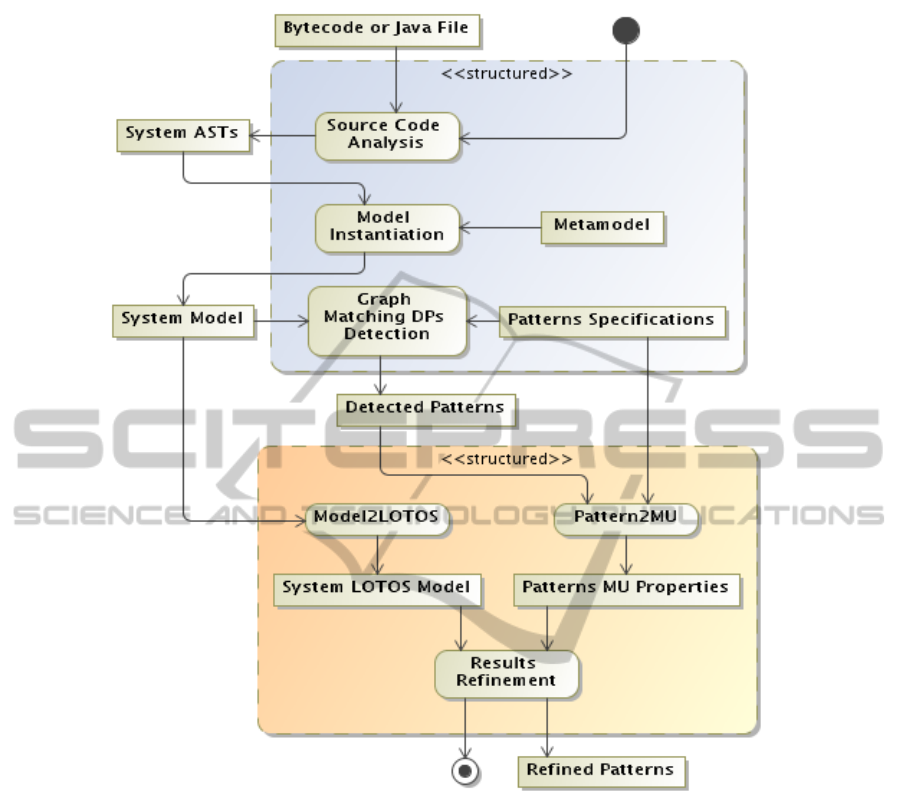
Figure 1: The DPs mining process represented as a UML activity diagram.
[K]
R
ϕ is satisfied by a state which, for every per-
formance of a sequence of actions not be-
longing to R ∪ K, followed by an action in
K, evolves to a state obeying ϕ.
hKi
R
ϕ is satisfied by a state which can evolve to a
state obeying ϕ by performing a sequence
of actions not belonging to R ∪ K, followed
by an action in K.
The selective modal operators hKi
R
ϕ and [K]
R
ϕ sub-
stitute the standard modal operators hKi ϕ and [K] ϕ.
The basic characteristic of the selective-µ-calculus is
that each formula allows us to immediately point out
the parts of the transition system that do not alter the
truth value of the formula itself. More precisely, the
only actions relevant for checking a formula are the
ones explicitly mentioned by the selective modal op-
erators used in the formula itself. Thus, the result of
checking the formula is independent from all other
actions. This information can be exploited to obtain
reduced transition systems on which the formula can
be equivalently checked (see, for example, (Barbuti
et al., 2005)). The precise definition of the satisfac-
tion of a closed formula ϕ by a state of a transition
system can be found in (Barbuti et al., 1999).
4 THE APPROACH
In this section we introduce the overall Design Pattern
mining approach.
The process is structured in two main sub-
processes. The first one, shown in the upper part of
the Figure 1, performs the design pattern detection
applying the Graph-Matching approach implemented
by DPF, discussed in (Bernardi et al., 2014). The sec-
ModelCheckingtoImprovePrecisionofDesignPatternInstancesIdentificationinOOSystems
57
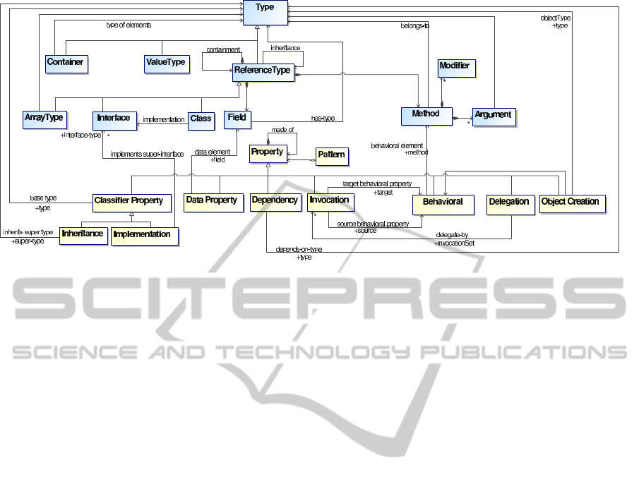
Figure 2: The meta-model represented as a UML class diagram.
ond sub-process, depicted in the lower part of the fig-
ure, performs the refinement of DPF results using the
model checking approach proposed in this paper.
In the following there is a short description of each
process activity, while next sub-sections will provide
more details about them:
• Source Code Analysis — The source and byte-
codes of the system under study are parsed and
the complete ASTs of the system are produced.
• Model Instantiation — A traversal of the system
AST is performed to generate an instance of the
system model (i.e. the system graph S), conform-
ing to the meta-model defined for DPF. Rapid type
analysis (RTA), class flattening and inlining of not
public methods are exploited in order to build a
system’s representation suitable for the matching
algorithm.
• Graph-Matching DPs Detection — The DPF
graph matching algorithm, described in (Bernardi
et al., 2014), is performed to match the system
model, built in the previous step, with the pattern
specifications graphs of the DPs to be detected.
• Pattern2MU — Each pattern specification to
be detected is written as a set of templated µ-
properties. These properties involve the patterns
roles and their relationships. The template param-
eters are bound to the concrete system elements
using information extracted from the pattern in-
stances found in the detection step (i.e. roles and
the system elements related to them).
• Model2LOTOS — In order to check if a given
set of parametrized µ-properties holds, the sys-
tem model graph should be expressed in a suitable
model (in our approach LOTOS was exploited).
Hence this step takes the system model graph as
input and translates it to a LOTOS model instance.
This translation has to be performed only one time
for each system to be mined.
• Results refinement — This step checks the
parametrized sets of µ-properties obtained from
the pattern specifications catalogue against the
LOTOS model of the system in order to reduce
the number of false positives.
4.1 Graph-matching DPs Detection
The detection of the DPs instances is performed ac-
cording to the DPF approach (Bernardi et al., 2014).
The DPF approach is based on a meta-model and a
Domain Specific Language (DSL) to model the struc-
ture of both OO systems and DPs. The meta-model
uniformly describes the DPs and systems in terms
of relationships among code elements, and allows to
trace down to the DPs Properties and Types compo-
nents both the structural and behavioral relationships
among the types. The meta-model is reported in Fig-
ure 2 as a UML class diagram. The upper part of the
figure shows the structure of an OO system as a set
of Types (i.e., Container, Value, Reference, and Com-
pound Types) along with their relationships. Refer-
ence Types, composed by Fields and Methods can in-
herit from another ReferenceType as well as can con-
tain another ReferenceType. Similarly, in the bottom
part of the figure a DP is modeled as the aggregation
of several Properties (Classifier, Behavioral, Depen-
dency, Invocation, Delegation, Object Creation). The
meta-model is exploited to define the DSL to repre-
sent structural and behavioral relevant properties of
OO software systems, as well as to express the spec-
ifications of the DPs to be detected. Each pattern, in
order to be detected, has been modeled writing a DSL
ICSOFT-PT2015-10thInternationalConferenceonSoftwareParadigmTrends
58

p a t t e r n S i n g l e t o n {
f i n a l ty p e X {
X has p r i v a t e c o n s t r u c t o r c ;
X has f i e l d f o f t y p e X;
X has p u b l i c s t a t i c methods−s e t c r e a t i o n H o o k s
each { d e p e n d s on f ; }
}
}
Figure 3: The DSL of Singleton DP.
pattern specification stored into a repository. The cur-
rent repository stores a catalog composed of 18 pat-
terns with 56 variants. Each DSL specification can
be translated into a graph, called DP Graph (DPG), in
which elements are nodes and properties are labeled
edges. The DPG is part of the input for the graph-
matching detection algorithm. As an example of how
a pattern is modeled by the DSL and represented by
the corresponding DP Graph , let us consider a classic
Singleton DP as defined in (Gamma et al., 1995). The
DSL, reported in Figure 3, provides a Singleton def-
inition implemented with a final class, a private con-
structor and a public static getter method. To mine
multiple instance getters, the variant defines a method
set called “creationHooks” (the box labelled by cH in
Figure 4). Each method in this set requires a depen-
dency on the static Singleton field “f”.
Along the execution of the DPF Graph Matching
algorithm, the system graph (i.e., the instance of the
system model) is traversed and each pattern instance
sub-graph is mapped to the corresponding matching
DPG (to identify the actually implemented patterns).
More insights and details about the DPF approach can
be found in (Bernardi et al., 2014).
4.2 DPF Refinement
The proposed approach is based on the use of formal
methods. From the DPF outcomes we derive LO-
TOS processes, which are successively used to per-
form model checking. The goal of the approach is to
Figure 4: GoF Singleton DP graph.
increase the precision of DPs mining results produced
by DPF. This part of the approach is addressed by the
second sub-process shown in the bottom of Figure 1
which comprises the following steps:
1. LOTOS System model creation (Model2LOTOS
activity)
2. Pattern Property generation (Pattern2MU activity)
3. Pattern Matching through Model Checking (Re-
sults Refinement activity)
In the following subsections the three steps are
discussed by more details.
4.2.1 LOTOS Model Creation
We use, as internal representation, the LOTOS lan-
guage. Thus, LOTOS specifications are generated
starting from the internal representation of DPF. This
is obtained by defining a DPF-to-LOTOS transform
operator T . The function T directly applies to Java
system outcomes of DPF and translates them into LO-
TOS process specifications. The function T is defined
for each part of a Java system such as classes, inter-
faces, methods, fields. Each one has been translated
into LOTOS processes. First of all, a System is com-
posed of a set of Types. A Type may be a ClassType
or an InterfaceType. A ClassType is made up of Meth-
ods. Types may be tied by inheritance relations and a
ClassType may implement an InterfaceType, as usu-
ally occurs in OO software systems.
System
The generic Java System containing k types is trans-
lated into the following LOTOS process:
T (C) = process SY ST EM :=
Type
1
[]···[]Type
k
end proc
where Type
i
is written using the fully qualified Java
name. The LOTOS process SY ST EM represents the
parent process of all the types. Each translated LO-
TOS model has a System process.
Type
As stated, a Type may be a ClassType or an Interface-
Type. If FQN is the fully qualified name of a Type,
a ClassType is translated into the following LOTOS
process:
ModelCheckingtoImprovePrecisionofDesignPatternInstancesIdentificationinOOSystems
59

T (T ) = process
FQN ClassType := name ClassType;
(FQN Method
i
;FQN Method
i
Method[] · · · []
FQN Method
k
;FQN Method
k
Method[]
implements; (FQN Inter f aceType
j
[]···[]
FQN Inter f aceType
w
)[]
inherits; (FQN ClassType
l
[]···[]
FQN ClassType
y
)[] f ield.(FQN Inter f aceType
h
[]
···[]FQN ClassType
z
))
end proc
Instead, an InterfaceType is translated into the fol-
lowing LOTOS process:
T (I) = process
FQN Inter f aceType :=
name Inter f aceType; (FQN Method
i
;
FQN Method
i
Method[] · · · []
FQN Method
k
;FQN Method
k
Method[]
inherits; (FQN Inter f aceType
l
[]···[]
FQN Inter f aceType
y
))
end proc
where implements and inherits are actions which
respectevely indicate implementation of interfaces
and inheritance relation between types.
Method
A method is represented with its own arguments and
with a modifier, thus it is translated into the following
LOTOS process:
T (M) = process
FQN Method := name Method;
(arg
i
[]···[]arg
k
[]modi f ier mod)
end proc
where arg
i
is the name of the argument and mod is
the type of modifier such as public, private, protected.
4.2.2 Pattern Property Generation
After the LOTOS processes of the Java software sys-
tem are generated, we can use selective-µ-calculus
logic to specify desired properties. A pattern is trans-
lated into a selective-µ-calculus property. Each design
pattern leads to a different property, although a set of
common properties are used as building blocks:
1. Existence of Interface Implementation:
himplementsi
/
0
hname Inter f aceTypei
/
0
tt
2. Existence of Inheritance:
hinheritsi
/
0
hname ClassTypei
/
0
tt ∧
hinheritsi
/
0
hname Inter f aceTypei
/
0
tt
3. Existence of a Method:
hname Methodi
/
0
tt
4. Existence of a Field:
h f ieldi
/
0
hname Inter f aceTypei
/
0
tt ∧
h f ieldi
/
0
hname ClassTypei
/
0
tt
5. Existence of an Argument:
hargi
/
0
hname Inter f aceTypei
/
0
tt ∧
hargi
/
0
hname ClassTypei
/
0
tt
4.2.3 Pattern Matching through Model
Checking
Once we have created the LOTOS model of a Java
software system and we also have built all the proper-
ties which represent the design patterns, we can pro-
ceed with model checking. As aforementioned, in this
paper both model and properties (patterns) come out
translating the ones of DPF. Such translations have
been completely automated.
One of the most popular toolbox for the design
of asynchronous concurrent systems is CADP (Gar-
avel et al., 2013). It supports high-level descriptions
written in various languages, mainly LOTOS. In the
CADP the verification of temporal logic formulae is
based on model checking (Clarke et al., 2001), a for-
mal technique for proving the correctness of a system
with respect to a desired behavior. This is accom-
plished by checking whether a structure represent-
ing the system (typically a labelled transition system)
satisfies a temporal logic formula describing the ex-
pected behaviour.
The CADP model checker is applied verifying
each pattern against the System model. When the re-
sult is TRUE, it means that the pattern has been found,
FALSE otherwise. Thanks to a very detailed LOTOS
model we are able to identify false positives among
the DPs detected by DPF. Eventually, we have all the
necessary information to improve the precision of the
overall results, as explained in the following section.
5 CASE STUDY
The effectiveness and efficiency of the proposed ap-
proach has been validated applying it to some middle-
sized OO systems. These systems were available
from the publicly available benchmarks proposed in
(Gu
´
eh
´
eneuc, 2007) and in (Rasool et al., 2010).
Due to space constraints we only present the re-
sults for the two systems reported in Table 2 and the 4
ICSOFT-PT2015-10thInternationalConferenceonSoftwareParadigmTrends
60

Table 2: Analyzed systems characteristics.
System
Name
Version Size
(KLOC)
#Types #Methods
JHotDraw 5.1 8,9K 174 1316
QuickUML 2.1 9,2K 230 1082
Table 3: Results obtained on JHotDraw and QuickUML.
Step → Detection Refinement
↓Design Pattern GS D T
P
F
P
F
N
P R D T
P
F
P
F
N
P R
System→ JHotDraw
Composite/spec{GoF} 16 19 14 5 2 0,74 0,88 17 14 3 2 0,82 0,88
Factory Method/spec{Parametrized} 15 14 12 2 3 0,86 0,8 14 12 2 3 0,86 0,8
System→ QuickUML
Command/spec{GoF} 10 8 7 1 3 0,88 0,7 8 8 0 1 1 0,89
Strategy/spec{GoF} 15 18 12 6 3 0,67 0,8 12 12 0 3 1 0,8
GoF patterns (Command, Composite, Factory meth-
ods and Strategy) for which the DPF method provides
the lowest precision.
According to (Pettersson et al., 2010), in order
to assess effectiveness and correctness of the pro-
posed approach, we evaluated precision and recall. To
compute recall and precision we assume that a pat-
tern instance can be classified into one of four cate-
gories (T
P
: true positive, F
P
: false positive, T
N
: true-
negative, and F
N
false-negative).
Precision is defined as the ratio of correctly
found occurrences to occurrences provided by the
tool whereas recall is defined as the ratio of correctly
found occurrences to all correct occurrences:
Precision = T
P
/(T
P
+ F
P
) (1)
Recall = T
P
/(T
P
+ F
N
) (2)
To verify the correctness of the results we con-
sidered as Gold Standard (GS) the union of both the
benchmarks cited in (Gu
´
eh
´
eneuc, 2007) and in (Ra-
sool et al., 2010) (assumed to be correct) with the
correct results produced by DPF approach (i.e., also
the instances not present in the benchmarcks, mainly
due to DP variants, but correctly detected by DPF as
verified by manual code inspection).
1
Since in this context we are interested to assess the
improvement in precision obtained after the model-
checking driven refinement, we evaluate and compare
precision and recall at the end of both DPs Matching
and DPF Refinement steps.
Table 3 reports, for each of the analyzed systems:
the name of the DPs searched in the code (first col-
umn), the number of true positive instances as pro-
1
Of course, the different formats of the benchmarks were
translated into a unique common format to store the con-
sidered GS.
vided by the benchmark (GS), and two groups of
columns for the DPs detection performed by DPF and
the DPF refinement steps performed using the model
checker. Each group contains the number of detected
patterns (column D), the number of true positive (col-
umn Tp), the number of false positive and negative
ones (columns F
p
and F
n
). The last two columns re-
port respectively precision (P) and recall (R).
In the Composite-GoF pattern, for the JHotDraw
system, the model-checking step reduced the number
of false positive from five to three raising the preci-
sion from 0.74 to 0.82. Looking at the three remaining
false positive we can see that these are cases in which
the assignment of the element to a role in the pattern
can be only done looking at the semantics of the el-
ement. This is confirmed by the presence in the re-
sults of two methods of 3 concrete composite classes
(read() and readObject() in subclasses of Compos-
iteFigure) that were mistakenly bound to Operation
role by both the steps but are not part of the inter-
face. This is also the case for the parametrized Fac-
tory Method for which the two false positives have the
same structure and behaviour of the defined property
but cannot be considered as factory methods (decom-
pose(. . . ) and flip(. . . ) method of Figure class).
In QuickUML system in both cases properties
were able to consider structural or behavioral rela-
tionships that the original approach was unable to
take into account. For instance, for the Strategy
pattern several false positive (e.g. the ToolPalette,
Clipboard Tool, PropertyChangeHandler and Selec-
tioModel contexts) were detected since the properties
were able to better identify indirect relationships and
type nesting relationships.
The overall average improvement for all the con-
sidered patterns and systems was above 19%.
ModelCheckingtoImprovePrecisionofDesignPatternInstancesIdentificationinOOSystems
61

6 CONCLUSIONS AND FUTURE
WORKS
In this work we exploit formal methods to automat-
ically refine the results produced by an existing DP
mining approach, in particular we selected the DPF
approach. DPF approach introduces a meta-model
to represent both the patterns and the system under
study as graphs in order to apply a graph match-
ing algorithm. In this paper the detection process
is enriched with a model-checking refinement step
in which the system model is represented using LO-
TOS and patterns as selective-µ-calculus properties
checked against it. The defined LOTOS model al-
lows to check a wider set of properties that lead to
a reduction of the number of false positives. The per-
formed experiments confirmed the feasibility, correct-
ness, and effectiveness of the approach showing, on
the analyzed systems, an improvement of the preci-
sion (19% on average) with a very reduced impact on
the original recall. As future work, a more complete
translation of pattern specifications to selective-µ-
calculus properties will be defined. Moreover, we will
perform the translation of the entire DP catalog de-
fined in (Bernardi et al., 2014) as selective-µ-calculus
properties allowing the experimentation on the com-
plete benchmark comprised of 12 OO systems. Fi-
nally, we want to assist software engineers providing
WYSIWYG tools that support our approach as done
in (De Ruvo and Santone, 2014).
REFERENCES
Ampatzoglou, A., Frantzeskou, G., and Stamelos, I. (2012).
A methodology to assess the impact of design patterns
on software quality. Inf. Softw. Technol., 54(4):331–
346.
Antoniol, G., Fiutem, R., and Cristoforetti, L. (1998). De-
sign pattern recovery in object-oriented software. In
Proceedings of the 6th International Workshop on
Program Comprehension, IWPC ’98, pages 153–,
Washington, DC, USA. IEEE Computer Society.
Aranda, G. and Moore, R. (2002). A formal model for
verifying compound design patterns. In Proceedings
of the 14th International Conference on Software En-
gineering and Knowledge Engineering, SEKE ’02,
pages 213–214, New York, NY, USA. ACM.
Arcelli, F. and Zanoni, M. (2011). A tool for design pat-
tern detection and software architecture reconstruc-
tion. Inf. Sci., 181(7):1306–1324.
Barbuti, R., De Francesco, N., Santone, A., and Vaglini,
G. (1999). Selective mu-calculus and formula-based
equivalence of transition systems. J. Comput. Syst.
Sci., 59(3):537–556.
Barbuti, R., De Francesco, N., Santone, A., and Vaglini, G.
(2005). Reduced models for efficient ccs verification.
Formal Methods in System Design, 26(3):319–350.
Bergenti, F. and Poggi, A. (2000). Improving uml designs
using automatic design pattern detection. In Proc.
12th. International Conference on Software Engineer-
ing and Knowledge Engineering (SEKE 2000, pages
336–343.
Bernardi, M., Cimitile, M., and Di Lucca, G. (2013).
A model-driven graph-matching approach for design
pattern detection. In 20th Working Conference on Re-
verse Engineering (WCRE), pages 172–181.
Bernardi, M., Cimitile, M., and Di Lucca, G. (2014).
Design patterns detection using a dsl-driven graph
matching approach. Journal of Software: Evo-
lution and Process, Published online in Wi-
ley Online Library (wileyonlinelibrary.com). DOI:
10.1002/smr.1674.
Beyer, D. (2006). Relational programming with crocopat.
In Proceedings of the 28th international conference on
Software engineering, ICSE ’06, pages 807–810, New
York, NY, USA. ACM.
Bolognesi, T. and Brinksma, E. (1987). Introduction to the
iso specification language lotos. Computer Networks,
14:25–59.
Ceccarelli, M., Cerulo, L., De Ruvo, G., Nardone, V., and
Santone, A. (2015). Infer gene regulatory networks
from time series data with probabilistic model check-
ing. FormaliSE 2015.
Clarke, E. M., Grumberg, O., and Peled, D. (2001). Model
checking. MIT Press.
De Lucia, A., Deufemia, V., Gravino, C., and Risi, M.
(2009). Design pattern recovery through visual lan-
guage parsing and source code analysis. Journal of
Systems and Software, 82(7):1177 – 1193.
De Lucia, A., Deufemia, V., Gravino, C., and Risi, M.
(2010). Improving behavioral design pattern detec-
tion through model checking. In Software Mainte-
nance and Reengineering (CSMR), 2010 14th Euro-
pean Conference on, pages 176–185.
De Ruvo, G. and Santone, A. (2014). An eclipse-based ed-
itor to support lotos newcomers. In Enabling Tech-
nologies: Infrastructure for Collaborative Enterprises
(WETICE), 2014 IEEE 23rd International Conference
on.
De Ruvo, G. and Santone, A. (2015). Analysing wiki
quality using probabilistic model checking. In 2015
IEEE 24th International WETICE Conference, WET-
ICE 2015, Larnaca, Cyprus, 15-17 June, 2015.
Dong, J., Zhao, Y., and Peng, T. (2007). Architecture
and design pattern discovery techniques - a review.
In Arabnia, H. R. and Reza, H., editors, Software
Engineering Research and Practice, pages 621–627.
CSREA Press.
Dong, J., Zhao, Y., and Sun, Y. (2009). A matrix-based
approach to recovering design patterns. Trans. Sys.
Man Cyber. Part A, 39(6):1271–1282.
Flores, A., Moore, R., and Reynoso, L. (2001). A formal
model of object-oriented design and gof design pat-
terns. In Proceedings of the International Symposium
ICSOFT-PT2015-10thInternationalConferenceonSoftwareParadigmTrends
62

of Formal Methods Europe on Formal Methods for In-
creasing Software Productivity, FME ’01, pages 223–
241, London, UK, UK. Springer-Verlag.
Gamma, E., Helm, R., Johnson, R., and Vlissides, J. (1995).
Design patterns: elements of reusable object-oriented
software. Addison-Wesley Longman Publishing Co.,
Inc., Boston, MA, USA.
Garavel, H., Lang, F., Mateescu, R., and Serwe, W. (2013).
CADP 2011: a toolbox for the construction and anal-
ysis of distributed processes. STTT, 15(2):89–107.
Gu
´
eh
´
eneuc, Y. G. (http://www.ptidej.net/tool/design
patterns/, 2007). P-mart: Pattern-like micro architec-
ture repository,. In Proceedings of the 1st EuroPLoP
Focus Group on Pattern Repositories. Michael , Ali-
aksandr Birukou, and Paolo Giorgini.
Gu
´
eh
´
eneuc, Y. G., Guyomarc’H, J. Y., and Sahraoui, H.
(2010). Improving design-pattern identification: a
new approach and an exploratory study. Software
Quality Control, 18(1):145–174.
L. Prechelt, B. Unger-Lamprecht, M. P. and Tichy, W.
(2002). Two controlled experiments assessing the use-
fulness of design pattern documentation in program
maintenance. IEEE Trans. Softw. Eng., 28(6):595–
606.
Milner, R. (1989). Communication and concurrency. PHI
Series in computer science. Prentice Hall.
Paakki, J., Karhinen, A., Gustafsson, J., Nenonen, L., and
Verkamo, A. I. (2000). Software metrics by archi-
tectural pattern mining. In Proceedings of the Inter-
national Conference on Software: Theory and Prac-
tice (16th IFIP World Computer Congress, pages 325–
332.
Peng, T., Dong, J., and Zhao, Y. (2008). Verifying be-
havioral correctness of design pattern implementation.
In Proceedings of the Twentieth International Con-
ference on Software Engineering & Knowledge Engi-
neering (SEKE’2008), pages 454–459.
Pettersson, N., Lowe, W., and Nivre, J. (2010). Evalua-
tion of accuracy in design pattern occurrence detec-
tion. IEEE Trans. Softw. Eng., 36(4):575–590.
Rasool, G., Philippow, I., and M
¨
ader, P. (2010). Design
pattern recovery based on annotations. Advances in
Engineering Software, 41(4):519 – 526.
Rasool, G. and Streitfdert, D. (2011). A survey on design
pattern recovery techniques. IJCSI International Jour-
nal of Computer Science Issues, 8(2):251 – 260.
Stirling, C. (1989). An introduction to modal and temporal
logics for ccs. In Concurrency: Theory, Language,
And Architecture, pages 2–20.
Taibi, T., Herranz-Nieva,
´
A., and Moreno-Navarro, J. J.
(2009). Stepwise refinement validation of design
patterns formalized in TLA+ using the TLC model
checker. Journal of Object Technology, 8(2):137–161.
Tonella, P., Torchiano, M., Du Bois, B., and Syst
¨
a, T.
(2007). Empirical studies in reverse engineering: state
of the art and future trends. Empirical Softw. Engg.,
12(5):551–571.
Tsantalis, N., Chatzigeorgiou, A., Stephanides, G., and
Halkidis, S. T. (2006). Design pattern detection us-
ing similarity scoring. IEEE Trans. Softw. Eng.,
32(11):896–909.
von Detten, M. and Becker, S. (2011). Combining clus-
tering and pattern detection for the reengineering of
component-based software systems. In Proceedings
of the joint ACM SIGSOFT conference QoSA-ISARCS,
QoSA-ISARCS ’11, pages 23–32, New York, NY,
USA. ACM.
ModelCheckingtoImprovePrecisionofDesignPatternInstancesIdentificationinOOSystems
63
