
New Approach to the Artificial Force Concept for Skid-steering Mobile
Platform
∗
Alicja Mazur, Wojciech Domski, Mirela Kaczmarek and Mateusz Cholewi´nski
Chair of Cybernetics and Robotics, Electronics Faculty, Wrocław University of Technology,
ul. Janiszewskiego 11/17, 50-372 Wrocław, Poland
Keywords:
Skid-steering Mobile Platform, Nonholonomic Constraints, Artificial Force.
Abstract:
In the paper control algorithm for skid-steering mobile platform is presented. For mathematical model of such
an object, expressed in auxiliary coordinates, control law based on the idea of artificial force is introduced.
A skid-steering mobile platform is an underactuated control system with a rectangular input matrix. In the
approach explored in the paper it was assumed that there exists an additional control input, giving an additional
column in input matrix and causing this matrix invertible. Because such an actuator does not exist in reality,
this input was kept equal to zero equivalently. Simulations have proved proper work of this method.
1 INTRODUCTION
Wheeled mobile platforms can be treated as indepen-
dent robots or as a transportation part of complex
robotic systems. Depending on wheels’ type and a
way in which they are fixed to the chassis, motion
of wheeled mobile platforms can be realized with or
without slipping effect. If slippage effect between
wheels and surface does not occur, then exists an
equation describing forbidden directions for realized
velocities of the system. Such an equation is called
nonholonomic constraint in platform’s motion.
A special kind of wheeled mobile platforms are
platforms with tracks. They can be modeled by a
chassis with more than one axis equipped with fixed
wheels. These platforms are called skid-steering mo-
bile platforms (SSMP), due to skidding effect obse-
rved in their behavior.
Designing of a control algorithm for the skid-
steering platform is based on a proper mathematical
model of a considered object. A problem occurs in
this point, namely there is not an adequate model of
objects moving with sleeping effects. There were
some attempts to get strict model of wheeled mo-
bile platforms using slow manifold idea (Campion
and Motte, 2000) or singular perturbation approach
(D’Andrea-Novel et al., 2007). Unfortunately, math-
∗
The works of Alicja Mazur, Wojciech Domski and
Mirela Kaczmarek were supported by the Wrocław Univer-
sity of Technology under the statutory grant S40173 and the
work of Mateusz Cholewi´nski under the grant B40235.
ematical models presented in literature are inadequate
because they don’t cover both cases, i.e. motion with
or without slippage effect. For this reason authors de-
scribing slippage phenomena in skid-steering mobile
platforms use only approximate models with artifi-
cial constraints see e.g. (Caracciolo et al., 1999) or
with artificial forces (Mazur et al., 2013), (Mazur and
Cholewi´nski, 2013).
In papers treating of skid-steering mobile plat-
forms, another approach to the problem of object
modeling has appeared. In (Pazderski and Kozłowski,
2008) authors observed that an artificial constraint in-
troduced by Caracciolo et al. is inadequate to real
behavior of SSMP platform and proposed modifica-
tion of such a constraint to modified form. It implied
nonholonomicconstraint of second order i.e. dynami-
cally constrained model of SSMP platform. The same
idea can be found in (Mohammadpour et al., 2010)
and in (Maalouf et al., 2006).
In this paper a new method of modeling SSMP
platform is used as a base for artificial force con-
cept. In previous works, e.g. (Mazur et al., 2013) and
(Mazur and Cholewi´nski, 2013), SSMP platform with
four wheels was modeled as a chassis with two axes
of fixed wheels coupled on both sides of platform. In
this case it was impossible to obtain independent mo-
tion of each wheel separately because two wheels on
one side were connected by a transmission belt. In
this paper the chassis with four uncoupled wheels is
considered. Taking into account different manners of
modeling it was possible to verify if the way of mod-
217
Mazur A., Domski W., Kaczmarek M. and Cholewinski M..
New Approach to the Artificial Force Concept for Skid-steering Mobile Platform.
DOI: 10.5220/0005521002170222
In Proceedings of the 12th International Conference on Informatics in Control, Automation and Robotics (ICINCO-2015), pages 217-222
ISBN: 978-989-758-123-6
Copyright
c
2015 SCITEPRESS (Science and Technology Publications, Lda.)

eling influences the resulting behavior of the platform.
The paper is organized in the following way. In
Section 2 mathematical model of SSMP platform with
nonholonomic constraints is developed. In Section 3,
the concept of an artificial force approach to control
such platforms in presented. In Section 4 the control
problem is formulated. Section 5 presents a new con-
trol algorithm based on artificial force idea. Section
6 contains the simulation results. Section 7 presents
some conclusions.
2 MATHEMATICAL MODEL OF
SKID-STEERING PLATFORM
SSMP platforms are modeled as a cart with more than
one axis of fixed wheels. In the model of such a plat-
form we will treat it as a cart with four independently
driven fixed wheels, see Fig. 1 for details.
X
0
Y
0
Z
0
X
p
Y
p
Z
p
1
2
3
4
y
x
a
a
b
1
2
-
1
2
-
Figure 1: Scheme of skid-steering platform.
The state of such an object can be described by a
vector of platform’s generalized variables
q
T
=
x y ϕ θ
1
θ
2
θ
3
θ
4
,
where (x, y) are position coordinates of mass center
expressed in relation to global frame X
0
Y
0
Z
0
, ϕ is an
orientation of skid-steering platform and θ
i
is an angle
of rotation of ith wheel, i = 1, . . . , 4.
In further considerations we will assume that
SSMP platform moves on horizontal surface and no
longitudinal slippage phenomena occur. All wheels
of mobile platform are identical, therefore constraints
related to the absence of longitudinal slippage can be
expressed in so-called Pfaffian form
A(q) ˙q = 0, (1)
where Pfaff’s matrix equals to
A(q) =
cosϕ sinϕ −b −r 0 0 0
cosϕ sinϕ −b 0 −r 0 0
cosϕ sinϕ b 0 0 −r 0
cosϕ sinϕ b 0 0 0 −r
. (2)
Symbol r denotes radius of a wheel whereas b is a half
of platform’s width.
It is obvious that equation (1) determines nonholo-
nomic constraints for SSMP platform.
2.1 Model in Generalized Coordinates
Dynamics of SSMP platform can be derived from La-
grange formula
L(q, ˙q) = K(q, ˙q) −V(q).
The platform moves on horizontal surface, therefore
its potential energy is equal zero (V(q) = 0), hence,
the Lagrange formula is composed only of kinetic en-
ergy of the platform and its wheels
L = K(q, ˙q) =
1
2
˙q
T
M(q) ˙q, (3)
where M(q) is positive definite inertia matrix of the
platform
M =
m
t
0 −
1
4
m
t
α 0 0 0 0
0 m
t
1
4
m
t
β 0 0 0 0
−
1
4
m
t
α
1
4
m
t
β I
p
0 0 0 0
0 0 0 I
xx
0 0 0
0 0 0 0 I
xx
0 0
0 0 0 0 0 I
xx
0
0 0 0 0 0 0 I
xx
with elements defined below
• I
p
= I
z
+ 4I
zz
+ m
k
∑
4
i=1
d
2
i
– total inertia moment
of the platform with wheels relative Z
p
axis,
• m
t
= m
p
+ 4m
k
– total mass of SSMP platform,
• I
xx
=
1
2
m
k
r
2
– inertia moment of wheel relative to
rotation axis,
• α = asinϕ − bcosϕ,
• β = acosϕ + bsinϕ.
Symbols m
p
, m
k
denote mass of a platform and a
wheel respectively. In turn, I
z
, I
zz
, I
xx
are inertia mo-
ments of a platform and wheel – for wheel expressed
with the respect to horizontal (I
xx
) and vertical (I
zz
)
axis. The distance between the platform‘s center of
mass and the point of contact of ith wheel with the
ground, is marked as d
i
and a is the distance between
the mass center and the axis of front or back wheels.
Due to nonholonomic nature of constraints,
for obtaining dynamic model of SSMP platform
d’Alembert Principle must be used
M(q) ¨q+C(q, ˙q) ˙q+ F(q, ˙q) = B(q)u + A
T
(q)λ, (4)
where:
M(q) – inertia matrix of SSMP platform,
C(q, ˙q) – matrix of Coriolis and centrifugal forces,
F(q, ˙q) – ground reaction forces e.g. friction etc.,
A(q) – Pfaff matrix defined by (2),
λ – vector of Lagrange multipliers,
B(q) – input matrix,
u – vector of controls.
ICINCO2015-12thInternationalConferenceonInformaticsinControl,AutomationandRobotics
218

2.2 Model in Auxiliary Velocities
According to (1), since the platform velocities ˙q are
always in the null space of A, it is always possible to
find a vector of auxiliary velocities η ∈ R
3
, such that
˙q = G(q)η, (5)
where G(q) is an 7× 3 full rank matrix satisfying re-
lationship A(q)G(q) = 0.
Now we want to express the model of dynamics
using auxiliary velocities (5) instead of generalized
coordinates of the mobile platform. We compute
¨q = G(q)
˙
η+
˙
G(q)η,
and eliminate in the model of dynamics the Lagrange
multiplier using the condition G
T
A
T
≡ 0. Substituting
˙q and ¨q in (4) we get
M
∗
˙
η+C
∗
η+ F
∗
= B
∗
u (6)
with elements of matrix equation defined in the fol-
lowing way
M
∗
= G
T
MG, C
∗
= G
T
M
˙
G+ G
T
CG,
F
∗
= G
T
F, B
∗
= G
T
B.
3 ARTIFICIAL FORCE IDEA
Mobile SSMP platform REX should be considered
as an underactuated system on dynamic level be-
cause it has got a rectangular input matrix (which is
non-invertible). There are possible two different ap-
proaches to solve the problem of inverting the input
matrix B
∗
:
• introducing additional artificial nonholonomic
constraints. Then a model in auxiliary velocities
has the same size of state variables as reduced to
the number of control inputs.
• introducing an additional artificial input to the dy-
namics. Then a model in auxiliary velocities has
the same number of state variables and control in-
puts. However, an artificial input (so-called “ar-
tificial force” in further considerations) has to be
equal 0, i.e.
u
3 add
≡ 0, (7)
because it does not exist in reality.
4 FORMULATION OF CONTROL
PROBLEM
In the paper, our goal is to find control law guarantee-
ing the trajectory tracking for SSMP platform. Our
goal is to address the following control problem to
such platforms:
Determine control law u such that SSMP plat-
form with fully known dynamics follows the
desired trajectory.
To design trajectory tracking controller for the consid-
ered mobile platform, it is necessary to observe that a
complete mathematical model of the nonholonomic
system expressed in auxiliary variables is a cascade
consisting of the two groups of equations: kinemat-
ics (5) and dynamics (6), see Fig. 2: For this reason
object
kinematic
controller
η
r
η
r
,
dynamic
controller
kinematics
1 stage
dynamics
2 stage
η
r
η
r
,
CASCADE
ε
u
ε
≅
Figure 2: Structure of the proposed control algorithm: cas-
cade with two stages.
the structure of the controller consists of the two parts
working simultaneously:
• kinematic controller η
r
– a vector of embedded
control inputs, which ensure realization of the task
for the kinematics (nonholonomic constraints) if
the dynamics were not present. Such the con-
troller generates ’velocity profile’ which can be
executed in practice to realize the trajectory track-
ing for nonholonomic SSMP platform.
• dynamic controller – as a consequence of cas-
caded structure of the system model, the system’s
velocities cannot be commanded directly, as it is
assumed in the designing of kinematic control sig-
nals, and instead they must be realized as the out-
put of the dynamics driven by u.
It can be observed that backstepping-like algorithm
(Krsti´c et al., 1995) has been evoked to solve the pre-
sented control problem for SSMP platform. Back-
stepping is well-known and often used approach to
control cascaded systems, e.g. the system (6) with
nonholonomic constraints (5).
5 CONTROL ALGORITHM
As it has been previously mentioned, a control algo-
rithm has to consist of the two parts, i.e. kinematic
controller and dynamic controller.
5.1 Kinematic Controller
Considering nonholonomic constraints (5), for a real
case of the two active controls, they are equivalent to
the unicycle model. On that basis, the kinematic con-
troller is suggested in the form given by (Samson and
NewApproachtotheArtificialForceConceptforSkid-steeringMobilePlatform
219

Ait-Abderrahim, 1991). This algorithm allows trajec-
tory tracking for a simple unicycle vehicle. Unicycle
velocities appropriate for tracking of desired trajec-
tory q
d
are described by the following equation (first
and second column of matrix G(q) in equation (5))
˙q
d
= G(q
d
)η
d
=
rcosϕ
d
0
rsinϕ
d
0
0 r
η
1d
η
2d
, (8)
where η
1d
=
v
d
r
and η
2d
=
ω
d
r
are desired linear and
angular velocities of the platform.
The kinematic algorithm of the model described
by (5) and desired velocities (8) requires
v
r
ω
r
=
v
d
e
ϕ
− e
x
ω
d
− k
1
e
ϕ
− k
2
sine
ϕ
e
ϕ
v
d
e
y
!
, (9)
where
• v
r
, ω
r
are reference linear and angular velocities
for a robot vehicle (signals coming from kine-
matic controller),
• v
d
, ω
d
are desired linear and angular velocities,
• k
1
> 0 and k
2
> 0 are control parameters,
• e
ξ
= (e
x
, e
y
, e
ϕ
)
T
– reference trajectory errors.
The reference trajectory tracking errors are defined as
below
e
ξ
=
e
x
e
y
e
ϕ
= Rot(z, − ϕ)
x− x
d
y− y
d
ϕ− ϕ
d
.
The asymptotic convergence of tracking errors e
ξ
to
zero implies asymptotic trajectory tracking. Refer-
ence velocities η
1r
and η
2r
could be obtained from
relationship
η
1r
=
v
r
r
, η
2r
=
ω
r
r
.
The third component η
3r
is responsible for maintain-
ing the apparent force u
3add
at 0. It can be obtained
by solving the equation u
3add
= 0.
5.2 Dynamic Controller
Let’s consider dynamics of SSMP platform (6) ex-
pressed in auxiliary velocities. For such a system,
following passivity-based control law has been pro-
posed
u = (B
∗
)
−1
(M
∗
˙
η
r
+C
∗
η
r
+ F
∗
− K
d
e
η
), (10)
where
• K
d
> 0 – matrix of regulation parameters,
• e
η
= η− η
r
– velocity tracking error.
Dynamics of the closed-loop system (6)-(10) can
be described as follows
M
∗
˙e
η
+C
∗
e
η
+ K
d
e
η
= 0. (11)
5.3 Proof of the Convergence
For the system (11) we propose the following
Lyapunov-like function
V(e
η
) =
1
2
e
T
η
M
∗
(q)e
η
≥ 0, (12)
which is non-negative definite.
Time derivativeofV along solutions of the closed-
loop system (11) is equal to
˙
V =
1
2
e
T
η
˙
M
∗
(q)e
η
+ e
T
η
M
∗
(q) ˙e
η
= −e
T
η
K
d
e
η
≤ 0. (13)
From La Salle theorem, see (Krsti´c et al., 1995) for
details, it could be concluded that the errors e
η
con-
verge asymptotically to zero.
From the other side, the convergence of e
η
to zero
means that the the velocity profile generated by kine-
matic controller is successfully followed, and there-
fore one can conclude that the nonholonomic system,
i.e. skid-steering mobile platform, tracks desired tra-
jectory q
d
. It ends the proof.
5.4 Artificial Force – Implicit Function
From definition of artificial force i.e.
u
3 add
≡ 0,
where control inputs are given by the control algo-
rithm (10), the third reference signal η
3ref
can be cal-
culated as an implicit function in the following way
˙
η
3ref
=
1
4m
t
r
2
(4K
d
η
3
− 4K
d
η
3ref
+
+ βm
t
r
2
cosϕ
˙
η
2ref
+ αm
t
r
2
sinϕ
˙
η
2ref
+
+ 4m
t
r
2
η
1ref
˙
ϕ+ bm
t
r
2
η
2ref
˙
ϕ). (14)
6 SIMULATIONS
The simulations were run with the MATLAB package
and the SIMULINK toolbox.
Parameters of the platform were equal to: m
t
= 30
[kg], m
k
= 3 [kg], I
p
= 11.3335 [kg·m
2
], I
xx
= 0.0968
[kg·m
2
], a = 0.8 [m], b = 0.3 [m], r = 0.127 [m].
Parameters of terrain are set on value µ = f
r
= 1.
The model of SSMP platform expressed in auxil-
iary velocities is defined by equations (5) and (6).
The elements of the mathematical model of SSMP
platform expressed in auxiliary velocities have de-
tailed form
ICINCO2015-12thInternationalConferenceonInformaticsinControl,AutomationandRobotics
220
• kinematics (5)
G =
rcosϕ rsinϕ 0 1 1 1 1
0 0 r −b −b b b
rsinϕ −rcosϕ 0 0 0 0 0
,
• dynamics (6)
M
∗
=
M
11
M
12
0
M
12
M
22
M
23
0 M
23
M
33
,
M
11
= 4I
xx
+ m
t
r
2
M
12
= −
1
4
m
t
r
2
(αcosϕ− βsinϕ)
M
22
= 4b
2
I
xx
+ I
p
r
2
M
23
= −
1
4
m
t
r
2
(βcosϕ+ αsinϕ)
M
33
= m
t
r
2
C
∗
=
0 −
1
4
am
t
r
2
˙
ϕ m
t
r
2
˙
ϕ
1
4
am
t
r
2
˙
ϕ 0
1
4
bm
t
r
2
˙
ϕ
−m
t
r
2
˙
ϕ −
1
4
bm
t
r
2
˙
ϕ 0
,
F
∗
=
gm
t
µ· sgn˙y
1
2
f
r
bgm
t
r[sgn( ˙x+ b˙y) − sgn(˙x − b
˙
ϕ)]
0
,
B
∗
=
1 1 0
−b b 0
0 0 r
.
6.1 Desired Trajectories
The goal of the simulations was to investigate a be-
havior of a mobile platform with the controller (10)
proposed in the paper. In simulations the two desired
trajectory of the platform has been tested: a circle and
a square trajectory. The first one, was a circle with
a radius of R = 10 [m] and frequency ω = 0.1 [
rad
s
].
The second desired trajectory was a square with side
equal to 10 meters. The linear velocity v
d
for this de-
sired trajectory was set to 0.5
m
s
.
The parameters of a kinematic controller given by
(9) were equal to k
1
= 1, k
2
= 1 while a dynamic con-
troller (10) has as regulation parameter K
d
= 50 for
both desired trajectories.
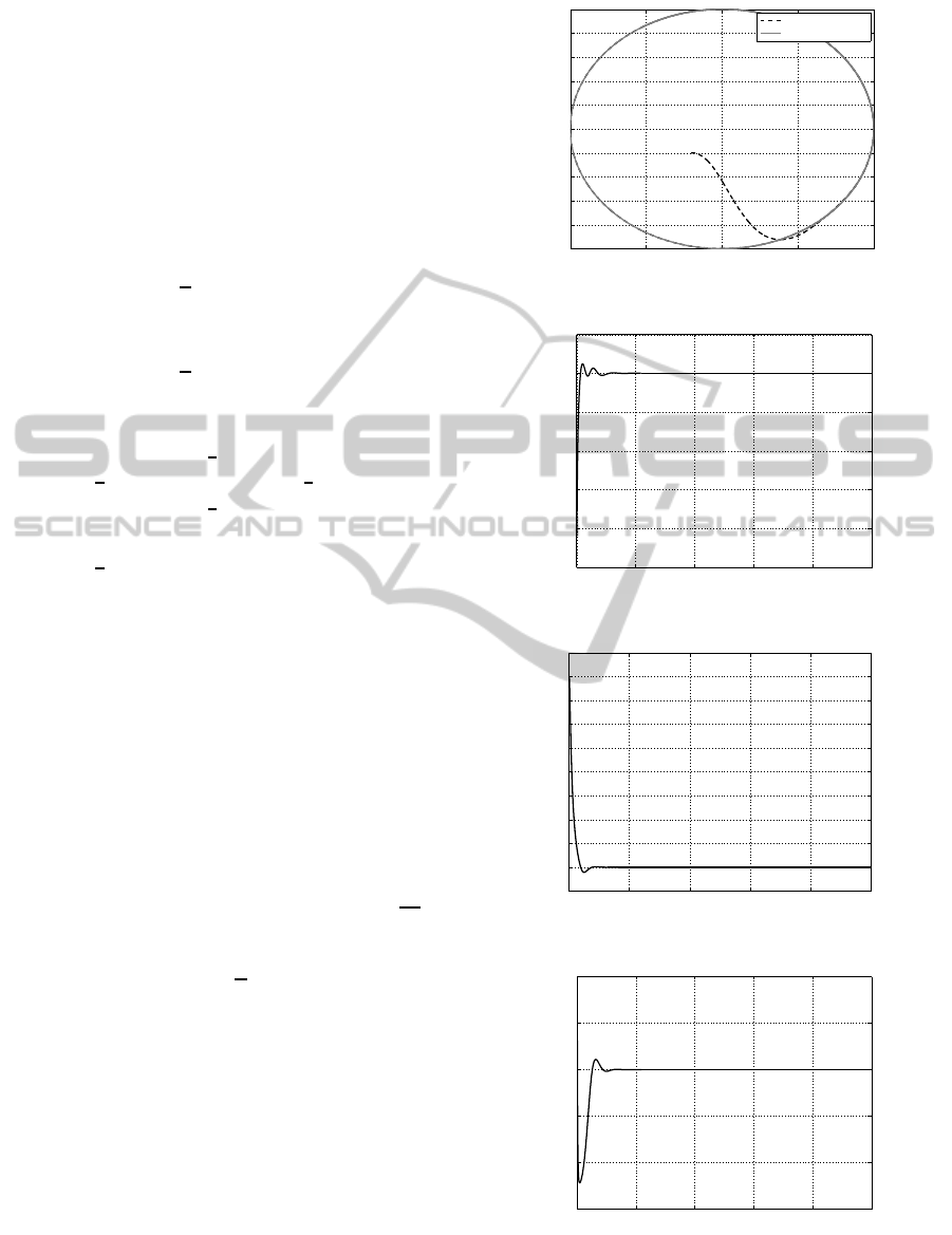
Circle. In Figures from 3 to 6 were presented the
plots from a simulation with the desired trajectory set
to a circle. From the plots presented in Figures 4-6
it can be observed that position tracking errors and
orientation error tend to 0.
Square Trajectory. In Figures 7-10 were presented
the plots for desired trajectory set to a square.
−10 −5 0 5 10
−10
−8
−6
−4
−2
0
2
4
6
8
10
x [m]
y [m]
Real trajectory
Desired trajectory
Figure 3: Real vs desired trajectory.
0 20 40 60 80 100
−2.5
−2
−1.5
−1
−0.5
0
0.5
time [s]
e
x
[m]
Figure 4: Error in cartesian space for x coordinate.
0 20 40 60 80 100
−1
0
1
2
3
4
5
6
7
8
9
time [s]
e
y
[m]
Figure 5: Error in cartesian space for y coordinate.
0 20 40 60 80 100
−1.5
−1
−0.5
0
0.5
1
time [s]
e
φ
[rad]
Figure 6: Error in cartesian space for ϕ coordinate.
NewApproachtotheArtificialForceConceptforSkid-steeringMobilePlatform
221
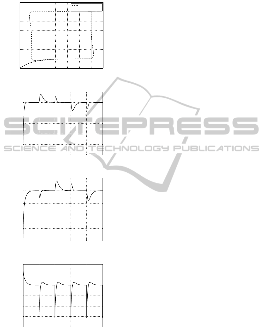
−2 0 2 4 6 8 10 12
−2
0
2
4
6
8
10
12
x [m]
y [m]
Real trajectory
Desired trajectory
Figure 7: Real vs desired trajectory.
0 20 40 60 80 100
−2.5
−2
−1.5
−1
−0.5
0
0.5
time [s]
e
x
[m]
Figure 8: Error in cartesian space for x coordinate.
0 20 40 60 80 100
−2
−1.5
−1
−0.5
0
0.5
time [s]
e
y
[m]
Figure 9: Error in cartesian space for y coordinate.
0 20 40 60 80 100
−2
−1.5
−1
−0.5
0
0.5
1
time [s]
e
φ
[rad]
Figure 10: Error in cartesian space for ϕ coordinate.
7 CONCLUDING REMARKS
In the paper the method of an artificial force was used
for the skid-steering mobile platform. In this method
an additional input to the model of dynamics has been
introduced making input matrix invertible. Differ-
ently than in previous publications, in considered ap-
proach, the platform has been modeled as a cart with
four independent, not coupled wheels.
Used method has shown that it gives good results
for different ways of modeling a skid-steering plat-
form. It implies that in future research, the use of arti-
ficial force concept will lead to proper work of control
algorithm and good enough trajectory tracking.
REFERENCES
Campion, G. and Motte, I. (2000). A slow manifold ap-
proach for the control of mobile robots not satisfy-
ing the kinematic constraints. IEEE Transactions on
Robotics and Automation, 16(6):875–880.
Caracciolo, L., Luca, A. D., and Iannitti, S. (1999). Tra-
jectory tracking control of a four-wheel differentially
driven mobile robot. In Proc. of the IEEE Int. Conf. on
Robotics and Automation, pages 2632–2638, Detroit.
D’Andrea-Novel, B., Campion, G., and Bastin, G. (2007).
Control of wheeled mobile robots not satisfying ideal
velocity constraints: A singular perturbation ap-
proach. Int. Journal of Robust and Nonlinear Control,
5(4):243–267.
Krsti´c, M., Kanellakopoulos, I., and Kokotovi´c, P. (1995).
Nonlinear and Adaptive Control Design. Wiley, New
York.
Maalouf, E., Saad, M., and Saliah, H. (2006). A higher level
path tracking controller for a four-wheel differentially
steered mobile robot. Rob. and Auton. Syst., 1:23–33.
Mazur, A. and Cholewi´nski, M. (2013). Virtual force
concept in steering mobile manipulators with skid-
steering platform moving in unknown environment. J.
Intell. Robot. Syst.
Mazur, A., Sasiadek, J. Z., and Cholewi´nski, M. (2013).
Control of mobile manipulator with skid-steering plat-
form moving in unknown terrain in presence of dis-
turbance. In Proc. of the 10th Int. Conf. on Inform. in
Control, Autom. and Rob., Reykjavik, Iceland.
Mohammadpour, E., Naraghi, M., and Gudarzi, M. (2010).
Posture stabilization of skid steer wheeled mobile
robots. In Proc. IEEE Int. Conf. on Robotics, Automa-
tion and Mechatronics, pages 163–169, Singapore.
Pazderski, D. and Kozłowski, K. (2008). Trajectory track-
ing of underactuated skid-steering robot. In Proc.
American Control Conf., pages 3506–3510, Seattle.
Samson, C. and Ait-Abderrahim, K. (1991). Feedback
control of a nonholonomic wheeled cart in cartesian
space. In Proc. of the IEEE Int. Conf. on Robotics and
Automation, pages 1136–1141, Sacramento.
ICINCO2015-12thInternationalConferenceonInformaticsinControl,AutomationandRobotics
222
