
Comparison of Two Radar-based Scanning-techniques for the Use in
Robotic Mapping
Paul Fritsche and Bernardo Wagner
Institute for Real Time Systems, Leibniz University Hanover, Applestr. 9A, Hanover, Germany
Keywords:
Radar, Trilateration, Mono-static Radar Network, Amplitude Sensing Ratio, 2D-Scanner, Robotic Mapping,
Occupancy Grid Mapping, Sensor-fusion.
Abstract:
This paper will introduce two radar-based scanning-methods and evaluate their application in robotic mapping.
Both approaches base upon a rotary joint, but with a fundamentally different angle estimation method to
estimate object locations inside the scanning area. The first part of this paper describes the relevant theory
behind both techniques and presents our considerations on erroneous influences. The focus of the second
part of this paper is laying on experiments. We discuss the results of our experiments and take a look on the
usability of both methods for occupancy grid mapping.
1 INTRODUCTION
The following article introduces two scanning meth-
ods, for mapping purposes in mobile robotics. Our
first method is based on a rotating mono-static radar
network, which determines the positions of objects
inside the scanning area via a continuously running
lateration algorithm. Our second method is based on
rotating radar sensors with an angle offset and a deter-
mination of the positions of objects through the Am-
plitude Sensing Ratio (ASR) technique.
A precise model of the environment is essential
in many areas of mobile robotics and builds the fun-
dament for localization and navigation. Commonly,
popular sensors like laser-scanners, sonar-sensors and
stereo-cameras have established themselves as state
of the art for most tasks in mobile robotics. Neverthe-
less, radar sensors frequently appear in field and res-
cue robotics (Adams et al., 2012) (Tadokoro, 2009),
but are seldom used to perform tasks like mapping
and localization. Radar can penetrate certain materi-
als, basically non-conductors, which provides advan-
tages in dusty, foggy, rainy or other harsh environ-
ments. But, limited resolution, noisy data, influence
of optical effects like refraction, reflection and ab-
sorption make the application in mobile robotics chal-
lenging.
The use of radar sensors in mobile robotics is
challenging but not impossible. The first appearance
of radar sensors in the robotic community is tracing
back to the Australian Centre for Field Robotics in the
early nineties, where fundamental work on probabilis-
tic SLAM algorithms in combination with radar was
developed (Clark and Whyte, 1998). Because of their
limited resolution and other aforementioned draw-
backs, radar sensors are not very suitable to use in
indoor environments. Nevertheless, (Detlefsen et al.,
1993) were investigating the use of radar sensors in
an industrial environment and (Marck et al., 2013) in
an office. As far as we can see, most radar sensor
principles in mobile robotics are based on mechan-
ical beam-forming. Usually, the radar beam is fo-
cussed via a parabolic antenna and panned mechan-
ically over the environment. Electrical beam-forming
through phased array antennas is not seen very often
in mobile robotics rather in automotive systems of the
car industry.
Besides beam-forming techniques, position esti-
mation can be achieved through lateration, which is
a common technique in radar networks for aircraft
surveillance. Lateration is a measurement method,
where the position of a point target is calculated of
distance information from n Sensors with known lo-
cations. The term trilateration refers to the measure-
ment of three distances to define the position of an ob-
ject (in contrast to triangulation, where three angles
are used to calculate an object’s position). The esti-
mation of surfaces with ultra-wide band (UWB) radar
networks has been studied experimentally in lab envi-
ronments, especially with lateration by (Mirbach and
Menzel, 2011) , envelopes of spheres by (Kidera et al.,
2008) and inverse boundary scattering algorithms by
365
Fritsche P. and Wagner B..
Comparison of Two Radar-based Scanning-techniques for the Use in Robotic Mapping.
DOI: 10.5220/0005524303650372
In Proceedings of the 12th International Conference on Informatics in Control, Automation and Robotics (ICINCO-2015), pages 365-372
ISBN: 978-989-758-122-9
Copyright
c
2015 SCITEPRESS (Science and Technology Publications, Lda.)

(Sakamoto, 2007). But, we can not see a link to the
field of robotic mapping with mobile robots, where
laser scanners are dominating. ASR techniques on a
rotary joint are common techniques in ground-based
radar systems for air-traffic control (Agilent, 2014).
For our experiments, we use frequency modulated
continuous wave (FMCW) radar sensors, which pro-
vide distance but no angle information of objects in-
side the observation area. The sensors work in 24
GHz ISM band and accordingly are limited in Ger-
many to a bandwidth B of 250 MHz, which corre-
sponds to a theoretical distance resolution ∆d of 0.6
m in dependency of the speed of light c
0
(See Equa-
tion 1).
∆d =
c
0
2B
(1)
The resolution ∆d of a radar sensor is equal to its
minimum detection range. The availability of sensors
with a high resolution depends on national and inter-
national bandwidth regulations. An UWB channel be-
tween 22 GHz to 26,65 GHz has been closed in 2013,
but is moved to 79 GHz for automotive purposes re-
cently (Schmid and Neubauer, 2007, p. 20).
A radar’s resolution is its capability to distinguish
objects. If the difference between the radial distances
of two or more objects to the sensor is less than its
resolution, then the sensor merges the two or more
distance information to one. Additionally, the detec-
tion of objects depends on their radar cross section
(RCS) and the background noise of the environment.
This article is organized as follows. In Section 2,
we present a short overview, how position estimation
via lateration and ASR techniques are solved. Besides
the theory and introduction to common terms, we ex-
plain the ghost target and non-point target problems
in radar networks which are based on lateration. Ad-
ditionally, we describe influences of errors related to
the power and range measurement accuracy of radar
sensors. The reader who is familiar to these topics
might go directly to Section 3, where the sensor prin-
ciples are described in the beginning. Further in this
section, we will describe our experiments, which re-
sults are discussed in Section 4. A brief summation of
the obtained knowledge is given in Section 5.
2 MATERIALS AND METHODS
Estimating the position of an object with a radar net-
work can be solved by standard lateration methods or
ASR techniques. In order to define an object’s posi-
tion in two-dimensional space, at least two sensors are
necessary. In case of lateration, two radii from two
range measurements at different positions can break
down the object’s position to two possible locations.
Usually, only one location is plausible due to the an-
tenna’s direction. In case of the ASR technique, the
position of an object can be estimated through the dif-
ference in the receiver power at two antennas which
are located at the same position but pointing into dif-
ferent directions. In this paper, we investigate the us-
ability of both methods in combination of a rotating
scanning unit to generate occupancy grid maps.
2.1 Principle of the Lateration
Technique
Lateration is a measurement principle to estimate the
positions of points with distance informations to a
known locations. If the distance to an unknown point
is given, then this point must be laying on a radius
(two-dimensional case) around our location. If two
locations are known, then two radii result in an inter-
section, which is the position of the point. Figure 1
demonstrates the basic of operation of the lateration
principle.
Ghost targets
d
Ant
d
11
d
21
d
12
d
22
S
1
S
2
O
1
O
2
✲
✻
x
y
Figure 1: The position of objects O can be estimated via the
distances d, which are measurend from different sensors.
Ghost targets represent a geometrical ambiguity.
For a two-dimensional space, n objects O
i
(i=1..n)
and m sensors S
j
(j=1..m) result in m · n equations
of circle. The euclidean distances between the sen-
sor positions S
j
(x
S j
,y
S j
) and the object positions
O
i
(x
Oi
,y
Oi
) are given by the following equations:
(x
S1
− x
O
i
)
2
+ (y
S1
− y
O
i
)
2
= d
2
i1
(x
S j
− x
O
i
)
2
+ (y
S j
− y
O
i
)
2
= d
2
i j
.
.
.
(x
Sm
− x
O
i
)
2
+ (y
Sm
− y
O
i
)
2
= d
2
im
(2)
The distance between an Object O
i
and an Sensor
S
j
is defined as d
i j
. The general description of the lin-
ear system of equations can be achieved through sub-
tracting the last equation (j=m) of Equations 2 from
ICINCO2015-12thInternationalConferenceonInformaticsinControl,AutomationandRobotics
366
all other equations ( j = 1...m − 1) (Schneider, 2013,
p. 8).
2 · (x
S1
− x
Sm
) 2 · (y
S1
− y
Sm
)
2 · (x
S2
− x
Sm
) 2 · (y
S2
− y
Sm
)
.
.
.
2 · (x
Sm−1
− x
Sm
) 2 · (y
Sm−1
− y
Sm
)
·
x
O
i
y
O
i
=
x
2
S1
− x
2
Sm
+ y
2
S1
− y
2
Sm
− d
2
i1
− d
2
im
x
2
S2
− x
2
Sm
+ y
2
S2
− y
2
Sm
− d
2
i2
− d
2
im
.
.
.
x
2
Sm−1
− x
2
Sm
+ y
2
Sm−1
− y
2
Sm
− d
2
im−1
− d
2
im
A ·~o
i
=
~
d
i
(3)
In reality, every sensor outputs measurement val-
ues with errors. The difference from the true value
occur due to limited accuracy and resolution. Hence,
the system of equations does not result in one sin-
gle solution if it is overdetermined. The system of
equation gets overdetermined if the radar network has
more sensors than the dimension of its measurement
space. Commonly, overdetermined systems of equa-
tion with no single solution get resolved through re-
gression. The most popular solution is the least mean
square method (Schneider, 2013, p. 8) (F
¨
olster, 2006,
p. 39).
Like it can be seen in Figure 1, ghost targets can
appear in radar networks. Ghost targets represent a
wrong data association, because like it is shown in
Equation 2, four objects can be theoretically calcu-
lated if two objects are placed in front of two sen-
sors. Ghost target appear if the sensor’s resolution is
smaller than the half antenna distance (d
Ant
). A de-
tailed derivation of the ghost target cases can be seen
in (Rabe et al., 2009).
In order to resolve the ghost target problem,
(F
¨
olster and Rohling, 2005) present the button-up
data association method. In two-dimensional space,
at least three radar sensors are required. In order to
distinguish ghost objects from real objects, the ob-
servation area in front of the sensor network is dis-
cretized into a finite set of possible object positions.
Then, a simple minimum distance calculation is done.
For each point, an error value E(x, y) can be calcu-
lated from the square of the minimum distance of the
point to the sensor S
j
minus the distance d
i j
between
object O
i
and sensor S
j
, summarized over all n sen-
sors (See Equation 4).
E(x, y) =
n
∑
i=1
min
d
i j
∈OL
i
(d
i j
− d(x, y))
2
(4)
This calculation results in the lowest error values
at points that are closest to the real objects. After-
wards, a threshold distinguishes likely ghost target
from real objects.
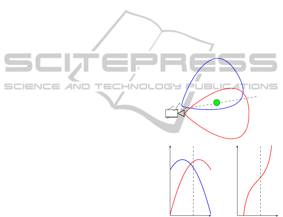
2.2 Principle of the ASR Technique
Every location in front of an antenna, is connected to
a different antenna gain factor. For example, if we
walked on a radius around a loudspeaker with closed
eyes, we would have a feeling when we would be
walking directly in front of it, because then the sound
appears to be louder. A similar effect is used for the
ASR technique. If we point two radar antennas in
slightly different directions, then the power at the re-
ceiver antennas would not be equal, due to different
antenna gains.
O
Angle α
Power at receiver antenna P
e
Angle α
ASR
Figure 2: The position of an object O inside the observation
area can be estimated via the difference of power of into
different direction facing receiver antennas.
The measured power at the receiver antenna P
e
of
an object depends on the angle α between antenna and
object. Two sensors, which are facing into different
directions, but placed at the same location, measure
the same distance but different power P
e
. If a function
for the power in dependency of the angle position of
the object is given, then the object’s position can be
estimated via the ASR function (See Figure 2).
ComparisonofTwoRadar-basedScanning-techniquesfortheUseinRoboticMapping
367

The angle of an object inside the observation area
can be estimated through the Amplitude Sensing Ra-
tio (ASR). In a two-dimensional case, the ASR for
the azimuth is defined by a delta signal (∆) and a sum
signal (
∑
), which are derived from the powers at the
receiver antennas (B
¨
uhren, 2008, p. 34-35).
ASR =
∆
Σ
=
P
e1
− P
e2
P
e1
+ P
e2
(5)
In order to obtain information in three-
dimensional space, the elevation needs to be
estimated through an additional sensor beam.
2.3 Consideration on Erroneous
Influences
Estimating the position of objects with lateration and
ASR requires sensors with very high range or power
accuracy. Nevertheless, every sensor has a measure-
ment error. In case of lateration, the maximum po-
sition measurement error σ
PD
can be approximated
by the maximal range measurement error σ
R
max
of all
sensors and the angle α (See Equation 6). The range
measurement accuracy is defined by the root-mean-
square (rms) measurement error σ
R
(Curry, 2005, p.
167). Figure 3 clarifies the relation between the range
measurement error σ
Ri
, the angle α and the position
measurement error σ
PD
graphically.
2·σ
R1
sinα
2·σ
R2
sinα
α
Figure 3: Area of ambuguity, which is caused by the two
rms-errors σ
R1
and σ
R2
.
If the ratio between distance of the object and the
antenna distance gets higher, then the rhomb-shaped
area of ambiguity gets wider. In Figure 5, it can be
seen that the area of ambiguity of a point target ap-
pears almost to be a line. From Equation 6, it can
be seen that the accuracy of a lateration based radar
network is getting very bad at the sides of the sensor
network, where α is approaching zero.
σ
PD
≈
σ
R
max
sinα
(6)
The rms error σ
R
depends basically on the signal-
to-noise ratio of the received signal. The signal-to-
noise ratio is higher and results accordingly in a bet-
ter accuracy, if the RCS of an object is higher. Conse-
quently, our radar principle results in better position
estimations for objects with high RCS. But, objects
with a high RCS are entering the observation area of
a rotating scan earlier from the sides then objects with
a lower RCS, hence an object with high RCS suffers
more from the position estimation error σ
PD
.
Besides the range measurement accuracy, the res-
olution of a radar sensor has important impact on the
reliability of the scan results. A radar sensor will not
distinguish two point targets, if they are inside a so
called resolution cell. For example, a radar with a
resolution of 1 m, can not differ between two or more
objects which are inside a band, with the wide of 1
m, around the sensor and would output the detection
of only one range value somewhere between those
two objects. The lateration technique results only in
correct position estimation if all sensors of the radar
network are measuring the same distance to the same
point. But, single point targets are very rare in stan-
dard environments. Usually, every sensor of a radar
network measures the distance to a different point tar-
get, which results in wrong position estimations.
The precondition for the ASR technique is the
placement of sensors at the same location. The closer
the antennas are placed to each others, the more ex-
actly is the result and the same centres of reflection
of a target can be assumed in a ASR radar network.
Unfortunately, the accuracy and resolution of the re-
ceiver power P
e
can not be defined, because it is de-
pending on the RCS of the object as well (See radar
equation). There is a fluctuation of the RCS, which
can be explained by the Swerling Models. A. Ludloff
explains in (Ludloff, 1998, p. 3-14) how the fluctua-
tion can be modelled. The model is based on the idea
that one radar target exists of multiple reflector ele-
ments, which are distributed over the volume of the
target. The model assumes the reflector elements to
be isotropic and with the same RCS and neglects the
effects of reflection or shadows among themselves.
Through overlapping of reflected radar waves on this
multiple isotropic reflector elements, phase differ-
ences result in complex interferences. This model ex-
plains the appearance of high fluctuation of the RCS
(and accordingly the receiver power), even if the as-
pect angle is changed only slightly. To sum it up, an
exact estimation of the RCS, even of standard geome-
tries, is not possible in the real world and fluctuation
effects disturb the reliability of the position estimation
results via ASR techniques.
ICINCO2015-12thInternationalConferenceonInformaticsinControl,AutomationandRobotics
368
3 EXPERIMENTS
The following section describes first experiments with
both sensor principles. Therefore, two scans at the
same location but with different sensor principle have
been performed. Both sensor principles, the lateration
technique and the ASR technique, have been set up
on a rotating platform. Our radar sensors work with a
center frequency of 24 GHz with a bandwidth of 250
MHz, which is the reason for the low resolution. Fur-
thermore, our radar beam is not very focussed. The
setup of both experiments can be seen in Figure 4.
β β
Figure 4: The left drawing shows the scanner with the lat-
eration setup. The right drawing presents the ASR setup.
Both setups are based on a rotating joint and its angle posi-
tion β.
Our first scans have been performed in an indoor
environment. We neglect that we perform a 2D scan
inside a 3D environment. In order to have a landmark,
we were placing a point target (an aluminium corner
reflector), at the same hight like our sensor unit, inside
our scan area. A serial of scans of a hallway with both
principles has been performed for further evaluation.
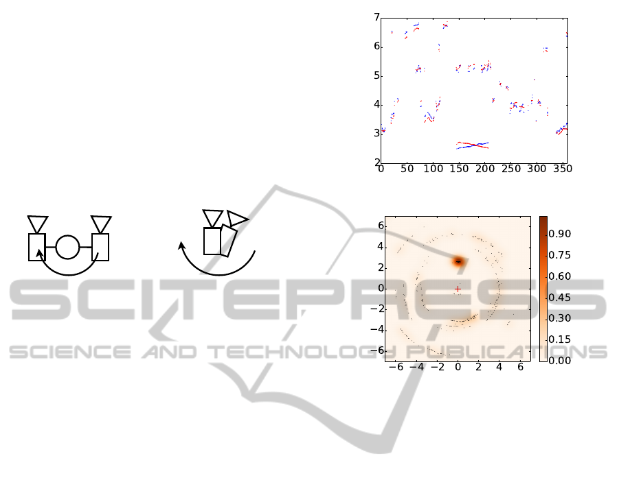
3.1 Single Scan with the Lateration
Technique
In order to evaluate the sensor principle, we were per-
forming first scans of standard objects in an indoor
environment. The goal of the first experiment is to
find out about error influences in our sensor princi-
ple. As mentioned before, a limited resolution can be
problematic in an indoor environment, like our office.
There might be metallic radiators, steal-beams behind
the walls, computer towers and many other objects
that can have a RCS huge enough of being detected by
our radar sensor. Our first scan results are presented
in Figure 5.
The measurement contains the accumulation of
five 360
◦
degree scans with a step size of 0.7
◦
de-
grees. Not every measurement cycle leads to a suc-
cessful position estimation. A successful position es-
timation can be processed if both sensors detect an
object.
The probability of occurrence of two objects, with
a smaller difference of their radial distances to the
sensor than the radar’s resolution, is high, hence we
β
p(0)
d
1
and d
2
in m
y in m
x in m
Figure 5: Above: This diagram presents the distance infor-
mations of the two sensors during a 360
◦
scan of the ro-
tating platform. It can be seen that the corner reflector is
the only trustful point target in our office environment (See
red circle). The characteristics of the distances of the two
sensors d
1
and d
2
is caused by the rotation of the platform,
where one sensor is approaching and the other sensor gets
more far away during a rotation. The distances of non point
target do not have a symetric characteristic. Below: This
diagram depicts a top view on our scanning area. The red
cross represents the location of the sensor unit. The point
target results in an accumulation of distance values. The
remaining spread is only cause by the sensor measurement
error σ
R
. Accordingly, the point target has the highest prob-
ability p(0) for its correct position estimation.
can rarely trust our scan results, if performed in an
indoor environment. For fundamental research, our
radar sensors with an resolution of approximately 0.6
m are sufficient.
3.2 Single Scan with the ASR Technique
For our investigation on the ASR technique, we were
using exactly the same scene and same sensors. In-
stead of placing the sensor at two different positions,
the ASR technique works the best if both sensors are
placed close as possible, but with a small shift regard-
ing the antenna direction. Our scan results are pre-
sented in Figure 6.
The measurement contains the accumulation of
ComparisonofTwoRadar-basedScanning-techniquesfortheUseinRoboticMapping
369
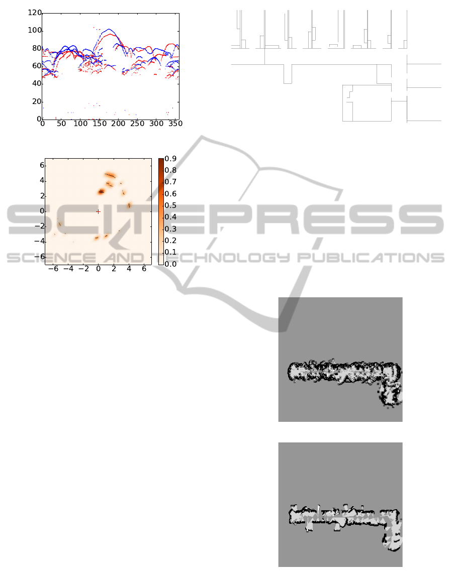
β
p(0)
P
e1
and P
e2
in dBy in m
x in m
Figure 6: Above: This diagram depicts the power at the
receiver antennas P
e1
and P
e2
during a 360
◦
scan. The non-
point target effect does not effect the results. The main er-
ror influence is caused by the low resolution and the wide
beam size of the radar sensor. An angle estimation of ob-
jects through the ASR in an traditional way is impossible,
because of the non-uniform distribution of the power val-
ues. Below: This diagram presents a 2D scan of our office
environment via the ASR technique. The red cross shows
the location of the sensor unit.
five 360
◦
degree scans with a step size of 0.7
◦
degrees
as well. The distribution of the powers at the receiver
antennas is not suitable for a traditional ASR based
position estimation, because the high amount of ob-
jects does not allow to develop regression functions
for the ASR of our experiment. Nevertheless, we can
assume to have an object perpendicular in front of the
sensor unit if the ASR is close to zero. The ASR
method requires, besides calibration of the range mea-
surement of the sensors an calibration of the antenna
directions.
3.3 Scan of Hallway
In order to compare the suitability for robotic map-
ping of both sensor principles, a serial of scans has
been recorded of a hallway. To avoid influences of
control and odometry errors of our robots, all scans
have been performed at known poses (See Figure 7).
The locations of the sensor unit have been cho-
*
*
*
*
*
*
*****************
Figure 7: Ground truth of the office environment with scan
positions of the sensor unit.
sen under the consideration of the minimal detectable
distance of the radar sensors, which is equal to their
resolution. The minimal detectable distance is a rea-
son, why radar sensors with low resolution are only
suitable for outdoor environments with larger scale.
Like mentioned before, a 2D experiment in per-
formed in a 3D environment, hence metallic objects
with rectangular shape elements, like office lamps, get
layered into the map as well. Occupancy grid maps,
which are obtained via classical inverse sensor model
(Elfes, 1989), are presented in Figure 8.
Figure 8: Above: This occupancy grid map is built from
raw data of the lateration technique. The wide spread of the
sensor data is caused by non point target situations. Below:
This map is obtained from of the ASR technique.
ICINCO2015-12thInternationalConferenceonInformaticsinControl,AutomationandRobotics
370

4 RESULTS AND DISCUSSION
This section will give an interpretation of the obtained
results of the experiments, which have been described
in Section 3.
Figure 5 presents the results of one single scan in-
side an office environment, where a point target has
been placed. The position of the point target gets es-
timated very well and the remaining spread of the es-
timated points is caused by the range measurement
error σ
R
i
of the sensors. Tests with different distances
between corner reflector and sensor unit have proven,
that a rhomb-shaped area of ambiguity is achieved.
This has been explained for a static case on Figure 3.
The position of non point targets gets not estimated
very well. The sensors measure distances to different
points. This results in a non symmetric characteristics
of the distance values d
1
and d
2
. Consequently the lat-
eration algorithm calculates the wrong positions.
Figure 2 presents the result of a single scan with
the ASR technique. The corner reflector gets the high-
est accumulation of detected object locations, like in
case of the lateration technique. Theoretically, the
characteristics of the receiver powers P
e1
and P
e2
sup-
posed to have a phase difference equal to the angle
shift of the antenna directions. But, the fact that we
can not place both sensors in exactly the same point
leads to the fact that again we can not measure exactly
the same point target. Furthermore, we can not guar-
antee both antenna diagrams to be exactly the same
due to fabrication tolerances. Nevertheless, we can
assume a position of an object, if the ASR is close to
zero.
In order to evaluate if the lateration and ASR tech-
nique are suitable for robotic mapping, we built two
occupancy grid maps with an inverse sensor model
(Thrun et al., 2005, p. 279-300) which we applied on
the raw data that has been recorded during a scan of
a hallway (See Figure 7). The wide of the hallway is
approximately 2m and it has a curve at 20m. Figure 8
displays both results. The ASR technique results in a
quite good map. Consequently, we see possibilities to
map even indoor environments with radar sensors of
low resolution. The minimum detection range, which
is equal to the resolution of the sensor, should be con-
sidered (See Equation 1). To enhance the result of the
lateration technique, more sensors should be used. In
general, both principles suffer from bad resolution of
the radar sensors. Optical effects like double reflec-
tions inside a narrow hallway have a negative effect
on the methods as well.
5 CONCLUSION
Robust localization and navigation in hazardous and
tough environments are still a difficult issue in field
robotics research. Dust, rain, fog or inadequate illu-
mination are conditions, which make popular sensors,
such as laser scanners or cameras, not suitable. Radar
overcomes the aforementioned difficulties.
In this article, we were investigating two new
scanning methods for mobile robotics and took a
closer look on failure influences. We were focusing
on three influences. First, the range measurement er-
ror of the sensor itself. Second, the influence of wrong
position estimation due to non point targets regarding
the lateration technique. Third, we investigated if the
received power of the receiver antenna is reliable for
position estimation, in an environment with multiple
targets. We discovered that the influence of non point
targets has a huge influence, especially in a setup with
only two sensors. This effect can be scaled down by
increasing the number of sensors.
There exists several mapping algorithms. An
overview is given by Thrun in (Thrun, 2002, p.7).
Thrun introduces algorithms, which are suitable for
mapping with unknown robot poses, which is named
simultaneous localization and mapping (SLAM). In
this article, we focus on mapping with known poses,
which is simpler. But, mapping with known poses is
leading to more promising results, because odometry
and control errors do not influence the map. Occu-
pancy grid mapping with Bayes filter is the most pop-
ular probabilistic representation of a map. Our pro-
posed scanning methods are suitable for occupancy
grid mapping with a classical inverse sensor model.
As far as we can see, the ASR technique results in
better maps.
The proposed radar-based scanning methods are
an alternative to mechanical and electrical beam-
forming methods. Mechanical beam-forming tech-
niques require an antenna and electrical beam-
forming techniques need phase array radars, which
are commonly more expansive. Although no antenna
construction is required, our methods needs more than
one sensor.
From one single 360
◦
-scan of a radar-scanner,
which pivots mechanically a focused beam over a sur-
rounding, a more continues distribution of the mea-
surement can be expected. Our proposed methods
base on antennas with a very large beam width and
objects with a high RCS occlude a larger scene conse-
quently. However, the lateration technique is record-
ing more than one measurement of an object dur-
ing one scan rotation, which raises the possibility
of a correct detection of an object. An advantage
ComparisonofTwoRadar-basedScanning-techniquesfortheUseinRoboticMapping
371

over techniques with focused beams is the possibil-
ity to perform 3D scans as well, which would be me-
chanically complicated in case of mechanical beam-
forming techniques and is only known in combination
with electrical beam-forming radars. Unfortunately,
the lateration technique suffers more from bad accu-
racy and resolution, wrong calibration or asynchro-
nism of measurements than traditional techniques.
The detection of different centres of reflection is the
main problem of the lateration technique. The ASR
technique results in pretty well raw data, although a
traditional ASR curve approximation is not possible
in an environment with multiple objects. In this arti-
cle we propose the simple solution of filtering all data,
with a threshold close to a ASR of zero. This results
in less wrong position estimations than the lateration
technique.
REFERENCES
Adams, M., Mullane, J., and Jose, E. (2012). Robotic Nav-
igation and Mapping with Radar. ARTECH HOUSE.
Agilent (2014). Techniques for Precision Validation of
Radar System Performance in the Field. Agilent Tech-
nologies.
B
¨
uhren, M. (2008). Simulation und Verarbeitung von
Radarziellisten im Automobil. PhD thesis, Universit
¨
at
Stuttgart.
Clark, S. and Whyte, H. D. (1998). The design of a high
performance mmw radar system for autonomous land
vehicle navigation. In Field and Service Robotics.
Curry, G. R. (2005). Radar System Performance Modeling.
Artech House.
Detlefsen, J., Rozmann, M., and Lange, M. (1993). 94 hgz
3-d imaging radar sensor for industrial environments.
EARSeL Advance in Remote Sensing.
Elfes, A. (1989). Using occupancy grid mapping for mobile
robot perception and navigation. IEEE Computer.
F
¨
olster, F. (2006). Erfassung ausgedehnter Objekte durch
ein Automobil-Radar. PhD thesis, Technische Univer-
sit
¨
at Hamburg-Harburg.
F
¨
olster, F. and Rohling, H. (2005). Data association and
tracking for automotive radar networks. IEEE Trans-
actions in Intelligent Transportations Systems.
Kidera, S., Sakamoto, T., and Toru, S. (2008). High-
resolution and real-time three-dimensional imaging
algorithm with envelopes of spheres for uwb radars.
IEEE Transactions on Geoscience and Remote Sens-
ing.
Ludloff, A. (1998). Praxiswissen Radar und Radarsig-
nalverarbeitung. vieweg.
Marck, J. W., Mohamoud, A., and Houwen, Eric vd
qnd Hejster, R. v. (2013). Indoor radar slam . a radar
application for vision and gps denied environments. In
10th European Radar Conference.
Mirbach, M. and Menzel, W. (2011). A simple surface es-
timation algorithm for uwb pulse radas based on tri-
lateration. IEEE International Conference on Ultra-
Wideband.
Rabe, H., Denicke, E., Armbrecht, G., Musch, T., and
Rolfes, I. (2009). Considerations on radar localiza-
tion in multi-target environments. Advances in Radio
Science.
Sakamoto, T. (2007). A fast algorithm for 3-dimensional
imaging with uwb pulse radar systems. IEICE Trans-
action on Communication, pages 636–644.
Schmid, G. and Neubauer, G. (2007). Bestimmung der ex-
position durch ultra-wideband technologien. Techni-
cal report, Bundesamt f
¨
ur Strahlenschutz.
Schneider, M. (2013). LSB-Methode Bestimmung von Dis-
tanzunterschieden mittels parametrierter Schwebun-
gen. PhD thesis, Universit
¨
at Rostock.
Tadokoro, S. (2009). Rescue Robotics - DDT Project on
Robots and Systems for Uraban Search and Rescue.
Springer.
Thrun, S. (2002). Robotic Mapping: A Survey. School of
Comuputer Science.
Thrun, S., Burgard, W., and Fox, D. (2005). Probalistic
Robotics. The MIT Press.
ICINCO2015-12thInternationalConferenceonInformaticsinControl,AutomationandRobotics
372
