
Assistive Robot for Standing with Physical Activity Estimation
based on Muscle Arrangements of Human Legs
Daisuke Chugo
1
, Takahiro Yamada
1
, Satoshi Muramatsu
2
, Sho Yokota
3
and Hiroshi Hashimoto
4
1
School of Science and Technology, Kwansei Gakuin University, Sanda, Hyogo, Japan
2
School of Information Science and Technology, Tokai University, Hiratsuka, Kanagawa, Japan
3
Department of Mechanical Engineering, Toyo University, Kawagoe, Saitama, Japan
4
Advanced Institute of Industrial Technology, Shinagawa, Tokyo, Japan
Keywords: Standing Assistance, Musculoskeletal Model, Joint Traction, Physical Activity Estimation.
Abstract: A physical activity estimation scheme is proposed for patients who use a robot for standing assistance. In
general, conventional assistive robots do not require patients to use their own physical strength to stand,
which leads to decreased strength of the elderly. Therefore, an assistive robot that maximally uses a
patient’s remaining physical strength is desired. The assistive robots can achieve this objective by
estimating the physical activity of the patient when they stand. The activity estimation proposed here is
primarily based on a human musculoskeletal model of a lower limb, which exhibits a biarticular muscle
function. The patient generates a natural standing motion using the biarticular muscle function, and the
proposed model enables the assistive robot to estimate the patient’s physical activity, without using
biosensors, such as electromyographs, which are normally stuck on patients. The proposed estimation is
implemented with a prototype assistive robot that assists elderly patients to use their remaining physical
strength based on the estimated results, thus testing the effectiveness of the proposed method.
1 INTRODUCTION
The act of standing may be the most serious and
important activity in the daily life of an elderly
person lacking physical strength (Alexander et al.,
1999; Hughes et al., 1996). However, assisting
elderly patients to stand is a heavy task for
caregivers and this can be the primary source of the
lumbago that many experience (Cabinet Office,
Government of Japan, 2011). Therefore, creating a
care service robot capable of assisting the elderly
when they stand is important, and thus many such
assistive devices have been developed and presented
in previous works (Nagai et al., 2003; Funakubo et
al., 2001).
In Japan, elderly people requiring assistance in
daily life are classified into five different care levels
(Cabinet Office, Government of Japan, 2011), where
requiring care level 1 is a minor and requiring care
level 5 is a serious condition. Generally, the elderly
whose care level is 1 or 2 have difficulty in standing
on their own but are able to perform normal daily
life activities if standing assistance is provided.
However, in many cases, standing assistance devices
provide all the power necessary for the patient to
stand and do not use the patient’s remaining physical
strength. Thus, the patient’s physical strength
decreases (Hirvensalo et al., 2000). In fact, between
2002 and 2003, more than 10% of care level 1
patients were subsequently assigned to higher care
levels in next year (Cabinet Office, Government of
Japan, 2011). Thus, to improve the quality of life of
elderly patients with low care levels, assistive robots
should use the patient’s remaining physical strength.
However, no studies have been conducted toward
this end.
Therefore, we have developed a novel assistive
robot designed to aid patients in using their own
physical strength to stand (Chugo et al., 2012). The
robot is based on a walker (a popular assistance
device for aged people in normal daily life) and uses
a support pad, which is actuated by manipulators
with three degrees of freedom (Fig.1), to assist
patients in standing.
To maximally utilize the remaining physical
strength of a patient while providing standing
assistance, the robot is required to accurately
estimate the physical activity of the patient because
the robot is required to coordinate its assistive force
35
Chugo D., Yamada T., Muramatsu S., Yokota S. and Hashimoto H..
Assistive Robot for Standing with Physical Activity Estimation based on Muscle Arrangements of Human Legs.
DOI: 10.5220/0005527400350043
In Proceedings of the 12th International Conference on Informatics in Control, Automation and Robotics (ICINCO-2015), pages 35-43
ISBN: 978-989-758-123-6
Copyright
c
2015 SCITEPRESS (Science and Technology Publications, Lda.)
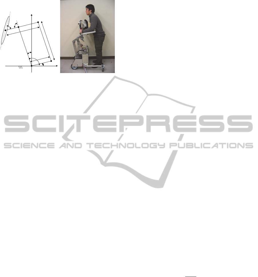
Actuator 2
Actuator 1
o
p
Actuator 3
x
y
α
β
L
1
L
2
L
3
L
i
n
k
1
L
i
n
k
2
θ
1
θ
2
θ
3
(a) Flame kinematic model. (b) Overview of our robot.
Figure 1: Our developed robot for standing assistance.
accordingly. However, generally, such estimations
without biosensors, as electromyographs (EMG), are
difficult; further, physical activity estimation with
biosensors, which are required to be stuck on the
patient, is impractical because assistance robots
should be low cost and easy to use.
Previous works have proposed physical activity
estimation using human models comprising linkages
and joints without such biosensors (Nuzik et al.,
1986; Hatsukari et al., 2009). These schemes
evaluate the patient’s physical activity using joint
traction, which is calculated using the kinematical
model as an index. However, many muscles generate
human body movements, and traction, which
muscles can generate maximally, changes according
to the relative positions of bones and muscles.
Therefore, maximum joint traction is not constant
but it changes according to the patient’s posture.
During a standing motion, the patient’s posture
changes considerably, which should be taken into
consideration when evaluating a patient’s physical
activity.
Therefore, in this paper, we propose a real-time
physical activity estimation for patients using a
standing assistance robot without additional
biosensors. The paper is organized as follows: in
Section 2, we propose an estimation scheme of a
patient’s activity according to their posture during
the standing motion using a human musculoskeletal
model of a lower limb, which expresses a biarticular
muscle function; in Section 3, we demonstrate an
assistance control scheme on our robot, which uses a
patient’s strength based on estimated results; in
Section 4, we provide experimental results obtained
using our prototype; and Section 5 concludes this
paper.
2 PHYSICAL ACTIVITY
ESTIMATION
2.1 Overview of Proposed Estimation
Scheme
In the linkage model of a human (Nuzik et al., 1986;
Hatsukari et al., 2009), a joint traction is used as an
index of a patient’s load. However, a joint traction
does not consider the posture of the patient, and in
some cases, this index and the experience of nursing
specialists are different, especially when the patient
is in a half-sitting posture. When the patient stands,
the muscles shown in Fig. 2 generate the lifting
motion (Nishida et al., 2011). Many muscles (shown
in Table 1) are used to accomplish the standing
movement, and the traction, which muscles can
generate maximally, changes according to the
relative position between frames and muscles.
Thus, we propose a novel physical activity
estimation scheme that takes all this into
consideration. In this paper, we focus on the traction
of the knee and waist joints, which are the main
forces propelling the patients to stand. Our proposed
algorithm is as follows:
First, we derive the required traction (knee joint
req
k
and waist joint
req
k
) to accomplish a standing
motion with our assistive robot.
Second, we derive the maximum traction (knee
joint
max
k
and waist joint
max
k
) the muscles can
generate for the posture at this time.
Comparing the two derived tractions, we
evaluate the physical activity of patient
i
,
which demonstrates how much the patient uses
their own physical strength as compared with
their maximum power (1). i is the identification
character. (For example, in the case of the knee
joint, i is k.)
max
i
req
i
i
(1)
2.2 Derivation the Required Traction
To estimate the applied load to each joint, we
approximate human motion based on the movement
of the linkage model on a two-dimensional (2D)
plane (Nuzik et al., 1986). Using this model, we can
derive the traction of each joint and estimate the
patient’s load.
ICINCO2015-12thInternationalConferenceonInformaticsinControl,AutomationandRobotics
36
hip
knee
ankle
1
2
3
4
5
6
7
8
9
Figure 2: Muscle arrangements in the human leg.
Table 1: Human leg muscles.
20.0
23.0
8.7
60.2
248.1
43.5
247.6
99.1
19.7
Physical Areas [cm
2
]
Gluteus masimum (GMAX)9
Iliopsoas (IL)8
Biceps femoris and short head (BFSH)7
Semimenbranosus (SM)6
Vastus lateralis (VAS)5
Rectus femoris (RF)4
Soleus (SOL)3
Gastrocnemius (GAS)2
Tibialis anterior (TA)1
Muscle actuatorNo
20.0
23.0
8.7
60.2
248.1
43.5
247.6
99.1
19.7
Physical Areas [cm
2
]
Gluteus masimum (GMAX)9
Iliopsoas (IL)8
Biceps femoris and short head (BFSH)7
Semimenbranosus (SM)6
Vastus lateralis (VAS)5
Rectus femoris (RF)4
Soleus (SOL)3
Gastrocnemius (GAS)2
Tibialis anterior (TA)1
Muscle actuatorNo
The assistance system is designed in such a way
that patients lean on the pad and grasp the armrest
while standing with our assistance (we will explain
our prototype more closely in the next section),
which means that our system uses the pad to apply
force to the patient’s chest and the armrest to apply
force to their forearm. These forces move vertically
(at the pad) and horizontally (at the armrest).
Considering these conditions, we propose a linkage
model that approximates the human body with our
assistance device (see Fig. 3).
0
x
y
(x
1
,y
1
)
(x
2
,y
2
)
(x
3
,y
3
)
(x
4
,y
4
)
(x
5
,y
5
)
f
armrest
f
pad
(x
e
,y
e
)
(x
s
,y
s
)
(x
w
,y
w
)
(x
k
,y
k
)
(x
a
,y
a
)
req
a
req
k
req
w
req
s
req
e
5
4
3
2
1
Link1
Link2
Link3
Link4
Link5
Link6
req
e
Link1
f
armrest
f
yarmrest
f
xarmrest
f
xe
f
ye
m
1
g
l
4
l
5
Figure 3: Linkage model of a human.
This model consists of six linkages. The armrest
applies the assistance force (
armrest
f
) to the center
position of Link 1 and the support pad applies the
force (
pad
f
) to the center position of Link 3.
i
m
is
mass of the link (
6,,1
i
) and
i
I
is the moment
of inertia.
ii
yx ,
is the position of the center of
gravity on each link, and
ii
yx ,
(i = a, k, w, s, and
e) is the position of each joint. We assume that each
linkage is in pillar form with its mass distributed
uniformly.
Using the balance of applied force and its
moment, we can derive the required traction of each
joint as (7) and (8). Our robot measures the user’s
posture using the kinematical information provided
by the assistance manipulator and a laser range
finder, which is equipped as shown in Fig. 1(b),
without additional biosensors that would have to be
stuck onto the patient. Using these equations, we can
calculate the required traction for each joint (
req
k
,
req
k
). For further information, please refer to our
previous paper (Chugo et al., 2012).
req
swsws
wsws
ww
ypadwxpadw
yarmresttsxarmrestts
req
w
Igyxxxyym
gyxxxyym
gyxxxyym
fxxfyy
fxxfyy
33111
222
33333
33
(2)
req
wwkwk
wkwk
wkwk
kk
ypadyarmrestkw
xpadxarmrestkw
req
k
Igyxxxyym
gyxxxyym
gyxxxyym
gyxxxyym
ffxx
ffyy
44111
222
333
44444
(3)
Here, we use body parameters chosen from a
standard body of data of Japanese adult males
(Okada et al., 1996); see Table 2. To derive the
required body parameters for calculating the
moment force, we measure the length of each body
segment and the mass of the entire body of each
individual patient.
2.3 Deriving the Maximum Traction
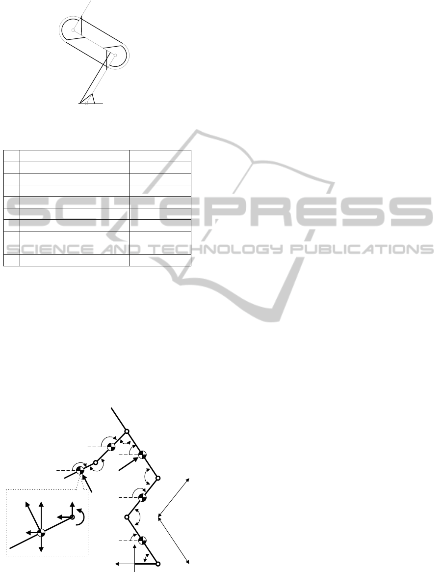
In the field of biomedicine, a human
musculoskeletal model that considers the role of
both an antagonistic muscle and a biarticular muscle
has been proposed (see Fig. 4) (Oshima et al., 1999).
This model shows that the antagonistic muscle and
the biarticular muscle interact to generate human
body movement.
AssistiveRobotforStandingwithPhysicalActivityEstimationbasedonMuscleArrangementsofHumanLegs
37

Table 2: Human body parameters.
No Name M [%] C.G [%] K [%] Length [m] *
1 Forearm 3.2 41.5 27.9 0.35
2 Humerus 5.4 52.9 26.2 0.39
3 Trunk 57 49.3 34.6 0.48
4 Femur 22 47.5 27.8 0.61
5 Leg 10.2 40.6 27.4 0.56
6 Foot 2.2 59.5 20.4 0.26
M The mass ratio of the body segment to the mass of the body.
C.G. The ratio of segmental length, which shows the location of
the center of gravity on the longitudinal axis.
K The ratio of the gyration radius of the body segment to the
length of its segment.
We know from previous research (Oshima et al.,
1999) that when the maximum force each muscle
can realize at the ankle joint is
1me
F
,
2me
F
,
3me
F
,
1mf
F
,
2mf
F
, and
3mf
F
, the output distribution of the force at
the ankle joint is expressed kinematically as a
hexagon (see Fig. 5).
The directions of
1me
F
and
1mf
F
are parallel to the
leg, the directions of
2me
F
and
2mf
F
are parallel to
the straight line that connects the waist and ankle
joints, and the directions of
3me
F
and
3mf
F
are
perpendicular to the leg. Furthermore, Oshima et
al.’s previous research demonstrates that there is a
relationship between the force output vector and the
activation level
i
of the muscle working in the
force output direction. This relationship is shown in
Fig. 4, and our system can estimate the activation
level of each muscle using the output force at the
ankle joint. For example, when the output force is
example
F
as in Fig. 4, the direction of the force
vector is between e and f.
Therefore, the activation levels of each muscle
are
%100
31
ee
,
%0
31
ff
, and
%50
22
fe
, as shown in Fig. 4.
Using this model, we propose a physical activity
estimation scheme of a patient according to their
posture. First, our system calculates the required
traction of the waist joint
req
w
and of the knee joint
req
k
using (2) and (3), respectively. From the
kinematical relationship shown in Fig. 4, the force
output vector
yx
ff ,
at the ankle joint is derived:
5544 5 54 4
55 5 5
sin sin cos cos
sin cos
req
w
req
k
x
y
f
ll l l
f
ll
(4)
defabcd
0
100
0
100
0
100
f1 e1
f2 e2
f3 e3
Muscle Activation level [%]
F
example
e
1
e
2
f
1
f
2
e
3
f
3
a
b
c
d
e
f
F
me2
F
mf1
F
me3
F
me1
F
mf2
F
mf3
F
example
waist
joint
knee
joint
ankle
joint
r
r
Figure 4: Musculoskeletal model considering the role of
the antagonistic and biarticular muscles.
Second, our system derives the distribution of the
output force at the ankle joint from the patient's
posture. Then, our system adapts the force output
vector
yx
ff ,
derived from (4) to the hexagon from
Fig. 4, which expresses the distribution of the output
force, and derives the muscle activation level
i
at
this time.
We know from previous research (Spector et al.,
1980) that the maximum force
max
i
F
that the muscle
can generate is
ii
AF
max
(5)
where
i
A
is the cross-sectional area of each muscle
and
is a maximum force that the muscle per unit
area can generate. In this study, we set
2
50 cmN
(Oshima et al., 1999) and use the
values shown in Table 1 for a cross-sectional area of
each muscle (Okada et al., 1996). i is an
identification number of the muscle.
When the muscle activation level is
i
, the
maximum traction output of the waist joint
max
w
and
the knee joint
max
k
that the muscle can generate with
the posture at this time is derived as
rFF
rFF
ffee
ffeew
max
33
max
33
max
11
max
11
max
(6)
rFF
rFF
ffee
ffeek
max
33
max
33
max
22
max
22
max
(7)
where r is a moment arm of each joint (Hoy et al.,
1990).
max
w
and
max
k
change according to the relative
ICINCO2015-12thInternationalConferenceonInformaticsinControl,AutomationandRobotics
38
position between muscles and frames, which means
that it reflects the posture of the patient.
Using (2), (3), (6) and (7), we can derive the
physical activity of the patient
i
as (1). If the
physical activity (1) is a large value compared with
the maximum activity that the muscles can generate,
then we can evaluate the load is heavy. Usually, the
patient does not use their maximum power, and in
this study, we set the threshold showing the
capability of the patient as
%40
max
, which is
based on the opinions of nursing specialists (Oshima
et al., 1999).
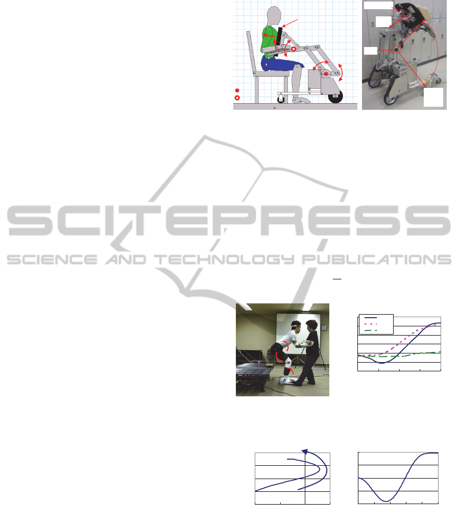
3 ASSISTANCE CONTROL
3.1 System Overview
Fig. 5(a) shows our proposed assistance robot. The
system consists of a support pad with three DOF and
the walker. The support pad is activated by our new
assistance manipulator, which has four parallel
linkages (Chugo et al., 2012). The patient leans on
the support pad and grasps the armrest while
standing with assistance (see Fig. 1(b)). In general,
fear of falling forward during the standing motion
reduces elderly patients’ standing ability (Maki et
al., 1991). With the proposed scheme, patients can
easily maintain their posture during the standing
motion without the fear of falling forward.
Fig. 5(b) shows the prototype of the proposed
robot. The prototype is able to lift patients up to 180-
cm tall and weighing up to 150 kg. Furthermore,
because of its actuated wheels, the prototype can
assist patients walk. To measure a patient’s posture,
the prototype has a force sensor and a laser range
finder in its body (see Fig. 5(b)).
Our physical activity estimation scheme, which
is proposed in the previous section, requires real-
time data regarding its assistance force and the
patient’s posture. To measure its assistance force,
our support pad has two force sensors on its body
that measure
pad
F
and
armrest
F
(see Fig. 5(b)). To
measure the patient’s posture, we use a laser range
finder; thus, calibration or special markers are not
required to be stuck on the patient.
3.2 Standing Motion as Recommended
by Nursing Specialists
Previous studies have proposed many types of
assisted standing. Based on her experience as a
nursing specialist, Kamiya proposed using the
Actuator1
Actuator2
Actuator3
Support Pad
(3DOF)
Actuator1 and 2
Actuator3
Motor Position
Fpad
Farmrest
Actuator1
Actuator2
Actuator3
Support Pad
(3DOF)
Actuator1 and 2
Actuator3
Motor Position
Fpad
Farmrest
Fpad
Sensing
area of
LRF
Force Sensor
LRF
Fpad
Sensing
area of
LRF
Force Sensor
LRF
(a) The robot’s actuators. (b) The robot’s sensors.
Figure 5: Prototype of the assistive robot.
patient’s maximum strength to stand, as shown in
Fig. 6. For effective standing assistance, we use a
control reference as shown in Fig. 7 (Kamiya, 2005).
Fig. 7(a) shows the support pad’s position tracks,
and Fig. 7(b) shows its angle tracks. The movement
pattern in Fig. 7(b) refers to a ratio of the standing
motion as determined by (8).
s
t
is the time required
to complete the standing operation, and
t
is the
present time.
s
t
t
s
ˆ
(8)
20
50
80
110
140
170
200
0 25 50 75 100
Movement Pattern (%)
Angle (deg
)
Trunk
Knee
Ankle
(a) Standing motion. (b) Angular value of each joint.
Figure 6: Standing motion recommended by nursing
specialists.
0.7
0.9
1.1
1.3
1.5
-0.2 -0.1 0 0.1
X-axis Position
(
m
)
Y-axis Position (m
)
50
60
70
80
90
0 20 40 60 80 100
Movement Pattern (%)
Angle (deg
)
(a) Position of P
pp
yx ,
(b) Inclination
p
Figure 7: Derived control references. The coordination is
defined in Fig. 1(a).
3.3 Assistance Control Scheme based
on the Physical Activity
For using the remaining physical strength of a
patient, our assistance system uses new control that
Ankle
Knee
Trunk
AssistiveRobotforStandingwithPhysicalActivityEstimationbasedonMuscleArrangementsofHumanLegs
39

combines damping control and position control
(Chugo et al., 2007). Damping control is suitable for
controlling objects with contact. From (2) and (3),
the assistance force
ypadyarmresty
ffF
in the lifting
direction will reduce the required traction of each
joint (
req
w
and
req
k
) because coefficients of
y
F
,
ws
xx
and
3
xx
w
in (2) and
kw
xx
in (3)
will be negative in usual standing posture.
Therefore, we can expect that the damping control
which increases
y
F
will reduce the required load of
a patient during standing motion.
In our proposed control algorithm, if the physical
activity of the patient is heavy, our system uses the
damping control for reducing the patient’s load. On
the other hand, if the activity of the patient is light,
our system uses the position control, which does not
assist the force, for using the remaining physical
strength of the patient. In our previous works, our
system uses a joint traction as an index of the
patient’s load for this algorithm (Chugo et al., 2012).
In this paper, we extended our assistance algorithm
using a proposed index of the patient’s physical
activity defined in (1).
3.3.1 Deriving the Reference
Before using the robot for assistance, we measure
the height and mass of each patient individually. The
length of each body segment is derived based on
Table 2 and used by the reference generator as it
derives the velocity control reference of each
actuator (No. 1, 2, and 3) (9) from the motion
reference (shown in Fig. 6) using the following
equation:
T
ref
i
ref
i
ref
i
ref
i
vsvv 1,,
ˆ
,,0 v
(9)
where
ref
i
v
is the velocity control reference
3,2,1i
, which is a function of the movement
pattern
s
ˆ
defined in (8). For more details regarding
the calculation process, please refer to our previous
work (Chugo et al., 2012).
3.3.2 Control Algorithm
Our system estimates the physical activity of the
patient using the proposed scheme (1) while
assisting patients as they stand. Based on this
estimation, the system selects a suitable control
scheme for damping and position controls. For this
to happen, the output of each actuator is derived
from
ref
iiyy
ref
ii
xxKFFBvv
0
(10)
where
ypadyarmresty
ffF
is the applied force to the
vertical direction on the support pad and armrest.
ref
i
x
is the angular position reference derived from
(9), and
i
x
is the actual angular position.
i
v
is the
updated reference that our system inputs to the
motor controller during the assisted standing motion.
0y
F
is the coefficient and force that the patient
applies to the support pad while he or she stands.
Using (10), our system can switch between the
position control mode and the damping control
mode.
3.3.3 Controller’s Parameter Coordination
B and K are constants that coordinate the ratio
between the damping and position controls. Our
system applies damping control when the maximum
estimated load of each joint
i
, which is defined in
(1), exceeds the threshold
%40
max
. i is the
identification character. (For example, for the knee
joint, i is k.) For applying damping control, the
coefficient B, which validates damping control, is
derived from
max
maxmax
0
i
ii
ifB
ifbB
(11)
Using this parameter coordination, our system
assists the patient with increased force when the
patient’s load is heavy. On the other hand, position
control is always useful because it helps the patient
maintain stable posture during the standing motion.
Thus, we set coefficient K, which validates position
control, as constant. In this study, the values b and K
are derived experimentally.
4 EXPERIMENTS
4.1 Experimental Setup
To verify the effectiveness of our proposed scheme,
eight subjects test the prototype robot, which is
implemented on the basis of the proposed estimation
scheme. Two subjects (Subjects A and B) are young
students and four subjects (Subjects C–F) are 54–72
years old with care levels of 1 or 2. Two subjects
(Subjects G and H) are hemiplegics aged 32 and 64
years. The young subjects (Subjects A and B) wear
special clothing designed to limit their motion in
order to simulate an elderly person’s limited
mobility (Takeda et al., 2001).
ICINCO2015-12thInternationalConferenceonInformaticsinControl,AutomationandRobotics
40
Unless otherwise noted, each subject tests the
following three cases five times. In Case 1, the robot
assists with the standing motion using only the
position control mode. Only subjects A and B test
this case because the robot does not assist with force
and the subject is required to stand using only their
own physical strength. In Case 2, the robot assists
the subject with the force control mode when the
subject’s physical activity exceeds their capability
threshold. In this case, the robot uses our proposed
load estimation scheme, and we set the threshold of
the subject’s capability as
%40
max
based on the
opinion of nursing specialists (Oshima et al., 1999).
In Case 3, the robot assists the subject with the force
control mode as necessary, similar to Case 2. The
difference between Cases 2 and 3 is that in Case 3,
the robot estimates the physical activity of the
subject using joint traction, as in our previous work
(Chugo et al., 2012). In this case, we set the
threshold of the subject’s capability as
kgNm
prev
5.0
max
based on previous research
(Omori et al., 2001).
In all cases, we use the standing motion
recommended by nursing specialists (Kamiya, 2005)
as specified in Section 3.2.
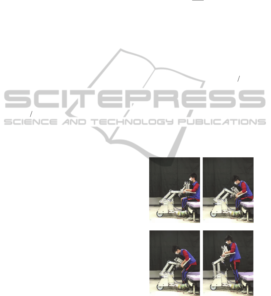
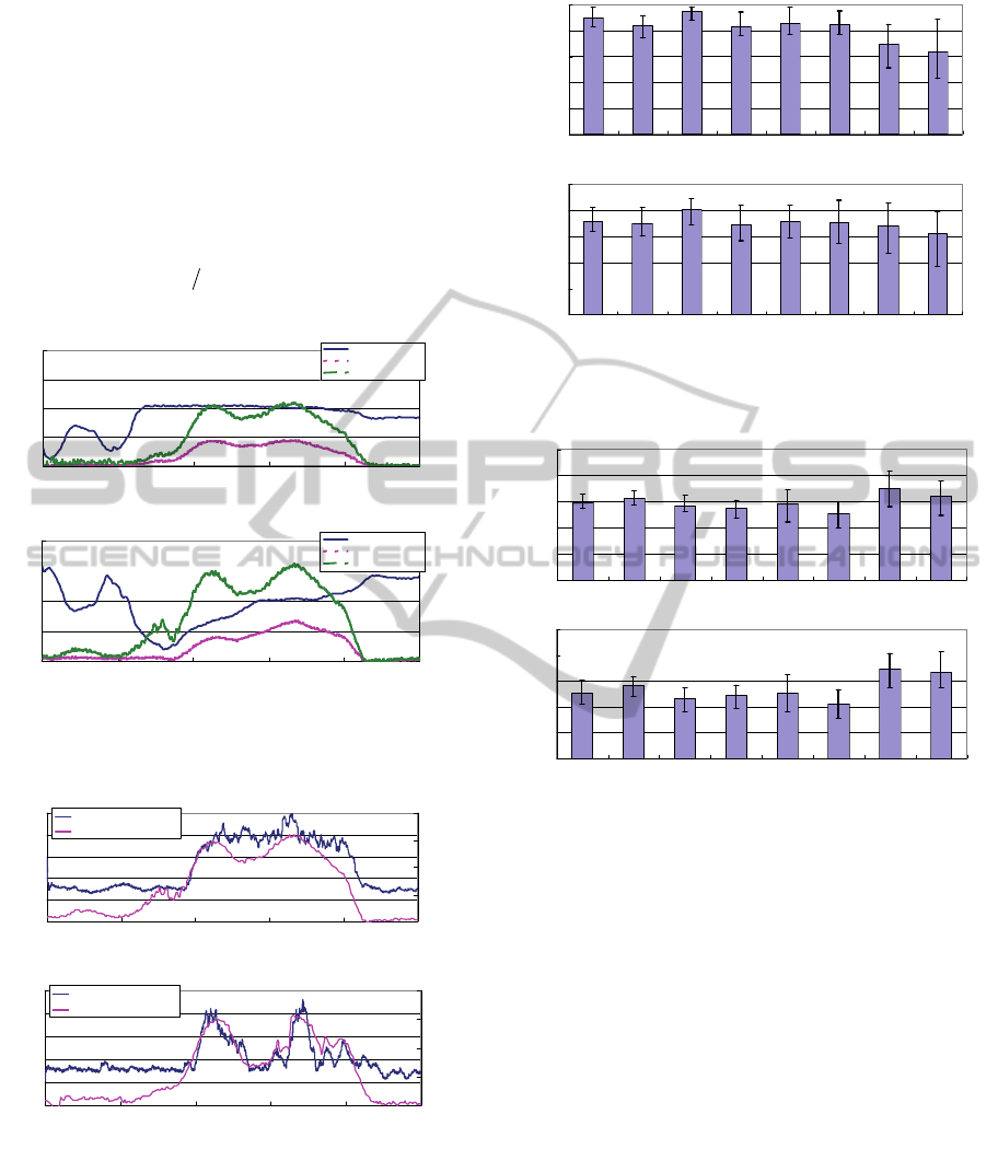
4.2 Experimental Results
The subject stands up as shown in Fig. 8. Fig. 9
shows the required traction
req
i
, the maximum
traction
max
i
(defined in (2), (3), (6), and (7)), and
the estimated physical activity of the subject
i
(defined in (1)) for each joint. As Fig. 8 shows, there
are different tendencies between
max
i
and
i
. The
estimated load
i
increases—especially at 40–75%
movement in a knee joint, around which time the
subject lifts their upper body and their load tends to
be heavy. This result is similar to the experiences of
nursing specialists (Nuzik et al., 1986).
Furthermore, Fig. 10 shows the EMG data of a
vastus lateralis (VAS) muscle that is normalized by
maximum voluntary contraction. This data reflects
the activity of the knee joint. The activity of the
VAS muscle in Fig. 10(a) has the same tendency as
our proposed load estimation index. In Fig. 10(b),
the estimated load exceeds the threshold
(
%40
max
), and our robot assists with force for
the standing motion. Therefore, the load of the
subject decreases during the knees’ 40–75%
movement. These results show that our proposed
load estimation scheme is effective.
Fig. 11 shows the ratio
which shows the correct
answer rate of the estimated physical activity from
(12).
s
match
t
t
(12)
where
s
t
is the time required to complete the
standing operation and
match
t
is the time when the
estimated physical activity exceeds the threshold
%40
max
and the measured muscle activity
exceeds 40%, too.
In Case 2 (Fig. 11(a)), our system uses the
proposed activity ratio
%40
max
as an index of
high physical activity; in Case 3 (Fig. 11(b)), our
system uses joint traction
kgNm
prev
5.0
max
as the
index. These results show that our proposed physical
activity estimation scheme (Case 2) is more accurate
than the previous index, which uses joint traction
(Case 3). Two subjects (Subjects G and H) are
hemiplegics and the estimation results for both cases
are inaccurate because their standing motions were
different from the motion recommended by nursing
specialists (Kamiya, 2005); therefore, different
muscles may be used when they stand up. Future
work will discuss the muscle model for hemiplegics.
(a) 0[%] (b) 30[%]
(c) 60[%] (d) 100[%]
Figure 8: Standing motion with our assistance robot (Case
1, Subject A).
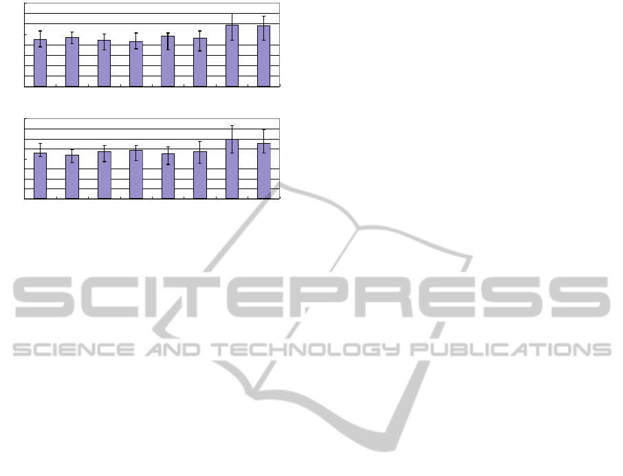
Using the estimated physical activity of the
subject, our robot assists with force control only
when necessary. As a result, Fig. 12 shows the
AssistiveRobotforStandingwithPhysicalActivityEstimationbasedonMuscleArrangementsofHumanLegs
41
maximum traction output
req
knee
(peak load) which the
subject is required to output for standing completely
and Fig. 13 shows the required output power for one
standing motion of a knee joint. From Fig. 12(a) and
(b), we see that the workload in Case 2 is larger than
that in Case 3, which means that the subject uses
more physical strength with our proposed load
estimation (Case 2). On the other hand, from Fig.
13(a) and (b), we see that the peak load is almost the
same and does not exceed the capability of the
subject,
kgNm
prev
5.0
max
, which means that our
robot assists with enough force when necessary.
0
0.5
1
1.5
2
0 20406080100
Movement Pattern (%)
Traction (Nm/kg)
0
20
40
60
80
Activity Ratio (%)
Maximum Traction
Required Traction
Physical Activity
(a) A waist joint
0
0.5
1
1.5
2
0 20 40 60 80 100
Movement Pattern (%)
Traction (Nm/kg)
0
20
40
60
80
Activity Ratio (%)
Maximum Traction
Required Traction
Physical Activity
(b) A knee joint
Figure 9: A required traction, a maximum traction, and the
estimated physical activity. (Case 1, Subject A).
0
20
40
60
80
100
0 20406080100
Movement Pattern [%]
EMG Ratio [%]
0
20
40
60
80
Activity Ratio [%
]
EMG-MVC
Estimated Physical Activity
(a) Case1 (Without a force assistance)
0
20
40
60
80
100
0 20406080100
Movement Pattern [%]
EMG Ratio [%]
0
20
40
60
80
Activity Ratio [%
]
EMG- MVC
Estimated Physical Activity
(b) Case2 (With a force assistance)
Figure 10: The estimated physical activity and the
measured muscle activity during a standing motion.
(Subject A).
These results show that our proposed load
estimation allows the robot to assist with standing in
such a way that the subject’s remaining physical
strength is used as much as possible.
0
20
40
60
80
100
Subject A Subject B Subject C Subject D Subject E Subject F Subject G Subject H
Estimation Ratio [%
]
(a) Case2 (with proposed estimation)
0
20
40
60
80
100
Subject A Subject B Subject C Subject D Subject E Subject F Subject G Subject H
Estimation Ratio [%
]
(b) Case 3 (with previous scheme)
Figure 11: Ratio of the estimated physical activity and the
measured muscle activity.
0
10
20
30
40
50
Subject A Subject B Subject C Subject D Subject E Subject F Subject G Subject H
Workload [Ws]
(a) Case2 (with proposed estimation)
0
10
20
30
40
50
Subject A Subject B Subject C Subject D Subject E Subject F Subject G Subject H
Workload [Ws]
(b) Case 3 (with previous scheme)
Figure 12: Workload of the knee joint.
5 CONCLUSIONS
This paper proposes both a physical activity
estimation scheme that considers muscle
arrangements and a novel assistance system that uses
those estimated results to take advantage of the
patient’s remaining physical strength in such a way
that the patient’s muscular strength will not decline
over time. By using our proposed scheme, our
system can reduce a patient’s load when the
patient’s posture is such that it is difficult to use any
of the patient’s own physical strength.
In our system, the subject is required to set
parameters, such as a cross-sectional area of each
muscle. Previous researchers have proposed a
derivation method of these values using easy
gymnastics (Oshima et al., 1999). We plan to
develop an automatic individual parameter
derivation scheme in future work.
ICINCO2015-12thInternationalConferenceonInformaticsinControl,AutomationandRobotics
42
0
0.1
0.2
0.3
0.4
0.5
0.6
0.7
0.8
Subject A Subject B Subject C Subject D Subject E Subject F Subject G Subject H
Peakload [Nm/kg
]
(a) Case2 (with proposed estimation)
0
0.1
0.2
0.3
0.4
0.5
0.6
0.7
0.8
Subject A Subject B Subject C Subject D Subject E Subject F Subject G Subject H
Peakload [Nm/kg
]
(b) Case 3 (with previous scheme)
Figure 13: Peakload of the knee joint.
ACKNOWLEDGEMENTS
This research is supported in part by Grant-in-Aid
for Scientific Research C (25350693) from Japan
Society for the Promotion of Science (JSPS).
REFERENCES
N. B. Alexander, A. B. Schultz and D. N. Warwick, 1991.
Rising From a Chair: Effects of Age and Functional Ability
on Performance Biomechanics.
In J. of Geometry:
MEDICAL SCIENCES, Vol.46, No.3, M91-98.
M. A. Hughes, M. L. Schenkman, 1996. Chair rise
strategy in the functionally impaired elderly. In J. of
Rehabilitation Research and Development, Vol.33,
No.4, pp.409-412.
Cabinet Office, Government of Japan, 2011. KOUREISHA
HAKUSHO (The whitepaper on the aged society),
ISBN: 4904681010, pp.25, (in Japanese).
K. Nagai, I. Nakanishi and H. Hanabusa, 2003. Assistance
of self-transfer of patients using a power-assisting
device. In Proc. of the IEEE Int. Conf. on Robotics
and Automation, pp.4008-4015.
A. Funakubo, H. Tanishiro and Y. Fukui, 2001. Power
Assist System for Transfer Aid. In J. of the Society of
Instrument and Control Engineers, Vol.40, No.5,
pp.391-395.
M. Hirvensalo, T. Rantanen and E. Heikkinen, 2000.
Mobility difficulties and physical activity as predictors
of morality and loss of independence in the
community-living older population. In J. of the
American Geriatric Society, Vol.48, pp.493-498.
D. Chugo, Y. Morita, Y. Sakaida, S. Yokota, H.
Kobayashi, H. Hashimoto and K. Takase, 2012.
Standing Assistance Control using a Physical Strength
of a Patient with Load Estimation. In Proc. of 21st
IEEE Int. Symp. on Robot and Human Interactive
Communication, pp.234-239.
S. Nuzik, R. Lamb, A. Vansant and S. Hirt, 1986. Sit-to-
Stand Movement Pattern, A kinematic Study. In
Physical Therapy, Vol.66, No.11, pp.1708-1713.
T. Hatsukari, S. Kuroko, N. Miyake, R. Kawazoe, J.
Higuchi, Y. Hirata and K. Kosuge, 2009. Self-help
Standing-up Method Based on Quasi-static Motion. In
Proc. of the IEEE Int. Conf. on Robotics and
Biomimetics, pp.342-347.
I. Nishida, M. Maeda, T. Kawano and K, Shirase, 2011.
Estimation Method of Muscle Forces of Lower Limb
Considering the Role of Antagonistic Muscles and
Biarticular Muscles –Estimation of Muscle Forces of
Lower Limb during Vertical Jumping–. In J. of Japan
Ergonomics Society, Vol.47, No.6, pp.244-251.
H. Okada, M. Ae, N. Fujii and Y. Morioka, 1996. Body
Segment Inertia Properties of Japanese Elderly. In
Biomechanisms, No.13, pp.125-139.
T. Oshima, T. Fujikawa and M. Kumamoto, 1999.
Functional Evaluation of Effective Muscle Strength
Based on a Muscle Coordinate System Consisted of
Bi-articular and Mono-articular Muscles –Contractile
Forces and Output Forces of Human Limbs–. In J. of
Precision Engineering, Vol.65, No.12, pp.1772-1777.
S. A. Spector, P. F. Gardiner, R. F. Zernicke, R. R. Roy
and V. R. Edgerton, 1980. Muscle architecture and
force-velocity characteristics of cat soleus and medial
gastrocnemius: implications for neural control. In J. of
Neuro-physiol, Vol.44, pp.951-960.
M. G. Hoy, F. E. Zajac, M. E. Gordon, 1990. A
Musculoskeletal Model of the Human Lower
Extremity: The Effect of Muscle, Tendon, and
Moment Arm on the Moment-Angle Relationship of
Musculotendon Actuators at the Hip, Knee, and Ankle.
In J. of Biomechanics, Vol.23, No.2, pp.157-169.
E. Maki, P. J. Holliday and A. K. Topper, 1991. Fear of
falling and postural performance in the elderly. In J. of
Gerontology, Vol.46, No.4, pp. 123-131.
K. Kamiya, 2005. Development and evaluation of life
support technology in nursing. In Proc. of 7th RACE
Symp., Research into Intelligent Artifacts for the
Generalization of Engineering, pp.116-121.
D. Chugo, W. Matsuoka, J. Songmin and K. Takase, 2007.
Rehabilitation Walker with Standing-Assistance
Device. In J. of Robotics and Mechatoronics, Vol.19,
No.6, pp. 604-611.
K. Takeda, Y. Kanemitsu and Y. Futoyu, 2001.
Understanding the Problem of the Elderly through a
Simulation Experience – Difference in the Effect
between Before and After Clinical Practice –. In
Kawasaki Medical Welfare J. Vol.11, No.1, pp.64-73.
K. Omori, Y. Yamazaki, H. Yokoyama, U. Aoki, M.
Kasahara, K. Hiraki, 2001. The relationship between
strength in the lower extremity and the ability to stand
up from a chair in elderly inpatients. In Sogo
Rehabilitation. Vol.30, No.2, pp.167-171.
AssistiveRobotforStandingwithPhysicalActivityEstimationbasedonMuscleArrangementsofHumanLegs
43
