
Visual Servoing-based Registration of Multimodal Images
M. Ourak
1
, B. Tamadazte
1
, N. Andreff
1
and E. Marchand
2
1
FEMTO-ST Institute, AS2M Department, Universit
´
e de Franche-Comt
´
e/CNRS/ENSMM, 24 rue Savary, Besano¸n, France
2
Universit
´
e de Rennes 1, IRISA, Rennes, France
Keywords:
Visual Servoing, Mutual Information, Nelder-Mead Simplex.
Abstract:
This paper deals with mutual information-based numerical and physical registration of white light images vs.
fluorescence images for microrobotic laser microphonosurgery of the vocal folds. More precisely, it presents
two techniques: a numerical registration of multimodal images and a vision feedback control for positioning
an endoscope with regards to a preoperative image (fluorescence image). Nelder-Mead Simplex for nonlinear
optimization is used to minimize the cost-function. The proposed methods are successfully validated in an
experimental set-up using preoperative fluorescence images and real-time white light images of the vocal
folds.
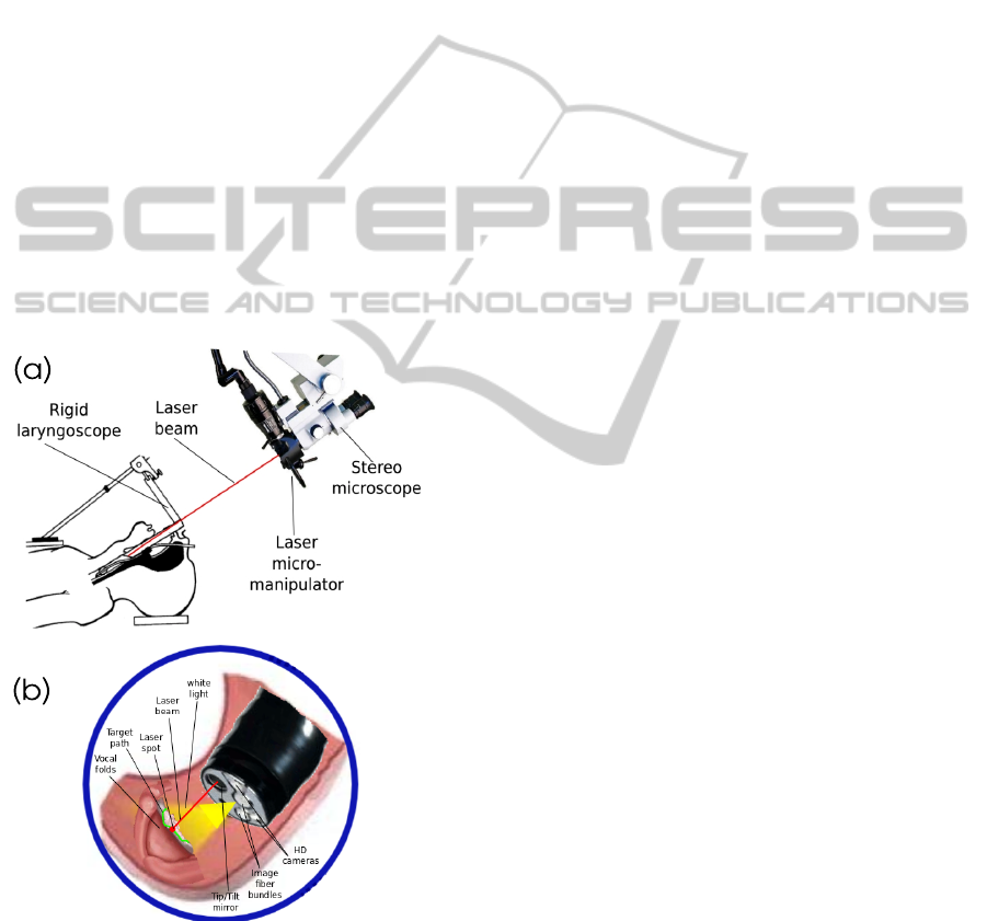
1 INTRODUCTION
Direct visualization of the larynx and the trachea is
often used for the diagnosis but also in surgical in-
tervention (Jackel et al., 2013). The most successful
robotic system for the vocal folds surgery is certainly
the suspension lryngoscope (Figure 1(a)). It consists
of a straight-rigid laryngoscope, a stereomicroscope,
a laser source, and a controlled device based on a foot-
pedal activating the laser (Eckel et al., 2003). This
system is largely deployed in hospitals but it features
many drawbacks: i) extreme extension of the patient’s
neck; ii) poor ergonomics of the operating setup; iii)
considerable skills and expertise required for the clin-
ician; and iv) lack of precision.
Alternative approaches are under investiga-
tion: the use of the HARP (Highly Articulated
Robotic Probe) highly flexible robot for conventional
surgery (Degani et al., 2006) or the use of an endo-
scopic laser micromanipulator (Tamadazte and Andr-
eff, 2014) (Figure 1(b)). In both cases, surgery can
be preceded by a diagnosis using fluorescence imag-
ing (Sevick-Muraca, 2004). For this, the fluorescence
based diagnosis is done a few days before surgery in-
tervention. Therefore, during a surgical intervention
the fluorescence diagnosis image must be registered
to the real-time white light images grabbed by the en-
doscopic system in order to define the incision path
pour the laser ablation or resection. The Registration
can be done either numerically or by physically mov-
ing the endoscope to the place where the fluorescence
image was grabbed few days ago.
In this paper, our aim is to control a robot based
on direct visual servoing, using image information
coming from light white and fluorescence sensors.
However, this control needs to be done without a pri-
ory model of the robot and the camera. Indeed, ap-
proaches have been implemented which are mainly
based on the use of the image global information
(gradient (Marchand and Collewet, 2010), photome-
try (Collewet and Marchand, 2011) or mutual infor-
mation (Dame and Marchand, 2011)). The use of mu-
tual information (MI) in visual servoing problems has
proved to be especially effective in the case of mul-
timodal and less contrasted images (Dame and Marc-
hand, 2009).In fact, these control techniques assume
that the kinematic model of the robot and the cam-
era intrinsic parameters are at least partially known,
but would fail if the system parameters were fully un-
known. In addition to the constraint that the initial po-
sition cannot be very distant from the desired position
to totally ensure convergence. Therefore, it was pro-
posed to use the Simplex method (Nelder and Mead,
1965) instead of gradient (which requires at least a
rough calibration of the camera and a computation of
the camera/robot transformation) as in (Miura et al.,
2005) where the geometrical visual features are used
to design the controller.
Furthermore, in the surgical robotics context, it
is preferable to free ourselves from any calibration
procedure (camera, robot or robot/camera system) for
several reasons:
44
Ourak M., Tamadazte B., Andreff N. and Marchand E..
Visual Servoing-based Registration of Multimodal Images.
DOI: 10.5220/0005528900440051
In Proceedings of the 12th International Conference on Informatics in Control, Automation and Robotics (ICINCO-2015), pages 44-51
ISBN: 978-989-758-123-6
Copyright
c
2015 SCITEPRESS (Science and Technology Publications, Lda.)
• calibration procedures is often difficult to perform
especially by non-specialist operators i.e., clini-
cians;
• surgeons entering in the operation room are per-
fectly sterilized to avoid any risk of contamina-
tion, and then it is highly recommended to limit
the manipulation of the different devices inside
the operating room.
For these reasons, we opted for uncalibrated and
model-free multimodal registration and visual servo-
ing schemes using the MI as a global visual feature
and a Simplex optimization method. This means it is
not necessary to compute the interaction matrix (Ja-
cobian image); the kinematic model of the robot may
be totally unknown without any constraint in the ini-
tial position of the robot with respect to its desired
position.
This paper is structured as follows: Section 2
gives the basics of MI. Section 3 presents the Sim-
plex method. Section 4 describes the multimodal reg-
istration and the visual servoing achievement. Finally,
Section 5 deals with the validation results.
Figure 1: (a) The current laser phonosurgery system and (b)
The targeted system.
2 MI AND REGISTRATION
In the literature, multimodal images registration has
been widely discussed. Zitova et al. (Zitov
´
a and
Flusser, 2003) classified registration techniques for
medical applications into two main categories: area-
based and features-based methods. In these cases, the
registration process follows mainly four steps: fea-
ture detection, feature matching, transformation esti-
mation, and image resampling. As previously stated,
our approach is based mutual information rather than
geometrical visual features. Therefore, the most crit-
ical steps (feature detection and matching) of a con-
ventional registration method are removed. Instead,
from the joint and marginal entropy of two images, it
is possible to compute their similarities. This means
that is the higher the MI, the more the images are
aligned (Dame and Marchand, 2009).
2.1 Mutual Information in the Image
MI is based on the measure of information, commonly
called entropy, in 1D signal. By extension, the en-
tropy expression in an image I is given by
H(I) = −
N
I
∑
i=0
p
I
(i)log
2
(p
I
(i)) (1)
where H(I) represents the marginal entropy also
called Shannon entropy of an image I, i ∈ [0, N
I
] (with
N
I
= 255) defines a possible gray value of an image
pixel, and p
I
is the probability distribution function
also called marginal probability of i. This can be esti-
mated using the normalized histogram of I.
Moreover, the entropy between two images I
1
and
I
2
is known as joint entropy H(I
1
,I
2
). It is defined as
the joint variability of both images
H(I
1
,I
2
) = −
N
I
1
∑
i=0
N
I
2
∑
j=0
p
I
1
I
2
(i, j)log
2
(p
I
1
I
2
(i, j)) (2)
where i and j are the pixels intensities of the two
images I
1
and I
2
respectively, p
I
1
I
2
(i, j) is the joint
probability for each pixel value. The joint probabil-
ity is accessible by computing the N
I
1
+ 1 × N
I
2
+
1 × N
bin
+ 1 joint histogram which is built with two
axes defining the bin-size representation of the image
gray levels and an axis defining the number of occur-
rences between I
1
and I
2
.
From (1) and (2), the MI contained in I
1
and I
2
is
defined as
MI(I
1
,I
2
) = H(I
1
) + H(I
2
) − H(I
1
,I
2
) (3)
and can be expressed using the marginal probability
p
I
and joint probability p
I
1
I
2
(i, j), by replacing (1)
VisualServoing-basedRegistrationofMultimodalImages
45

and (2) in (3) with some mathematical manipulations
MI(I
1
,I
2
) =
∑
i, j
p
I
1
,I
2
(i, j)log
p
rI
1
I
2
(i, j)
p
I
1
(i)p
I
2
( j)
(4)
which has to be maximized.
In practice, cost-function computed using (4)
shows the presence of noise in the MI. This creates
more or less important local maxima which compli-
cate the optimization process (Dame and Marchand,
2009). To reduce the joint histogram space as well as
MI noise and thereby local maxima (at least for the
less significant local maxima), Dawson et al. (Dow-
son and Bowden, 2006) have proposed to use the in-
Parzen windowing formulation in the MI computation
I
b1
(k) = I
1
(k)
N
c
r
max
and I
b2
(k) = I
2
(k)
N
c
t
max
(5)
where t
max
= r
max
= 255 and N
c
the new bin-size of
the joint histogram and I
b1
,I
b2
is the new gray level
value of I
1
and I
2
, respectively.
In addition to the resampling of the joint his-
togram, it is advisable to introduce a filtering method
based on B-splines interpolation in order to further
smooth the MI cost-function. Thus, the abrupt change
(mainly due to the fact that we use multimodal im-
ages) in the cost-function creating local maxima are
flattened in order to reduce again these irregularities.
In our case, we opted for a third-order interpolation
ψ which presents a good balance between smoothing
quality and time computation. Thereby, both marginal
and joint probabilities become
p
I
b1
I
b2
(i, j) =
1
N
k
∑
k
ψ(i − I
b1
(k)) ψ
j − I
b2
(k)
(6)
p
I
b1
(i) =
1
N
k
∑
k
ψ(i − I
b1
(k, x)) (7)
p
I
b2
( j) =
1
N
k
∑
k
ψ( j − I
b2
(k)) (8)
with N
k
is the number of pixels in the new images I
b1
and I
b2
and ψ is the used B-spline function.
3 SIMPLEX-BASED
REGISTRATION
This section deals with the method for solving the MI
maximization problem. However, before describing
the chosen optimization approach among the many
existing ones (Kelley, 1999) to solve this problem, it is
necessary to know the exact shape of the cost-function
in the case of bimodal images (fluorescence vs. white
light) of the vocal cords.
In practice, rather than maximizing MI, we mini-
mize the cost-function
f(r) = −MI[I
b1
(r),I
b2
] (9)
Because the MI depends on a translation of both
images, the problem to solve is
b
r = arg min
r∈SE(3)
f(r) (10)
where r the camera pose with respect to world refer-
ence frame.
3.1 Cost-function Shape
Figure 2 shows the computed cost-function in nomi-
nal conditions (i.e., the high definition images shown
in Figure 7). It has a global convex shape but still has
many irregularities. Consequently, derivative based
methods such as gradient descent could not neces-
sarily guarantee convergence. Thereby, an uncon-
strained optimization technique was chosen to tackle
this problem, i.e., a modified Simplex algorithm.
0
10
20
30
0
5
10
15
−0.5
−0.45
−0.4
−0.35
−0.3
−0.25
−0.2
−0.15
x−displacement (mm)
y−displacement (mm)
Cost
Figure 2: MI cost-function in nominal conditions (represen-
tation of -MI).
3.2 Modified Simplex Algorithm
r
G
g
g
(B)
(C)
(A)
g
(D)
r
W
r
B
r
R
r
G
r
W
r
B
r
R
r
E
r
G
r
W
r
B
r
B
r
W
r
G
r
R
r
G'
r
W'
r
C
r
R
r
C
Figure 3: Example of the Simplex steps: (A) reflection, (B)
expansion, (C) contraction, and (D) shrinkage.
The Nelder-Mead Simplex algorithm (Nelder and
Mead, 1965) roughly work as follows.
ICINCO2015-12thInternationalConferenceonInformaticsinControl,AutomationandRobotics
46
A Simplex shape S defined by vertices r
1
∈ SE(3)
to r
k+1
∈ SE(3) with k = dim(6) is iteratively up-
dated until convergence using four operators: reflec-
tion, contraction, expansion, and shrinkage (see Fig-
ure 3). Thus, the Simplex S performs the fourth steps
as follows
re f lection : r
R
= (1 − α)g + αr
W
(11)
where r
R
the reflection vertex, α the reflection coeffi-
cient and g the centroid between r
G
and r
B
.
expansion : r
E
= (1 − γ)g + γr
R
(12)
where r
E
the expansion vertex and γ the expansion
coefficient, and
contraction : r
C
= (1 − β)g + βr
W
(13)
where r
C
the contraction vertex, and β the contraction
coefficient.
shrinkage : r
0
G
= (r
G
+ r
B
)/2
r
0
W
= (r
W
+ r
B
)/2
(14)
where the vertices are updated as: r
G
= r
0
G
and r
W
=
r
0
W
.
Finally, the algorithm ends
when val(S) ≤ ε where val(S) =
max
dist(r
W
, r
B
), dist(r
W
, r
G
), dist(r
G
, r
B
)
,
ε is a predefined eligible small distance and dist is
the distance between two vertices.
By convention, the vertices are ordered as
f (r
1
) ≤ f (r
2
) ≤ ··· ≤ f (r
k+1
) (15)
where r
1
= the best vertex
r
k+1
= the worst vertex
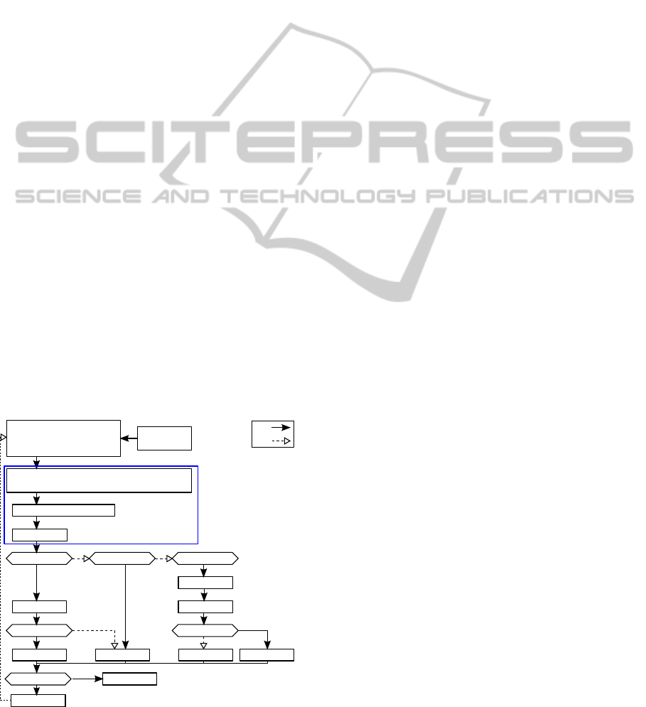
Initialize
simplex
Re-order
r
W
,r
G
and r
B
such as
f(r
W
) < f(r
G
) < f(r
W
)
Extract vector r
S
r
S
: diagonal elements of a matrix vertices r
Quasi gradients of r
S
Reflection
f(r
R
) < f(r
B
) f(r
R
) < f(r
G
) f(r
R
) < f(r
W
)
r
W
= r
R
Contraction
f(r
C
) < f(r
W
)
r
W
= r
C
Shrink
r
W
= r
R
r
W
= r
E
f(r
E
) < f(r
W
)
Expansion
vol or N
iter
N
max
Exit
Improve simplex with
quasi gradient
Yes
No
r
k
= r
B
≤
�
≤
Figure 4: Modified Simplex Algorithm.
The minimization of the cost-function using the
Simplex algorithm is shown in Figure 4. In our
case, the Simplex was modified, by introducing the
quasi-gradient convergence instead of reflection stage
method (Pham and Wilamowskial, 2011), in order to
improve the convergence direction of f (without get-
ting trapped in local minima) when the controller ap-
proaches the desired position. This combination of
an unconstrained and nonlinear method and a quasi-
gradient technique allows a higher rate, faster and
smooth convergence speed. This returns to combine
the advantages of a Simplex and gradient-based opti-
mization methods.
Therefore, (11) is replaced with
r
R
= r
B
− αQ (16)
where Q the quasi-gradient vector based on the diag-
onal elements of vertices matrix r and k other points.
4 REGISTRATION VS. VISUAL
SERVOING
4.1 Image Transformation
First, the considered registration is defined as a rigid
transformation between two images. Let us as-
sume the transformation
b
r ∈ ℜ
3
× SO(1) between the
white light image I
b1
and the fluorescence image I
b2
.
Thereby, this transformation can be estimated by min-
imizing the value of MI(I
b1
,I
b2
).
b
r = argmin −MI[I
b1
(r),I
b2
] | r : ℜ
3
× SO(1) (17)
where r a possible rigid transformation. Note that in
our case, r includes the planar xyθ and z transforma-
tions.
The process allowing to carry out this registration
is operating as follows: acquisition of both white light
image I
b1
and fluorescence image I
b2
then computing
MI(I
b1
, I
b2
). The obtained transformation r from the
first optimization is then applied to synthesize a new
image I
b1
r
from the image I
b1
. These steps are re-
peated until the predefined stop criterion is reached.
4.2 Visual Servoing
Now, it is possible to define a visual servoing control
law without any explicit interaction matrix (Jacobian
image) or kinematic model robot. Let us assume that
we have the cost-function shown in Figure 2, then our
objective is to find the global minimum
b
r = arg min
r∈SE(3)
−MI [I
b1
(r),I
b2
] (18)
VisualServoing-basedRegistrationofMultimodalImages
47
Note that in our experimental validation, we use
a lab-made microrobotic cell having only 3 DOF
xyθ. This limits, in our case, the transformation to
r ∈ ℜ
2
× S0(1).
A first way to move the robot so that the current
(smoothed) image I
b1
superimpose onto the desired
fluorescence (smoothed) image I
b2
is to use the look-
than-move approach: let the Simplex method con-
verge then apply
b
r
−1
to the robot and start again (Fig-
ure 6). However, this requires a very fine tuning of the
Simplex algorithm. The chosen approach allows in-
terlacing the Simplex loop and the vision-based con-
trol loop. At each iteration n, the Simplex provides
r
n
B
, the best vertex so far, which is associated to the
best transformation
0
T
n
since the initialization. Thus,
applying directly the Simplex would require displac-
ing the robot by
n−1
T
n
=
0
T
−1
n−1
0
T
n
(19)
This displacement will not be applied to the complete
transformation
n−1
T
n
found, because that may have
the robot to take too large motion. Instead, we extract
the screw (δ,t) associated to
n−1
T
n
n−1
T
n
= e
[δ]
∧
t
0 0
!
(20)
and take only a fraction of it δ = λδ and t = λt, con-
verted to a damped velocity over the sample period T
s
which is ω = λδ/T
s
and v = λt/T
s
.
Applying this velocity to the robot requires to up-
date the Simplex vertex r
n
B
according to the current
(estimated) transformation (Figure 5).
r
n
B
⇔
0
T
n
update
=
0
T
n−1
e
[δ]
∧
t
0 0
!
(21)
This slows down the robot.
5 REAL-WORLD VALIDATION
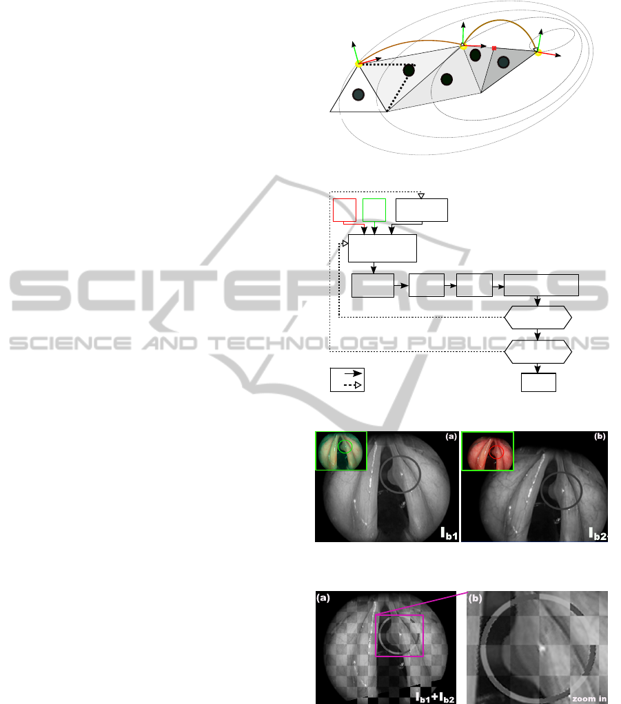
5.1 Numerical Registration Results
The proposed numerical registration method is vali-
dated using two vocal folds images: real fluorescence
and white light. These images taken from (Arens
et al., 2004) were acquired in two different points of
view with known pose as shown in Figure 7. It can be
highlighted that
b
r between I
b1
and I
b2
includes four
parameters (x, y, θ and zoom). To be more realistic
in our validation tests, we added a circular trajectory
(i.e., virtual incision mark done by a surgeon), to be
tracked by the surgical laser spot, in the fluorescence
1
2
3
R
0
R
n
0
T
n-1
n-1
T
n
X
des
4
R
n-1
5
Figure 5: Possible evolution of the Simplex.
Simplex
Initialization
- Value of vertices to reach all transf.
- Simplex parameters.
- Init one vertex with zero value.
Compute
transformation
r
B
- Simplex evolution.
- Virtual transf. in the current image (I
b1
)
- Resampling
Compute
velocity
Sent
velocity
Grab new white
light image ( )
Simplex
Stopping
criteria
I
b1
I
b2
Exit
Yes
No
I
b1
Update
r
B
Figure 6: MI-based visual servoing scheme.
Figure 7: (a) Fluorescence image I
b2
and (b) White light
image I
b1
.
Figure 8: Numerical registration results: (a) shows I
b1
inte-
grated in I
b2
, and (b) a zoom in of region of interest.
image delimiting the tumor (Figure 7). This path is
then by analyzing Figure 8(a), it can be underlined
the continuity of the combination I
b1
+ I
b2
which
explains the high accuracy of the registration method,
this is clearly visible on the zoom in the incision mark
(Figure 8(b)). For this example, the numerical values
are summarized in Table 1.
ICINCO2015-12thInternationalConferenceonInformaticsinControl,AutomationandRobotics
48
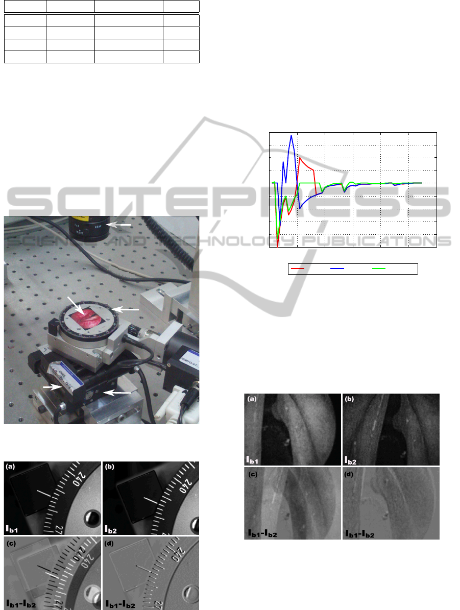
Table 1: Numerical values of
b
r,
b
z (1pix = 0.088mm).
DOF real pose obtained pose errors
x (mm) -8.000 -7.767 0.233
y (mm) -12.000 -12,059 0.059
θ (deg) 12.000 12.500 0.500
z 1.09 1.089 0.010
5.2 Visual Servoing Results
It is not yet possible to test our developments di-
rectly on true vocal folds using the developed flexible
laryngoscope by current lack of a technical solution
for fiber-based surgical laser and fiber-based imag-
ing system (this problem is being addressed through
the EU project µRALP: http://www.microralp.eu) (see
Figure 14). Therefore, a 3 DOF (xyθ) microrobotic
cell is used for the validation (Figure 9).
Camera
Vocal folds
photography
Ⲑ stage
x stage
y stage
Figure 9: Photography of the microrobotic cell.
Figure 10: MI-based visual servoing (white light images).
Firstly, the MI-based visual servoing is validated
on monomodal images in aim to verify the validity
of our controller. Figure 10 represents an example
of white light images registration in visual servoing
mode. More precisely, Figure 10(a) and (b) repre-
sent the initial and desired images, respectively. In
the same way, Figure 10(c) and (d) show the initial
and final error I
b1
- I
b2
. It can be noticed that the final
position of the positioning platform matches perfectly
with the desired position indicating the good accuracy
of our method.
0 10 20 30 40 50 60
−2500
−2000
−1500
−1000
−500
0
500
1000
1500
2000
Iterations
Velocities
White light vs. White light
V
x
[µm/sec] V
y
[ µm/sec]
V
θ
[µrad/sec]
Figure 11: Image velocities v
x
, v
y
and v
θ
vs. iterations i.
Figure 11 shows the evolution of the velocities v
x
,
v
y
and v
θ
in the different DOF versus number of it-
erations i. It can be underlined that the developed
controller converges with accuracy in fifty iterations
(each iteration takes about 0.5 second). Also, the
speed varies in the iteration 40 because the Simplex
after initialization found a new best minimum.
Figure 12: MI-based visual servoing (white light vs. fluo-
rescence images).
Secondly, vocal folds multimodal images are also
used to test the proposed controller. In this scenario,
the desired image is in fluorescence mode (prere-
corded image) and the current images are in white
VisualServoing-basedRegistrationofMultimodalImages
49
light mode as it would be in the surgical context. Fig-
ure 12(a) and (b) show the initial image I
b1
and the
desired image I
b2
, respectively. Figure 12(c) and (d)
illustrate the error I
b1
- I
b2
during the visual servo-
ing process. As shown in this figure, the controller
converges also to the desired position with a good
accuracy. Note that the image I
b1
- I
b2
is not com-
pletely gray (if two pixels are exactly the same, it is
assigned the gray value of 128 for a better visualiza-
tion of I
b1
− I
b2
), this is due to the fact that both im-
ages are acquired from two different modalities, then
the difference will never be zero (respectively 128 in
our case).
In the same manner, Figure 13 shows the evolu-
tion of the velocities v
x
, v
y
and v
θ
with respect number
of iterations i. It can be also underlined that the con-
troller converges with accuracy to the desired position
despite the large difference between I
b1
and I
b2
.
0 10 20 30 40 50 60
−4000
−3000
−2000
−1000
0
1000
2000
3000
4000
White light vs. Fluorescence
Iterations
Velocities
V
x
[µm/sec] V
y
[ µm/sec]
V
θ
[µrad/sec]
Figure 13: Image velocities v
x
, v
y
and v
θ
vs. iterations i.
Additional validation tests were performed to as-
sess the repeatability and behavior (convergence and
robustness) of the controller. Therefore, for each test,
the experimental conditions (lighting conditions, ini-
tial position and image quality) were deliberately al-
tered. Table 2 gives the results of a sample of these
experiments.
6 CONCLUSIONS
In this paper, a novel metric visual servoing-based on
MI has been presented. Unlike the traditional meth-
ods, the developed approach was based only on the
use of a modified Simplex optimization without any
knowledge of neither robot, camera models nor cam-
era/robot transformation. It has been shown that the
designed controller works even in the presence of
many local minima in the MI cost-function. Beside
this, the controller has shown good behavior in terms
of accuracy, repeatability and convergence.
Table 2: Repeatability test for visual servoing (x, y, and
error in mm, θ in
◦
) and t in seconds.
N
◦
DOF des. pos. ini. pos. error t
x 5.37 2.47 -0.33
1 y 2.94 0.66 0.37 25.2
θ -2.61 -8.43 2.51
x 4.02 -0.66 0.37
2 y -5.57 -5.05 1.45 36.5
θ 2.47 -5.05 2.41
x 6.05 3.14 0.16
3 y 1.47 0.21 0.88 49.2
θ -14.59 -24.19 0.64
x 4.09 2.1 0.17
4 y 2.12 0.44 0.4 36.3
θ 14.56 6.63 1.15
x 3 0.31 0.55
5 y 2.5 0.19 0.53 57.3
θ -4.81 14.53 0.83
Future work will be devoted to optimize the com-
putation time to reach the video rate and imple-
ment this approach in the developed laser vocal folds
surgery system shown in Figure 14. Also, we will dis-
cuss the validation of the controller in SE(3) using a
6 DOF robot.
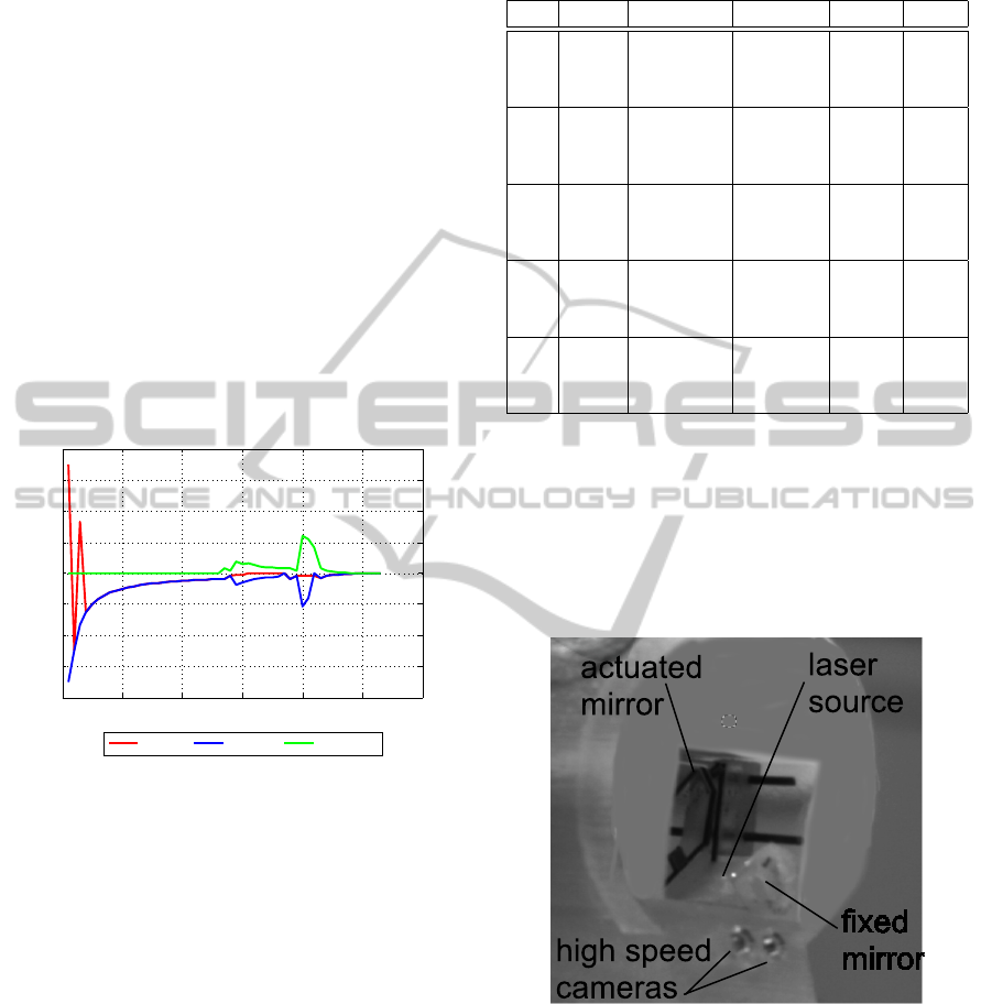
Figure 14: Photography of the developed endoscopy tip.
ACKNOWLEDGEMENTS
This work was supported by French ANR NEMRO
no ANR-14-CE17-0013-001, and by µRALP, the
EC FP7 ICT Collaborative Project no. 288663
(http://www.microralp.eu), and by ACTION, the
French ANR Labex no. ANR-11-LABX-0001-01
(http://www.labex-action.fr).
ICINCO2015-12thInternationalConferenceonInformaticsinControl,AutomationandRobotics
50

REFERENCES
Arens, C., Dreyer, T., and Glanz, H. Malzahn, K. (2004).
Indirect autofluorescence laryngoscopy in the diagno-
sis of laryngeal cancer and its precursor lesions. Eu-
ropean Archives of Oto-Rhino-Laryngology and Head
& Neck, 261(2):71–76.
Collewet, C. and Marchand, E. (2011). Photometric visual
servoing. IEEE Trans. on Robotics, 27(4):828–834.
Dame, A. and Marchand, E. (2009). Entropy-based visual
servoing. In IEEE Int. Conf. on Robotics and Automa-
tion, pages 707–713, Kobe, Japan.
Dame, A. and Marchand, E. (2011). Mutual information-
based visual servoing. IEEE Trans. on Robotics,
27(5):958–969.
Degani, A., Choset, H., Wolf, A., and Zenati, M. A. (2006).
Highly articulated robotic probe for minimally inva-
sive surgery. In Robotics and Automation, 2006. ICRA
2006. Proceedings 2006 IEEE International Confer-
ence on, pages 4167–4172. IEEE.
Dowson, N. and Bowden, R. (2006). A unifying framework
for mutual information methods for use in non-linear
optimisation. In Computer Vision ECCV, volume
3951 of Lecture Notes in Computer Science, pages
365–378. Springer Berlin Heidelberg.
Eckel, H., Berendes, S., Damm, M., and Klusmann, J.
(2003). Suspension laryngoscopy for endotracheal
stenting. Laryngoscope, 113:11–15.
Jackel, M., Martin, A., and Steine, W. (2013). Twenty-five
years experience with laser surgery for head and neck
tumors. volume 264 of European Archives of Oto-
Rhino-Laryngology, pages 577–585.
Kelley, C. (1999). Iterative Methods for Optimization.
Frontiers in Applied Mathematics 18.
Marchand, E. and Collewet, C. (2010). Using image gradi-
ent as a visual feature for visual servoing. In IEEE/RSJ
Int. Conf. on Intelligent Robots and Systems, IROS’10,
pages 5687–5692, Taipei, Taiwan.
Miura, K., Hashimoto, K., Gangloff, J., and de Mathelin,
M. (2005). Visual servoing without jacobian using
modified simplex optimization. In Robotics and Au-
tomation, 2005. ICRA 2005. Proceedings of the 2005
IEEE International Conference on, pages 3504–3509.
IEEE.
Nelder, A. and Mead, R. (1965). A simplex method for
function minimization. ComputerJournal, 7:308–313.
Pham, N. and Wilamowskial, B. (2011). Improved nelder
mead’s simplex method and applications. Journal of
computing, 3(3):55–63.
Sevick-Muraca, E. (2004). Fluorescence-enhanced opti-
cal imaging and tomography for cancer diagnostics.
In Biomedical Imaging: Nano to Macro, 2004. IEEE
International Symposium on, volume 2, pages 1482–
1485.
Tamadazte, B. and Andreff, N. (2014). Weakly calibrated
stereoscopic visual servoing for laser steering: Appli-
cation to phonomicrosurgery. In IROS, pages 743–
748.
Zitov
´
a, B. and Flusser, J. (2003). Image registration
methods: a survey. Image and Vision Computing,
21(11):977–1000.
VisualServoing-basedRegistrationofMultimodalImages
51
