
A New Energetically Optimized Power Supply System for a Mobile
Robot Platform, using Ultracapacitors and Batteries to Ensure Both
Ultra-fast Charging and Autonomy
Carlos Arantes
1
, João Sena Esteves
2
and João Sepúlveda
2
1
Department of Industrial Electronics, University of Minho, Campus of Azurém, 4800-058 Guimarães, Portugal
2
Centre Algoritmi, Department of Industrial Electronics, University of Minho, Campus of Azurém,
4800-058 Guimarães, Portugal
Keywords: Ultracapacitors, Batteries, Fast Electric Charger, Mobile Robot Platform, Energy Management.
Abstract: The smallest charging times required by fully discharged conventional batteries are some tens of minutes.
This is an important limitation for mobile robot platforms. A previous paper already validated the possibility
of integrating ultracapacitors and batteries in the same system. However, it has some significant limitations:
1) It works with an ultracapacitors module or a battery, but it does not work with both devices at the same
time; 2) It requires an external dedicated charging station; 3) It is not possible to take profit from a part –
which is non-negligible – of the energy previously stored in the ultracapacitors. This paper presents a new
power supply system for mobile robot platforms that has been developed in order to overcome these
limitations. Its main goals are evaluating the feasibility of: 1) Fully integrating batteries and ultracapacitors,
working simultaneously as energy-storing devices, with the aim of enabling a mobile robot platform to
achieve a reasonable autonomy after a very reduced charging time and considerable autonomy when there
are no charging time constraints; 2) Installing all the system in the mobile robot platform, avoiding the use
of an external dedicated charging station; 3) Extracting almost all the energy previously stored in the
ultracapacitors. Both simulation results and experimental results are presented.
1 INTRODUCTION
Even with fast charging techniques, the smallest
charging times required by fully discharged
conventional batteries are some tens of minutes, due
to the allowable values of their charging currents.
An ultra-fast nickel-cadmium battery charger
presented by Petchjatuporn et al. (2005) took about
13 minutes to fully charge a battery at a C-rate of
8C. This C-rate is so high that it considerably
reduces the lifespan of the battery. A research on
fast charging for lead-acid batteries was conducted
by Siguang et al. (2009): charging starts at a C-rate
of 1C and then goes decreasing as the battery is
being charged, taking at least a couple of hours to
fully charge the battery. Batteries charging times of
some tens of minutes are an important limitation for
mobile robot platforms. It is not possible to work
around this limitation by increasing charging
currents, since this procedure would rise the
temperature too much, deteriorating the batteries.
An interesting possibility would be replacing
batteries by ultracapacitors, which allow charging
and discharging currents substantially higher than
those allowed by common batteries. By that way,
their charging periods may be much smaller than
those required by batteries and they are able to
provide power peaks of significant value. However,
using ultracapacitors as the only energy-storing
device in mobile robot platforms is not feasible, due
to the severe limited achievable autonomy
(Muffoletto et al., 2010).
Several applications integrating batteries and
ultracapacitors on the same system are currently
available (Schneuwly and Gallay, 2000; Awerbuch
and Sullivan, 2010; Haifeng and Xueyu, 2010;
Niemoeller and Krein, 2010; Monteiro et al., 2011;
Qin and Zhu, 2011; Musat et al., 2012). This
integration results from the need of having a single
power supply system capable of, simultaneously: 1)
Storing large amounts of energy in the batteries for
the sake of autonomy; 2) Providing power peaks of
short duration but significant value using the
ultracapacitors, extending the battery lifespan
155
Arantes C., Sena Esteves J. and Sepúlveda J..
A New Energetically Optimized Power Supply System for a Mobile Robot Platform, using Ultracapacitors and Batteries to Ensure Both Ultra-fast
Charging and Autonomy.
DOI: 10.5220/0005531201550163
In Proceedings of the 12th International Conference on Informatics in Control, Automation and Robotics (ICINCO-2015), pages 155-163
ISBN: 978-989-758-122-9
Copyright
c
2015 SCITEPRESS (Science and Technology Publications, Lda.)

(Musat et al., 2012) and/or ensuring the proper
functioning of the system (Schneuwly and Gallay,
2000; Monteiro et al., 2011).
A previous paper by Arantes et al., (2014) also
validates the possibility of integrating ultracapacitors
and batteries in the same system. The main goal of
the suggested integration is enabling a mobile robot
platform to achieve 1) a reasonable autonomy after a
very reduced charging time, when its energy-storing
devices (batteries and ultracapacitors) become
discharged and there is not enough time to properly
charge the batteries; 2) a considerable autonomy
when there are no charging time constraints. The
power supply system presented in that paper
achieved satisfactory results but it has some
important limitations, namely:
It works with an ultracapacitors module or a
battery, but it does not work with both devices at
the same time. It must be shut down in order to
switch the power sources;
It requires an external dedicated charging station.
In fact, some of its components are external to
the mobile robot platform, for example a heavy
1500VA/50Hz power transformer;
It is impossible to extract the energy stored in the
ultracapacitors module whenever its voltage
becomes under 1.5V. Therefore, it is not possible
to take profit from a part of the energy
previously stored in that device. In some
applications – for example, the one described by
Kularatna and Patel (2014) – the ultracapacitors
non-extractable energy may be non-negligible.
This paper presents a new power supply system
that has been developed in order to overcome these
limitations. Its main goals are evaluating the
feasibility of:
Fully integrating batteries and ultracapacitors,
working simultaneously as energy-storing
devices, to enable a mobile robot platform to
achieve a reasonable autonomy after a very
reduced charging time and large autonomy when
there are no charging time constraints;
Installing all the system in the mobile robot
platform, avoiding the use of an external
dedicated charging station;
Extracting almost all the energy previously
stored in the ultracapacitors.
The new power supply system is described in
Section 2. The simulation results presented in
Section 3 were performed before implementing the
physical system described in Section 4. The
experimental results presented in Section 5 were
obtained with the real system implementation.
Section 6 provides the general conclusions and some
considerations regarding future developments.
2 SYSTEM ARCHITECTURE
OVERVIEW
The new power supply system has four main
components:
The energy-storing devices, which are an
ultracapacitors module (116F, 16V, 4.12Wh) and
a lead-acid battery (12V, 12Ah, 144Wh);
The charger, used to transfer energy from the
electrical grid to the energy-storing devices;
The energetically optimized voltage regulator,
whose function is to manage the available energy
on the energy-storing devices, ensuring 12.5V on
its output;
The output voltage regulator, used to supply a
regulated voltage to each part of the mobile robot
platform from de 12.5V established by the
energetically optimized voltage regulator.
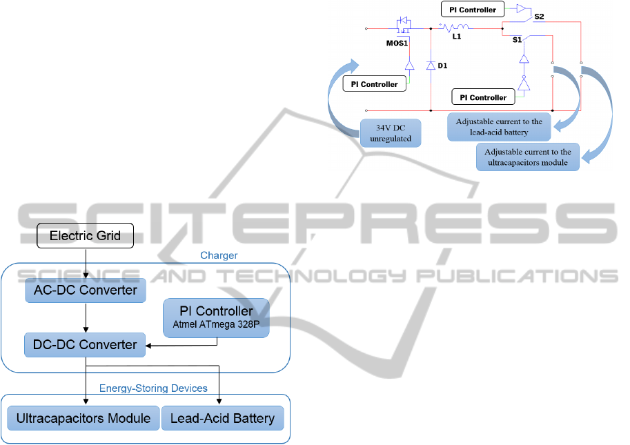
2.1 The Charger
Figure 1 shows the block diagram of the subsystem
that uses the charger. It is able to charge the
ultracapacitors module and the lead-acid battery, one
at a time. Firstly, when the charger is turned on (by
connecting it to the electrical grid), it injects current
on the ultracapacitors module as quickly as possible
(the maximum current value is 14A and the
maximum output power value is 80W) in order to
ensure ultra-fast charging. The ultracapacitors
charge process is considered completed when the
voltage goes up to 15.5V. Secondly, when the
ultracapacitors module is charged, the charger
injects 1.2A on the lead-acid battery while the
voltage does not go up to 13.8V. Thirdly, when the
battery voltage achieves 13.8V, the charger keeps
that voltage level constant until the current goes
down to 50mA. Finally, when 50mA are achieved,
the battery charging process is considered done.
The charger is fed by a 100VA, 50Hz, 230V to
24V single phase toroidal transformer. This
transformer was chosen because the maximum
output power of the charger is 80W and, in the
majority of European countries, the characteristics of
single-phase standard electric plugs are 230V AC,
50Hz and 16A (which means 3.45kVA). The
transformer is followed by a full-bridge rectifier,
which is constituted by 4 schottky diodes MBR1660,
and a 10mF capacitive filter. This set of components
is responsible for converting the alternating voltage
ICINCO2015-12thInternationalConferenceonInformaticsinControl,AutomationandRobotics
156
(230V AC) in approximately 34V DC unregulated.
Based on these characteristics, by demanding the
maximum power, the expected output voltage ripple
is around 15V
PP
. Due to the high transformer
impedance (when compared to the electrical grid
impedance), it was not necessary to develop a circuit
to avoid the high values of the start-up current.
A step-down DC-DC converter, working as a
pulse width modulation current-controlled voltage
source, is the power electronics converter used to
convert the input unregulated voltage (34V DC) to
an adjustable output current. The step-down DC-DC
converter switches at 1kHz. The control system is a
regular PI (proportional + integral) controller with a
sampling frequency of 4kHz, a proportional gain
(Kp) of 40 and an integral gain (Ki) of 100. Figure 2
shows the step-down model developed with PSIM
simulation software.
Figure 1: Block diagram of the charger.
In the converter shown in Figure 2, the PI controller
manages the duty-cycle applied to the MOSFET
MOS1. When the value of the output current is
lower than the desirable, the duty-cycle of the PWM
signal is increased. When the value of the output
current is higher than the desirable, the duty-cycle of
the PWM signal is decreased. The PI controller also
manages the state of the switches S1 and S2. When
it is necessary to charge the ultracapacitors module,
S1 is opened and S2 is closed. On the other hand,
when it is necessary to charge the lead-acid battery,
S1 is closed and S2 is opened. Figure 2 also shows
that the two switches (S1 and S2) are in series with
the coil L1. Because of that, the PI controller can
only change the state of the switches when the
current in the coil L1 is null. If this procedure was
not followed, it would appear an overvoltage spike
in the switch that opened. The diode D1 is the
schottky MBR1660, which is used to ensure the path
to the current when the MOSFET MOS1 (P80PF55)
is turned off. The current rating of the switches S1
and S2 is 16A. The coil L1 is used to smooth the
output current and it has 23.12mH, 428m at 1kHz.
Figure 2: PSIM model of the step-down of the charger.
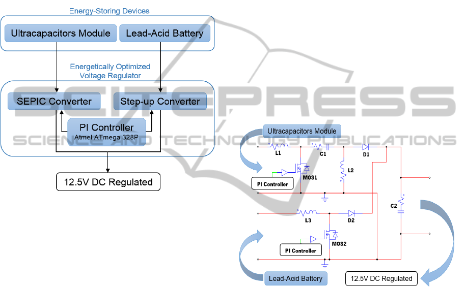
2.2 The Energetically Optimized
Voltage Regulator
Figure 3 shows the block diagram of the subsystem
that uses the energetically optimized voltage
regulator. Its main goal is to manage the available
energy on the energy-storing devices, ensuring
12.5V on its output. It is considered energetically
optimized because, firstly, it uses the energy
available on the ultracapacitors module to ensure
12.5V on its output and, secondly, when there is not
enough energy on the ultracapacitors module, it uses
the energy available on both energy-storing devices
to ensure 12.5V. This architecture has the following
advantages:
Increasing the Battery Lifespan. The fact of
using, in first place, the energy stored on the
ultracapacitors module leads to a lower battery
usage;
Reducing the Frequency of the Battery
Replacement. The increased battery lifespan
leads to a reduction of the number of times that
the battery needs to be replaced in a specific time
period. In a long term, this fact may mean the
reduce of the cost of the system in which the
battery is installed;
Due to the Use of Two Energy-storing
Devices, the Ultracapacitors Module can be
Fully Charged and Fully Discharged. So, there
is a better use of the ultracapacitors module
storage capacity.
To do the development, it was defined that the
mobile robot platform could demand up to 6A at
12V. Because of that, the energetically optimized
voltage regulator was designed to ensure a
maximum current value of 6A on its output. The
ANewEnergeticallyOptimizedPowerSupplySystemforaMobileRobotPlatform,usingUltracapacitorsandBatteriesto
EnsureBothUltra-fastChargingandAutonomy
157
reason why it was chosen 12.5V on its output
instead of 12V is related to the voltage regulator
architecture. The step-up converter does not have the
ability to block the energy flow from its input to its
output when the output voltage is lower than the
input voltage. When the battery is fully charged, its
voltage may go up to 12.5V. Therefore, using this
architecture, the way to block the energy flow (when
it is desirable) is ensuring that the output voltage is
always equal or greater than the input voltage.
Figure 3: Block diagram of the subsystem that uses the
energetically optimized voltage regulator.
The energetically optimized voltage regulator
model, developed with PSIM simulation software, is
shown in Figure 4. It is based on the SEPIC (Single-
Ended Primary-Inductor Converter) and step-up
converters. The outputs of the two converters are in
parallel and, because of that, the ground is the same
for both. The coils L1 and L2 have 42,7H and
95m at 1kHz. The coil L3 has 244H and 102m
at 1kHz. The MOSFETs MOS1 and MOS2 are the
P60NF06. The diodes D1 and D2 are the schottky
MBR1660. The capacitor C1 has 10F and the
capacitor C2 has 1mF.
When there is available energy on the
ultracapacitors module, the MOSFET MOS1 is
switched by a PI controller in order to keep the
output voltage regulated on 12.5V. In this case, the
energy only comes from the ultracapacitors module
and the MOSFET MOS2 is turned off. When the
energy on the ultracapacitors module is not enough
to keep the output voltage regulated at 12.5V, the
MOSFET MOS1 switches with 85% of duty-cycle
and the MOSFET MOS2 switches with an adjustable
duty-cycle. In this case, the energy comes from both
energy-storing devices to the output.
The computation of the PWM signal applied to
the MOSFETs MOS1 and MOS2 is based on a PI
controller with an extended output. The MOSFET
MOS1 handles a maximum duty-cycle of 85% and
the MOSFET MOS2 handles a duty-cycle value that
is given by the difference between the computed
value and 85%. For example, if the computed output
of the PI controller is 135, the duty-cycle of
MOSFET MOS1 will be 85% and the duty-cycle of
MOS2 will be 50%. The maximum duty-cycle on
each MOSFET is 85%. Therefore, the saturation
value of the PI controller is 170. The input of the PI
controller is the voltage on the output of the voltage
regulator. When its value is lower than the desirable,
the duty-cycle is increased. When its value is higher
than the desirable, the duty-cycle is decreased.
The PI controller has a proportional gain of 15
and an integral gain of 250. The sampling frequency
is about 4kHz and the switching frequency (applied
to the MOSFETs) is about 9.8kHz.
Figure 4: PSIM model of the energetically optimized
voltage regulator.
2.3 The Output Voltage Regulator
Figure 5 shows the block diagram of the subsystem
that uses the output voltage regulator. Its main
function is to supply a regulated voltage to the four
brushed DC motors of the mobile robot platform
from the 12.5V DC regulated (imposed by the
energetically optimized voltage regulator).
The output voltage regulator is based on four
independent full H-bridges. The input of each full H-
bridge is the 12.5V DC regulated and each one is
used to supply each brushed DC Motor of the mobile
robot platform. It is used a PWM signal to control
the state of each MOSFET of each bridge. The
rotation direction, the angular velocity and the
torque of each brushed DC motor are managed by a
ICINCO2015-12thInternationalConferenceonInformaticsinControl,AutomationandRobotics
158
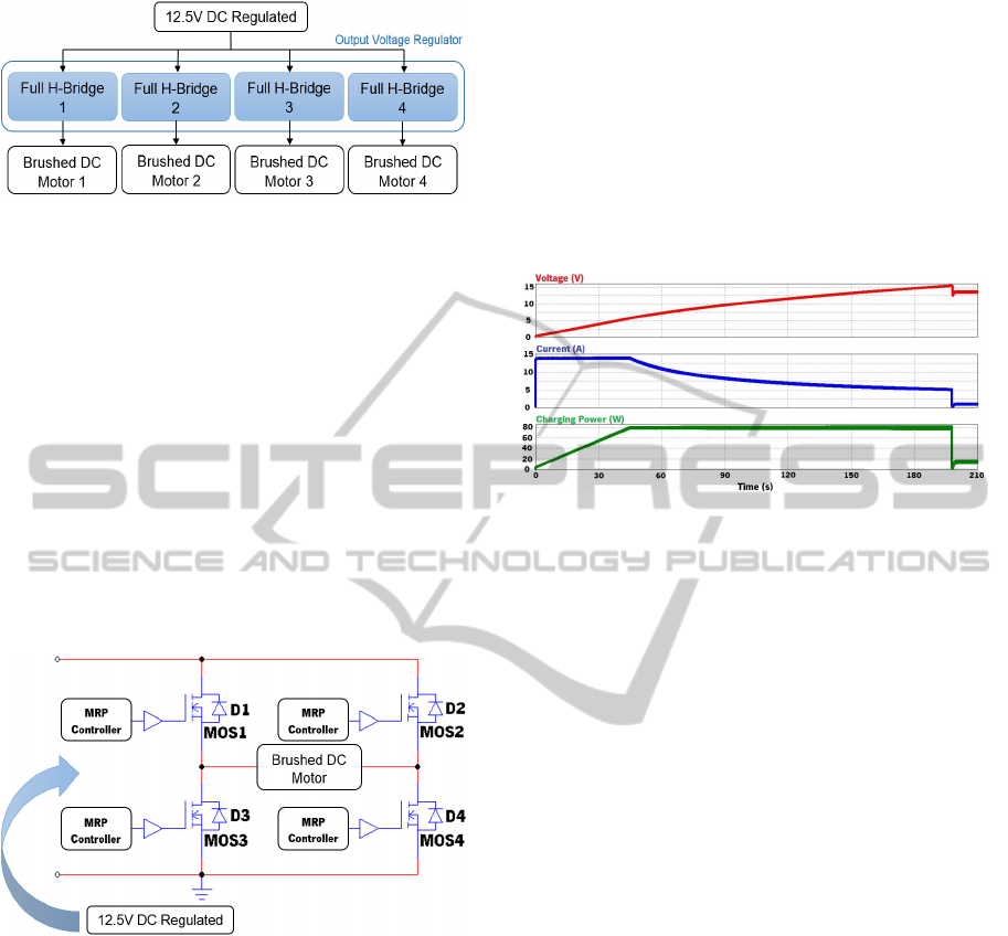
Figure 5: Block diagram of the output voltage regulator.
MRP (Mobile Robot Platform) controller. This
controller computes, for each instant, the average
voltage that should be supplied to each motor. Based
on this calculation, it is done a conversion from the
average voltage to the duty-cycle of the PWM
signal. It is used bipolar modulation, which means
that MOSFETs work in pairs – when the duty-cycle
is 100%, the average output voltage is 12.5V and
when the duty-cycle is 0%, the average output
voltage is -12.5V.
Figure 6 presents the topology used to supply
each motor. Each motor has a rated voltage of 12V
and a maximum current of 1.5A. Because of that, it
was used two L298 integrated circuits to implement
the four full H-bridges.
Figure 6: PSIM model of the output voltage regulator.
3 SIMULATION RESULTS
It was used the PSIM simulation software to validate
all the developed blocks of the power supply system.
Using this software it was possible to analyse the
expected system performance and to prevent design
mistakes before any circuit implementation, as well
as making adjustments to the gains of the PI
controllers to achieve a better overall system
performance. The most important simulations results
are presented in this section.
3.1 The Charger
The charger was simulated when it is feeding the
ultracapacitors module. A maximum output power
of 80W, a maximum output current of 14A and a
final voltage of 15.5V were considered. Figure 7
shows that the ultracapacitors module charging
process is performed successfully. It is also shown
that, when the ultracapacitors module is charged, the
system begins to charge the lead-acid battery.
Figure 7: PSIM simulation results of the charger when it is
charging the ultracapacitors module up to 15.5V.
3.2 The Energetically Optimized
Voltage Regulator
The energetically optimized voltage regulator was
simulated supplying a 12.5V, 1A load. It was
considered that the ultracapacitors module and the
battery were fully charged. In Figure 8 it is noticed
that the circuit draws more current from the
ultracapacitors module as its voltage drops, in order
to keep constant the output power. Furthermore, it is
shown that the energetically optimized voltage
regulator is able to take energy from the battery
when the voltage on the ultracapacitors module
drops too much and it is able to take almost all the
energy available on the ultracapacitors module.
3.3 The Output Voltage Regulator
The output voltage regulator was simulated
considering an input voltage of 12.5V (it is the
output of the energetically optimized voltage
regulator), a duty-cycle of 75% and an inductive
load of 6 and 500H. This simulation is important
to check the voltage and current behaviour when the
output voltage regulator is supplying a DC brushed
motor (it is an inductive load with electromotive
force). In Figure 9 it is visible that the output voltage
is a square ware, with a maximum of 12.5V and a
minimum of -12.5V, where the average output
voltage depends of the duty-cycle. In spite of the
usage of an output square wave (it is constantly
ANewEnergeticallyOptimizedPowerSupplySystemforaMobileRobotPlatform,usingUltracapacitorsandBatteriesto
EnsureBothUltra-fastChargingandAutonomy
159
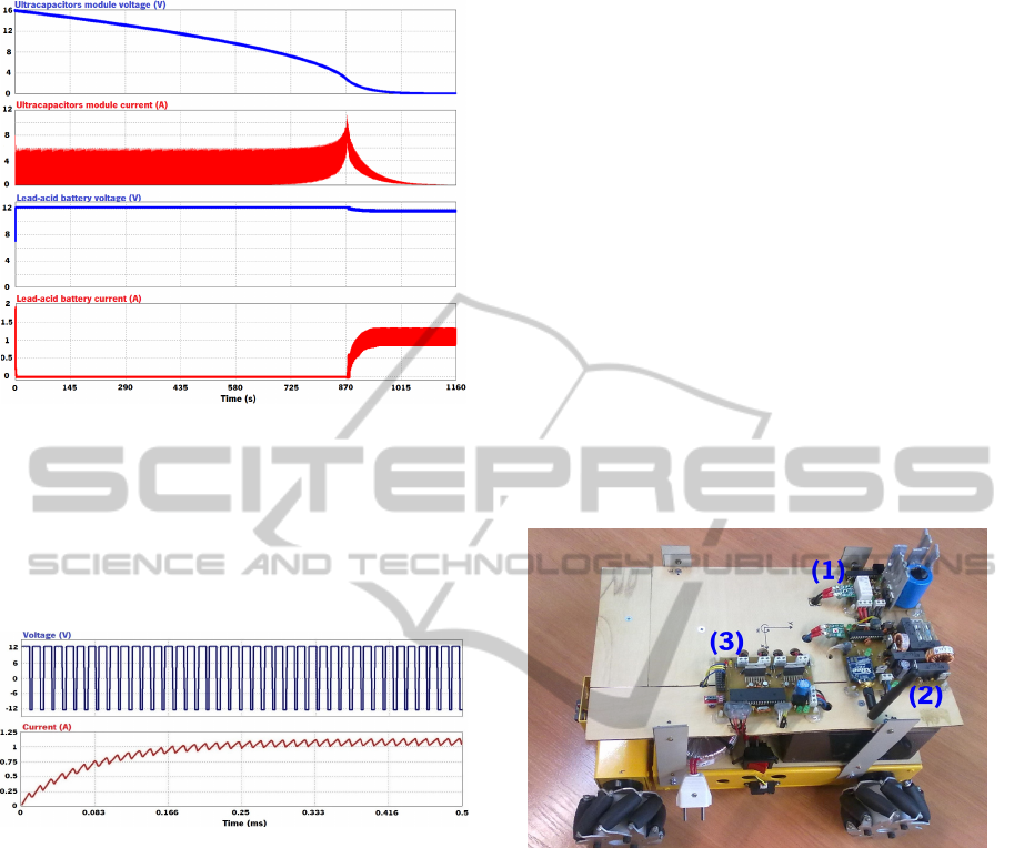
Figure 8: PSIM simulation results of the energetically
optimized voltage regulator when it is providing 12.5V,
1A on its output.
changing), there are no problems to DC brushed
motors because current is filtered by its inductance
and switching intervals are much shorter than the
mechanical time constants involved.
Figure 9: PSIM simulation results of load voltage and
current when the output voltage regulator has a duty-cycle
of 75% and an input voltage of 12.5V.
4 SYSTEM IMPLEMENTATION
Section 4 presents a detailed description of the real
system implementation. It was done after having
simulated and validated all the system architecture
by using the PSIM simulation software.
4.1 Hardware
The charger is able to charge both energy storing
devices. It charges the ultracapacitors module in first
place and then it charges the lead-acid battery. This
strategy was followed so as to ensure ultra-fast
charging (reducing at minimum the charging time).
The charger hardware was fully mounted onboard
the mobile robot platform to ensure that whenever it
is necessary to charge, no external additional
hardware is needed – Unlike a previous work by
Arantes et al., (2014), the charger does not need of a
dedicated charging station. The hardware
implementation was made by developing a printed
circuit board (PCB) using the CadSoft Eagle 6.4.
The energetically optimized voltage regulator is
capable of providing 12.5V on its output from the
energy available on both energy storing devices. Its
PCB implementation can be seen in Figure 10. That
Figure also shows the final implementation of the
whole power supply system: the charger, the
energetically optimized voltage regulator and the
output voltage regulator. The output voltage
regulator is able to provide the suitable average
voltage for each brushed DC motor ensuring that the
mobile robot platform moves to where is required.
That voltage is computed by the MRP controller,
which is based on the Atmel ATmega 1284P
microcontroller.
Figure 10: Final version of the mobile robot platform. It is
visible the whole power supply system: the charger PCB
(1), the energetically optimized voltage regulator PCB (2)
and the output voltage regulator PCB (3).
4.2 Software
The charger is capable of charging both energy
storing devices. For each time instant, the operation
mode of the charger is dependent of the energy
storing device that is being charged. The output
current and voltage of the charger are managed by
the algorithm that was described in Section 2.
The energetically optimized voltage regulator
uses a non-conventional digital PI controller, which
was implemented on another Atmel ATMega 328P
microcontroller. Its main particularity is the fact that
it has an extend output to deal with both SEPIC and
step-up converts. According to the algorithm, for a
computed duty-cycle equal or lower than 85%, it is
switched only the SEPIC converter. For higher duty-
ICINCO2015-12thInternationalConferenceonInformaticsinControl,AutomationandRobotics
160

cycle values, both converters are switched having in
account that, for each converter, the duty-cycle value
can never be higher than 85%. If that precaution was
not taken, due to the nature of the circuit, the power
converters could be destroyed by a short circuit.
The output voltage regulator takes the 12.5V
from the energetically optimized voltage regulator
and provides the suitable average voltage for each
brushed DC motor of the mobile robot platform. It
was implemented a digital PID controller to ensure
that each wheel of the mobile robot platform has a
measured velocity that closely follows a reference
velocity specified by the MRP controller, whose
main function is to define the trajectories of the
mobile robot platform. The algorithm of the output
voltage regulator was implemented on an Atmel
ATmega 1284P microcontroller.
All the Atmel ATmega microcontrollers used on
the power supply system were programmed using
the Atmel Studio 6.1 software.
5 EXPERIMENTAL RESULTS
Some experimental tests were made to ensure the
correct operation of each component of the system
and to further validate the proposed topology.
5.1 The Charger
The charger module was tested by charging the two
energy-storing devices. By considering only
theoretical calculations, the expected charging time
for the ultracapacitors module was, approximately, 3
minutes and 20 seconds. Because the charging
current is limited to a maximum of 14A, the
maximum charging power (80W) was only achieved
when the voltage in the ultracapacitors module
reached 5.7V. The practical results showed that the
real charging time is 3 minutes and 42 seconds. The
cause of the time gap between theoretical and
practical results is the fact that theoretical
calculations did not consider all the circuit losses
and parasitic effects. Some of them are very hard
and require very expensive equipment to be
assessed. The ultracapacitors module charging was
considered done when its voltage reached 15.5V.
After that, the lead-acid battery charging proceeded.
The measured charging time for the battery was
approximately 8 hours and 30 minutes.
5.2 The Energetically Optimized
Voltage Regulator
The main function of this voltage regulator is to
ensure 12.5V at its output using the energy available
on both the ultracapacitors module and the battery
by extracting energy from both of them. For an
ultracapacitors module voltage equal or higher than
2.48V, the voltage regulator only uses the energy
available on the ultracapacitors module. For an
ultracapacitors module voltage lower than 2.48V,
the system uses the energy available on both energy
storing devices.
It was also found that the energetically optimized
voltage regulator is able to extract almost all the
energy available on the ultracapacitors module,
taking its voltage almost to 0V.
5.3 The Output Voltage Regulator
The output voltage regulator is the last stage of the
power supply system of mobile robot platform.
Considering both energy storing devices fully
charged and running some experimental tests, it was
found that, by placing the mobile platform on a flat
surface at maximum speed (approximately 60 cm/s),
the average autonomy was 23 minutes and 13
seconds using only the available energy on the
ultracapacitors module. Using all the available
energy on both sources it was achieved an autonomy
of approximately 9 hours and 40 minutes.
6 CONCLUSIONS AND FUTURE
DEVELOPMENTS
An electrical power supply system for a mobile
robot platform has been developed. The system uses
ultracapacitors and batteries as energy-storing
devices. This paper described a major improvement
of a previous work done by Arantes et al., (2014), as
the new system is much lighter and more compact,
which allowed all of its components to be mounted
onboard the mobile robot platform. The system is
composed of three modules: 1) a charger and the
energy-storing devices; 2) an energetically
optimized voltage regulator; 3) an output voltage
regulator.
With regard to the charger, the charging time
measured for the ultracapacitors module was,
approximately, 3 minutes and 42 seconds (starting
with a fully-discharged module). Because the
charging current is limited to a maximum of 14A,
ANewEnergeticallyOptimizedPowerSupplySystemforaMobileRobotPlatform,usingUltracapacitorsandBatteriesto
EnsureBothUltra-fastChargingandAutonomy
161

the maximum charging power (80W) was only
achieved when the ultracapacitors module voltage
reached 5.7V. The ultracapacitors module charging
was completed when its voltage reached 15.5V.
After that, the lead-acid battery charging proceeded.
A small disturbance is visible in the voltage and
current waveforms at the output of the energetically
optimized voltage regulator, considering a power of
12.5W. This is due to the starting of the step-up
converter. Until then, only the ultracapacitors
module was providing power to the load. Observing
the voltage and current waveforms in the
ultracapacitors module, it is possible to conclude
that the average current value tends to increase due
to the decreasing in the average voltage value, as
expected, because only then is it possible to maintain
a constant output power.
Regarding the practical implementation of the
two previous systems, printed circuit boards were
implemented using the Eagle Cadsoft 6.4 and digital
PI controllers were developed with Atmel Studio 6.1
and microcontrollers Atmel ATmega 328P.
The output voltage regulator is the last stage of
the power supply system. It is responsible for
supplying the suitable average voltage to the motors
of the mobile robot platform. Autonomy tests were
made and it was found that, if the mobile robot
platform is placed on a flat and horizontal surface at
maximum speed (about 60 cm/s), the average
autonomy is about 23 minutes and 13 seconds using
only the available energy in ultracapacitors module.
From that moment, which corresponded to an
ultracapacitors module voltage of 2.48V, the system
started to use the energy available in both sources
and achieved an autonomy of, approximately, 9
hours and 40 minutes. It was verified that the system
was able to extract almost all of the energy stored in
the ultracapacitors module, taking its voltage almost
to 0V. Regarding the practical implementation of
this last system, a printed circuit board was also
developed through the Eagle Cadsoft 6.4, and a
digital PID controller was implemented using the
Atmel software Studio 6.1 and the microcontroller
Atmel ATmega 1284P.
As a future development, it is suggested to
modify the circuits and the control systems in order
to allow energy interchange between the
ultracapacitors module and the batteries. This will
improve energy efficiency in the event that only a
fraction of the energy stored in the ultracapacitors
module is used.
ACKNOWLEDGEMENTS
This work has been supported by FCT – Fundação
para a Ciência e Tecnologia in the scope of the
project: PEst-UID/CEC/00319/2013.
REFERENCES
Arantes, C., Sepúlveda, J., Esteves, J., Costa, H., Soares,
F., Using Ultracapacitors as Energy-storing Devices
on a Mobile Robot Platform Power System for Ultra-
fast Charging; ICINCO 2014, 11th International
Conference on Informatics in Control, Automation and
Robotics, 2014, Page(s): 156 – 164, ISBN 978-989-
758-040-6. DOI: 10.5220/0005061801560164.
Awerbuch, J. J., Sullivan, C. R., Filter-based Power
Splitting in Ultracapacitor-Battery Hybrids for
Vehicular Applications; COMPEL 2010, Control and
Modeling for Power Electronics, 2010, Pages(s): 1 –
8. DOI: 10.1109/COMPEL.2010.5562429.
Bernholc, J., Ranjan, V., Zheng, X. H., Jiang, J., Lu, W.,
Abtew, T. A., Boguslawski, P., Nardelli, M. B.,
Meunier, V., Properties of High-Performance
Capacitor Materials and Nanoscale Electronic
Devices; HPCMP-UGC 2010, High Performance
Computing Modernization Program Users Group
Conference, 2010, Page(s): 195 – 200. DOI:
10.1109/HPCMP-UGC.2010.76.
Haifeng, Dai and Xueyu, Chang; A Study on Lead Acid
Battery and Ultra-capacitor Hybrid Energy Storage
System for Hybrid City Bus; ICOIP 2010,
International Conference on Optoelectronics and
Image Processing, 2010, Page(s): 154 – 159. DOI:
10.1109/ICOIP.2010.321.
Kularatna, N., Patel, A., Supercapacitors for Energy
Mangement in Autonomous Sensor Nodes; WAC,
World Automation Congress, 2014, Page(s): 604 –
609. DOI: 10.1109/WAC.2014.6936064.
Monteiro, J., Garrido, N., Fonseca, R., Efficient
Supercapacitor Energy Usage in Mobile Phones; ICCE
2011, 2011 International Conference on Consumer
Electronics – Berlin, 2011, Pages(s): 318 – 321. DOI:
10.1109/ICCE-Berlin.2011.6031796.
Muffoletto, D., Mandris, C., Olabisi, S., Burke, K.,
Zirnheld, J., Moore, H., Singh, H., Design and
Analysis of a Smart Power Management System for
Ultracapacitor-Powered Robotic Platform; IPMHVC,
Power Modulator and High Voltage Conference,
2010, Page(s): 643 – 646. DOI:
10.1109/IPMHVC.2010.5958441.
Musat, A. M., Carp, M., Borza, P., Musat, R., Sojref, D.,
Hybrid Storage Systems and Dynamic Adapting
Topologies for Vehiche Applications; OPTIM 2012,
2012 13th International Conference on Optimization
of Electrical and Electronic Equipment, 2012, Page(s):
1842 – 1566. DOI: 10.1109/OPTIM.2012.6231910.
Niemoeller, B. A. and Krein, P. T., Battery-Ultracapacitor
ICINCO2015-12thInternationalConferenceonInformaticsinControl,AutomationandRobotics
162

Active Parallel Interface with Indirect Control of
Battery Current; PECI 2010, Power and Energy
Conference at Illinois, 2010, Pages(s): 12 – 19. DOI:
10.1109/PECI.2010.5437163.
Petchjatuporn, P., Wicheanchote, P., Khaehintung, N.,
Kiranon, W., Sunat, K., Chiewchanwattana, S.,
Intelligent ultra-fast charger for Ni-Cd batteries;
ISCAS 2005, IEEE International Symposium on
Circuits and Systems, 2005, Page(s): 5162 – 5165 Vol.
5. DOI: 10.1109/ISCAS.2005.1465797.
Qin, G., Zhu, H., Hybrid Power Supply of Rescue Robot
Based on Supercapacitors; ICMACE 2011, 2th
International Conference on Mechanic Automation
and Control Engineering, 2011, Page(s): 1350 – 1353.
DOI: 10.1109/MACE.2011.5987194.
Schneuwly, A., Gallay, R., Properties and Applications of
Supercapacitors from the State-of-Art to Future
Trends; Proceeding PCIM 2000, 2000.
Siguang, Li, Chengning, Zhang, Shaobo, Xie, Research
on Fast Charge Method for Lead-Acid Electric
Vehicle Batteries; ISA 2009, International Workshop
on Intelligent Systems and Applications, 2009,
Page(s): 1 – 5. DOI: 10.1109/IWISA.2009.5073068.
ANewEnergeticallyOptimizedPowerSupplySystemforaMobileRobotPlatform,usingUltracapacitorsandBatteriesto
EnsureBothUltra-fastChargingandAutonomy
163
