
Distributed Discrete Event Simulation Architecture with Connectors
˙
Ismet
¨
Ozg
¨
ur C¸ olpankan
1,2
, Ahmet Kara
2
and Halit O
˜
guzt
¨
uz
¨
un
1
1
Department of Computer Engineering, Middle East Technical University, Ankara, Turkey
2
T
¨
UB
˙
ITAK B
˙
ILGEM
˙
ILTAREN, Ankara, Turkey
Keywords:
DEVS, SiMA, Distributed DEVS, Connectors.
Abstract:
Distributed Discrete Event System Specification (DEVS) environments are developed with various computing,
networking and implementation language options. We propose a distributed approach to the Simulation Mod-
eling Architecture (SiMA), a DEVS-based modeling and simulation framework, with software connectors.
We employ Windows Communication Foundation (WCF) as the middleware technology. A connector is a first
class entity which performs interaction among components, thus, plays an important role in a component-based
architecture. We claim that using a connector instead of modifying an already developed model increases the
model reusability. We also compare this approach with the existing distributed DEVS approaches in terms
of base formalism, network layer technology, model partitioning, remote node synchronization scheme and
message exchange pattern.
1 INTRODUCTION
Complex model hierarchy, high level of detail in mod-
els and large simulations cause the processor and
memory of a computer to become insufficient to run
a simulation in a reasonable time. Therefore, the
need to use diverse resources dispersed over a net-
work for a scalable performance leads to develop-
ment of parallel and distributed simulation systems.
Distributed DEVS idea was launched in 1985 by
Zeigler (Zeigler, 1985) and until today several dis-
tributed DEVS applications have been developed, in-
cluding: DEVS/CLUSTER (Kim and Kang, 2004),
DEVS/RMI (Zhang et al., 2005), DEVS/P2P (Cheon
et al., 2004), and DEVS/SOA (Mittal et al., 2009).
In this paper, we propose a distributed approach
to enable Simulation Modeling Architecture (SiMA)
to execute in a distributed environment. SiMA is a
DEVS-based modeling and simulation framework de-
veloped in T
¨
UB
˙
ITAK B
˙
ILGEM
˙
ILTAREN. It imple-
ments the SiMA-DEVS formalism which is an ex-
tended version of Parallel DEVS formalism. Our ap-
proach is using Windows Communication Foundation
(WCF) (Cheng, 2010) as an underlying middleware
technology. WCF offers a set of APIs in the .NET
framework (Millas, 2013) for establishing service-
oriented applications (Cheng, 2010). Core simulation
engine of SiMA was developed in .NET framework,
hence WCF might be attuned to SiMA easily. Further-
more, in a WCF-to-WCF application the fastest mes-
sage encoding formatting and transfer protocol meth-
ods can be utilized considering the other facilities that
WCF offers.
Our approach is also integrating the concept
of software connectors for adaptation of distributed
nodes and models. The increase in modeling com-
plexity leads to utilization of already developed
reusable models. Furthermore, model reuse saves de-
velopers development effort and time, and more im-
portantly regression tests to verify and validate the
modified model. However, it is not always feasi-
ble to use a legacy model in a new simulation sce-
nario in terms of detail of computation and data
types for communication among models. Connec-
tors engage at this point by providing interactions
among components by transferring control or data,
and playing the gluing role in component-based archi-
tectures. Besides, DEVS formalism is highly appro-
priate for a component-based framework design when
each model is considered as a component. Therefore,
in our implementation we have adopted connectors as
introduced by Kara (Kara et al., 2014) for Distributed
DEVS environments to perform data conversions and
data marshalling/unmarshalling.
Novelty of our approach is the explicit use of con-
nectors for adaptation of distributed nodes and mod-
els via favorable WCF features in a distributed DEVS
environment.
130
Çolpankan I., Kara A. and Oguztüzün H..
Distributed Discrete Event Simulation Architecture with Connectors.
DOI: 10.5220/0005531801300137
In Proceedings of the 5th International Conference on Simulation and Modeling Methodologies, Technologies and Applications (SIMULTECH-2015),
pages 130-137
ISBN: 978-989-758-120-5
Copyright
c
2015 SCITEPRESS (Science and Technology Publications, Lda.)

The rest of the paper is organized as follows: Sec-
tion 2 provides an overview of the background of our
research, Section 3 provides distributed DEVS ap-
proaches related to our research, Section 4 explains
our approach in detail, Section 5 presents a case study
using our implementation and our discussions about
the importance of our approach, and finally Section 6
includes our resultant comments.
2 BACKGROUND
2.1 SiMA
SiMA (Kara et al., 2009) is a modeling and simula-
tion framework that is built on DEVS formalism (Zei-
gler, 1976). For complex model construction it uses a
formalism which extends the Parallel DEVS formal-
ism (Chow and Zeigler, 1994). SiMA has two ex-
tensions to the parallel DEVS formalism; strongly-
typed inter model connection environment and direct
feed through transition function. In port definitions
of models there are constraints that makes port types
type-safe. Moreover, the new transition function pro-
vides that in the same simulation time a model can re-
ceive data, make computation on it, and send the mod-
ified data without any state change. It has its own port
type, direct feed through port, in order to process in-
coming events and send them in the same simulation
time. To avoid deadlocks, an application independent
loop-breaking logic is defined in this port type.
2.2 Connectors
Connectors are the architectural building blocks that
manage the interactions among components (Amirat
et al., 2009). Some examples of interactions are pro-
cedure calls, method invocations, data flow, commu-
nication protocol, and pipelines. Mehta and his col-
leagues (Mehta et al., 2000) proposes eight connec-
tor types; procedure call, event, data access, link-
age, stream, arbitrator, adaptor, and distributor. In
our study, we take the classification of Mehta into ac-
count.
3 RELATED WORK
This section summarizes of some Distributed DEVS
approaches.
DEVS/P2P (Cheon et al., 2004) is a distributed
DEVS implementation that proposes a peer-to-peer
(P2P) simulation protocol to operate a DEVS simula-
tion on a distributed and parallel computing environ-
ment. The proposed protocol uses advantage of P2P
infrastructure, in which inter-connected peers share
resources with each other without using any central-
ized administrative system, to gain optimal perfor-
mance compared to existing protocols. As middle-
ware it uses JXTA (Wilson, 2002) technology which
is a P2P network system implementation.
DEVS/GRID (Seo et al., 2004) uses Grid comput-
ing infrastructure for DEVS modeling and simulation
activities. DEVS/GRID proposes new functionalities
to the existing DEVS M&S frameworks as mentioned
by Seo (Seo et al., 2004): ”cost-based hierarchical
model partitioning, dynamic coupling restructuring,
automatic model deployment, remote simulator acti-
vation, self-communication setup, M&S name and di-
rectory service, etc.” As middleware, Globus Toolkit
which is widely used in grid computing is used.
DEVS/CLUSTER (Kim and Kang, 2004) trans-
forms hierarchical DEVS model structure into a non-
hierarchical one to ease the synchronization of re-
mote models. DEVS/CLUSTER utilizes CORBA as
a communication system which is designed to per-
form collaboration between heterogeneous platforms,
different programming languages and operating sys-
tems.
DEVS/RMI (Zhang et al., 2005) focuses mostly
on the reconfiguration of the simulation structure dy-
namically in runtime unlike other approaches. Its un-
derlying communication technology is Java RMI.
DEVS/SOA (Mittal et al., 2009) provides a so-
lution to cross-platform distributed M&S in a client-
server architecture using SOA. It uses Java for the im-
plementation. Messages between remote nodes are
serialized with SOAP.
DEVS/PyRo (Syriani et al., 2011) is designed to
make quantitative analysis of reliability and perfor-
mance of different simulator designs with detection
of failures in computational and network resources. It
is implemented in Python. PyRO which is an RMI-
based python implementation is used in middleware
layer.
4 DISTRIBUTED SiMA
Distributed SiMA is a framework that enables SiMA
to execute in a distributed environment. It also aims to
increase model reusability by bringing software con-
nector notion to distributed DEVS environment. Con-
nectors in Distributed SiMA assist inter node com-
munication and adaptation of models in terms of
port data types. Distinctively from other distributed
DistributedDiscreteEventSimulationArchitecturewithConnectors
131
Model 1 Model 2
Type1
Type2
(a) Located in the same node
Model 1
Marshaller 1
Marshaller 2 Unmarshaller 2
Unmarshaller 1
Network
Model 2
Type1
Type1
Type2
Type2
Serialized object
Serialized object
Marshaller/Unmarshaller Connector
Marshaller/Unmarshaller Connector
(b) Located in remote nodes
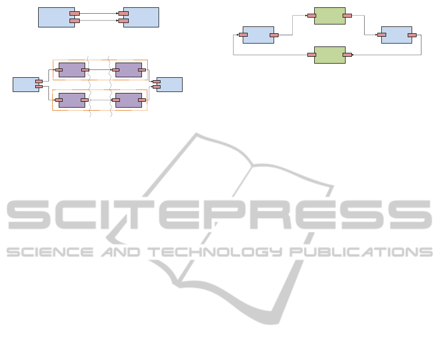
Figure 1: Marshaller/Unmarshaller Connectors
DEVS approaches Windows Communication Foun-
dation is adopted as an underlying middleware tech-
nology. Like SiMA core engine Distributed SiMA
has been implemented in .NET C#. Besides, WCF
is convenient to adapt two .NET products with each
other in terms of performance. In Distributed SiMA
many WCF features are benefited such as service
oriented development environment for simplicity, re-
quest/reply message exchange pattern for synchro-
nization, binary encoding over TCP transportation for
performance and customized service behavior for ob-
ject serialization.
4.1 Connectors in Distributed SiMA
Distributed SiMA uses connectors which play im-
portant roles in simulation execution. Connectors in
Distributed SiMA are the specialized atomic models.
There are two kinds of connectors in terms of the
tasks they carry out: marshaller/unmarshaller connec-
tor and data conversion connector.
4.1.1 Marshaller/Unmarshaller Connector
It consists of two built-in atomic models used in com-
munication among remote models. If there is a port
coupling between two models (coupled or atomic)
located at different nodes, a marshaller/unmarshaller
connector is placed between the models in order to
serialize and deserialize the port data. The marshaller
part of the connector is placed in the source node, and
the source model’s output port is connected to its in-
put port. Similarly the unmarshaller part of the con-
nector is placed in the target node, and its output port
is connected to the target model’s input port. A port
coupling of two models in Figure 1a can be trans-
formed for a distributed environment as in Figure 1b
with marshaller/unmarshaller connectors.
Conceptually, there is a one connector that per-
forms marshalling and unmarshalling, in addition to
Model 1
Type1 to Type2
Data Conversion
Connector
Model 2
Type2 to Type1
Data Conversion
Connector
Type1
Type1
Type2
Type2
Figure 2: Data Conversion Connectors.
networking chores. In terms of implementation, it is
composed of two atomic DEVS models (one for mar-
shalling, the other for unmarshalling), and the under-
lying network. Marshalling/Unmarshalling connec-
tor uses direct feed through transition port. Therefore
there is no simulation time step loss between remote
models despite the connectors between them. Model
1 sends data to Marshaller 1. In the same simulation
time step Marshaller 1 serializes the data and sends it
through network to Unmarshaller 1. Unmarshaller 1
deserializes the data and sends it to the Model 2. With
the help of WCF there is no need for an extra synchro-
nization while sending port data through network.
4.1.2 Data Conversion Connectors
Model continuity is a profitable characteristic when
huge simulation projects are considered. Already
implemented atomic models can be used in other
projects without modifications. Modelers might not
want to break the integrity of already developed mod-
els since the verification and validation time of the
modified model may take more time than develop-
ing a new model. However, data types processed by
the legacy models might not match the data types of
the new models. Evidently, composable models may
reflect the same real world entities and facts; how-
ever, they might have non-identical data representa-
tions. These models have to communicate with each
other but port data types they are using are not the
same. Data conversion connectors (Kara et al., 2014)
accomplish this bridging task. They receive a data
packet in Type1, apply conversion to it, and send it
in Type2 like in Figure 2. They are implemented by
the model developers as atomic models. Distributed
SiMA provides a base class for the developers to de-
velop connector models that utilize DFT ports for
conversion routines.
4.1.3 Connector Roles According to Mehta
Classification
Mehta and his colleagues stated eight connector types
mentioned in Section 2.2. A connector may have
more than one type among them.
SIMULTECH2015-5thInternationalConferenceonSimulationandModelingMethodologies,Technologiesand
Applications
132
User initializes model
deployment and test
Models are deployed
Deployed models are
tested in each node
Deployment process
finishes and user is
notified
User initializes the
simulation build
process
Model instances are
created in each node and
port couplings are
established
Simulation building
process finishes and user
is notified
User initializes the
simulation run
Simulation runs in
distributed environment
User interaction
Master and Slave nodes
Not working properly
Working properly
Model Deployment
Simulation Build and Run
Simulation finishes and
user is notified
User collects the
simulation output
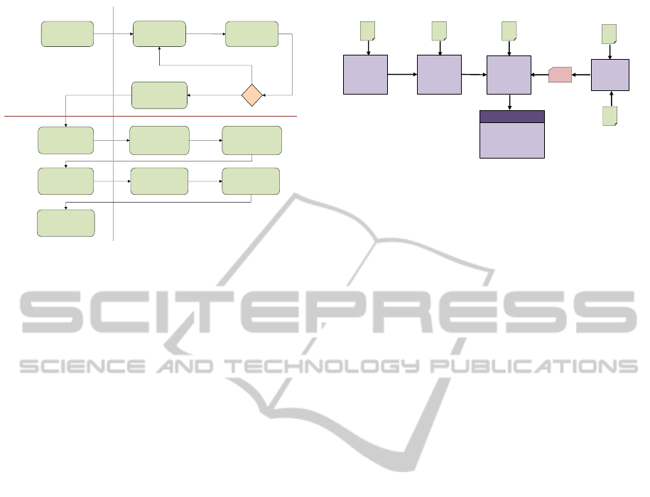
Figure 3: General System Flow Diagram.
Marshaller/Unmarshaller connectors are pro-
cedure call connectors since they make remote proce-
dure calls. They are also linkage connectors as they
are not defined as a simulation entity before simu-
lation construction, but they are inserted to simula-
tion when a remote model port data transportation is
needed. They establish the WCF communication pro-
tocol and serializes data to be sent over network, so
they are adaptor connectors.
Data conversion connectors are mostly adaptor
connectors, because they provide data conversion ser-
vice among components. They also form binding be-
tween different typed models and this makes them
linkage connectors.
4.2 Distributed SiMA Architecture
We used the existing SiMA implementation as a basis
to develop Distributed SiMA. We added new pack-
ages, extended the core classes, and modified some
classes for the distributed version. There is a Mas-
ter Node managing the whole system by deploying
models, building simulation, and executing simula-
tion. Other remote nodes joining the simulation ex-
ecution are called Slave Nodes.
Distributed SiMA could be examined in two main
phases with respect to distributed simulation execu-
tion: model deployment, and simulation build and run
as illustrated in Figure 3.
4.2.1 Model Deployment
This phase covers identifying slave nodes, establish-
ing connections, deploying and testing of models in
them. Before all of these, slave nodes must be ready
for the model deployment. For the model deploy-
ment slave nodes need starting the Model Deployment
Distributed
Scenario
Analyzer
Distributed
Scenario
Document
Data Type
Mapping Rules
XSLT
Distributed
Model
Linker
Distributed
Model
Builder
KODO
Port Type
Mapping Rules
XML
XML
KODO Data Type
Definitions
XML
Code Generation
Rules
XSLT
Port Data
Structures
Simulation Models
in Distributed
Environment
Distributed Simulator
Figure 4: Distributed SiMA Simulation Construction
Pipeline.
Server and creating a service listener for the connec-
tion. We use Windows services that operate in the
background, and are managed by the operating sys-
tem. We developed a Windows service to instantiate
the Deployment Service.
Slave nodes behave like servers after these steps
and start to listen via Deployment Service port for
the connection requests. This service is used in the
deployment phase of Distributed SiMA. User ini-
tializes the model deployment process with the dis-
tributed scenario definition document which consists
of model definition, coupling information, initializa-
tion parameters of models, and endpoint addresses of
slave nodes added to coupled or atomic model defini-
tions.
4.2.2 Simulation Build and Run
Model Deployment guarantees that all simulation
models are dispatched over the network and tested
on the corresponding slave nodes. In this phase dis-
tributed simulation will be built and run. Distributed
SiMA employs basic SiMA simulation construction
pipeline as a base and extends it to build distributed
simulation. Again master node maintains the system
building process. The distributed version of the SiMA
simulation construction pipeline is in Figure 4.
Distributed Scenario Analyzer starts the dis-
tributed simulation construction pipeline. In Dis-
tributed SiMA, Scenario Document is modified as
Distributed Scenario Document that includes the def-
inition of the partition plan. User writes Deploy-
ment Service endpoint address of a slave node in-
side the definition of the model (atomic or coupled)
he wants to work as remote. This modification on
scenario document is enough to make a basic SiMA
scenario distributed. Distributed Scenario Analyzer
takes a Distributed Scenario Document file as an in-
put and creates an intermediary data for Distributed
Model Linker. The Distributed Scenario Document
consists of model definition, model coupling informa-
tion with remote node endpoint addresses, and initial-
DistributedDiscreteEventSimulationArchitecturewithConnectors
133

ization data of the models.
Distributed Model Linker is the core compo-
nent among the others taking role in the pipeline.
It prepares the distributed simulation structure to
be built. The intermediary scenario received from
Distributed Scenario Analyzer is separated into two
files in this component. One of the files is the
distributed model link map file including the cou-
pling information, model definitions, and port con-
nection definitions using a hierarchical style. The
other file is the distributed simulation configuration
file consisting of initialization data of the atomic
models. User specifies the required data conversion
connectors; however, the document does not include
marshaller/unmarshaller connector definitions. Dis-
tributed Model Linker inserts them where they are re-
quired.
Distributed Model Builder is the constructor of
the Distributed SiMA. It manages the creation of in-
stances of model classes. It establishes one root cou-
pled model by combining the instances according to
hierarchical structure for each node. This hierarchical
structure is obtained from the distributed model link
map file produced by Distributed Model Linker. For
the models to be run in master node, it builds them
locally. And for the remote models it commands the
slave nodes to build the remote coupled models via
Remote Simulation Service. There are also remote
model proxies located in the master node for each
remote coupled model. Their task is to provide a
communication setup in order to communicate with
Remote Simulation Service. They are images of the
remote coupled models in master node. Distributed
Simulator manages the distributed simulation on mas-
ter node as if it is local. It thinks that all models are lo-
cated in one computer. Actually remote model prox-
ies create this illusion.
Figure 5 illustrates the configuration of an ex-
ample system. There is a Master Node and two
slave nodes. Slave Node 2 has two sessions to man-
age different remote models. Remote model prox-
ies in Master Node connect Remote Simulation Ser-
vices (RSSs) in slave nodes. Marshaller modules
of Marshallar/Unmarshaller Connector (MCs) con-
nect the related Unmarshaller modules of Marshal-
lar/Unmarshaller Connector (UMCs) through Port
Services (PSs).
KODO is not adjusted to distributed SiMA since
the port and initial data classes generated are used as
they are. Actually in WCF user specifies the port data
classes transported through network by tagging them
with Data Contract property. The .NET framework
detects that the class will be serialized by WCF. How-
ever, we did not develop a new distributed version
Coupled0
Coupled1
Atomic1
Atomic2 Coupled2
Atomic3 Atomic4
Atomic5
Coupled3
Atomic6 Atomic7
Atomic8
Atomic9
Remote1_1 Remote2_1 Remote2_2
MASTER
NODE
Remote1_1_Proxy
Remote2_1_Proxy
Remote2_2_Proxy
UMC1 MC2
MC1 UMC2
MC3
UMC4
UMC3 MC4
MC5
UMC6
UMC5
MC6
SLAVE
NODE 1
SLAVE
NODE 2
RSS
RSS
RSS
PS
PS
PS
PS
PS
PS
Figure 5: Distributed Simulation Structure Example
Overview.
of KODO or modify the generated classes. Because
it brings some work load and also ruins the easiness
of making an already developed SiMA scenario dis-
tributed. One would have to run the new distributed
KODO to add Data Contract property to all gener-
ated classes. We resolved this problem by changing
the Port Service data serialization behavior. In de-
fault WCF expects to serialize only Data Contracts.
With the changing service serialization behavior, all
port data classes can be serialized into the object class
which is the base class of all classes in .NET. This
feature of WCF serialization behavior can be used be-
cause of WCF-to-WCF communication. There is not
a cross-platform communication and we can use the
benefits of WCF-to-WCF communication in both data
transport optimization and serialization.
Distributed Simulator maintains the centralized
view of simulation execution as in SiMA. However,
it is distributed since there are remote model proxies
in place of the actual models. At the management
level Parallel DEVS protocol is applied. Simulation
execution is synchronized in terms of simulation time
management as a default because of its central archi-
tecture and request/reply feature in remote procedure
calls of WCF. There is no need for an extra global or
local simulation time synchronization among remote
nodes.
5 CASE STUDY
This section includes a case study to demonstrate Dis-
tributed SiMA. The scenario used in the case study
is a wireless ad hoc sensor network (Yick et al.,
2008). There are two kinds of sensor models in the
scenario: detailed sensor model and regular sensor
model. There is also a sink model gathering sen-
sor information. A logger model is used to trace
the local and distributed models’ activities. A plat-
form model is used as a target to be detected by sen-
sors and make them send detection information to the
sink model. Moreover, there are connectors; Regu-
SIMULTECH2015-5thInternationalConferenceonSimulationandModelingMethodologies,Technologiesand
Applications
134
larToDetailedSensorInfo and DetailedToRegularSen-
sorInfo connector between regular sensor models and
detailed sensor models, and DetailedToRegularPlat-
formInfo connector between platform and regular
sensor models. All scenario models and relations be-
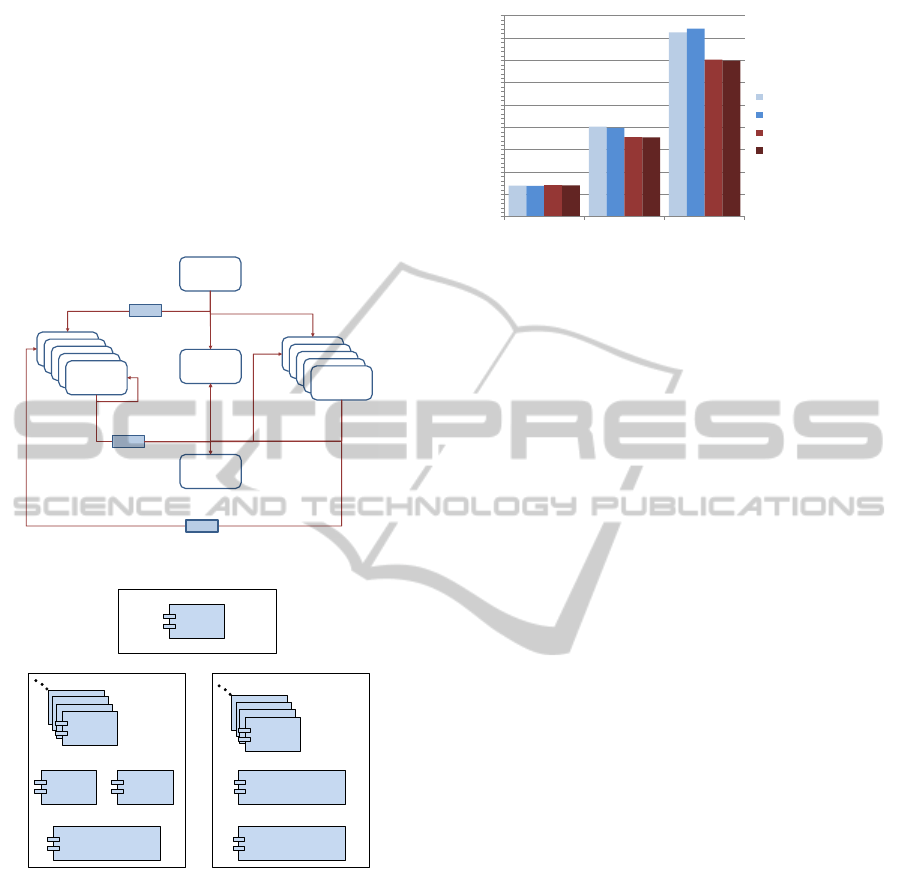
tween them are observed from Figure 6. As the aim
of this case study is not a WSN evaluation, the im-
plementation of models does not reflect the exact cal-
culations needed to be done in a real wireless ad hoc
sensor network.
Platform
Model
Logger Model
Sink Model
Regular Sensor Info
Detailed Platform Info
Sensor Model
Sensor Model
Sensor Model
Sensor Model
Regular
Sensor Model
Detailed
Sensor Model
Detailed
Sensor Model
Detailed
Sensor Model
Detailed
Sensor Model
Detailed
Sensor Model
Regular Platform Info
Detailed Sensor Info
Connector
Connector
Connector
Detailed Sensor Info
Regular Sensor Info
Figure 6: Models in the Case Study Scenario.
Detailed Sensor
Model 1
Sink Model Logger Model
RegularToDetailedSensorInfo
Connector Model
x25
<< slave node 1 >>
Regular Sensor
Model 1
DetailedToRegularSensorInfo
Connector Model
x25
DetailedToRegularPlatformInfo
Connector Model
Platform Model
<< slave node 2 >>
<< master node >>
Figure 7: Partition Plan Overview of Case Study Scenario.
Distributed SiMA was tested with 2 slave nodes.
Partition plan of the models is shown in Figure 7.
Slave Node 1 has 25 Detailed Sensor Models, one
Sink Model, one Logger Model and one Regular-
ToDetailedSensorInfo Connector Model. Slave Node
2 has 25 Regular Sensor Models, one DetailedToReg-
ularSensorInfo Connector Model and one Detailed-
ToRegularPlatformInfo Connector Model. Addition-
ally, Master Node runs one Platform Model.
5.1 Discussion
To handle component interactions the use of con-
nectors is the most flexible approach (Allen, 1997).
0
100
200
300
400
500
600
700
800
900
10 DS - 10 RS 25 DS - 25 RS 50 DS - 50 RS
Local
Local without DCC
Distributed
Distributed without DCC
139 138 141 140
699 703
842
355
825
356
398
403
Wall Clock Time in Seconds
Number of Sensor Models
DS: Detailed Sensor, RS: Regular Sensor
Figure 8: Case Study Scenario Test Results.
Our data conversion connectors are the adaptors that
tie two or more atomic model components designed
to interoperate. However, it can be considered that
adding new models to a scenario brings burden to the
simulator and slows down the simulation execution.
Moreover, one has to develop the new data conversion
connector model.
In our example, there are two already developed
and tested scenarios. The first one uses Detailed Sen-
sor Models and the second one uses Regular Sensor
Models. In a new scenario we want to use both sen-
sor models. There are two ways in order to prepare
a scenario like this: modifying one type of sensor
model to convert the received data when it is mak-
ing calculations and again convert the calculated data
back to send, or developing data conversion connec-
tors. We implemented the case study scenario without
data conversion connectors. We removed all the data
conversion connectors and modified the Regular Sen-
sor Model to adapt the new environment. Input and
output port data types changed to detailed ones. Re-
quired conversions are done before calculations and
before sending the calculated data. By doing this we
achieved two results:
1. We executed the simulation with and without data
conversion connectors and the simulation execu-
tion time did not change. Thus, a connector is not
a burden to the simulator.
2. The Regular Sensor Model had 182 lines at first.
After the modification 18 lines were changed and
26 new lines are added. As a ratio 10% of code
lines is modified and 14% of code lines is added.
Thus, when atomic models consist of massive data
and calculations are considered, modifying them
for the adaptation to the new scenario models
costs developer more than anticipated.
5.2 Evaluation
We have conducted some tests on the case study sce-
DistributedDiscreteEventSimulationArchitecturewithConnectors
135

nario and obtained the data shown in Figure 8. The
scenario is executed both with data conversion con-
nectors as DCC and without them. The X axis of
the chart shows the number of Detailed Sensor Model
as DS and Regular Sensor Model as RS in the sce-
nario. The Y axis of the chart shows the wall clock
time of simulation execution in seconds. The result
data shows that when number of sensor models in the
scenario increases, Distributed SiMA executes faster
than SiMA. Moreover, in distributed simulation ex-
ecution, the effect of data conversion connectors is
unremarkable with only 0.5% increase in execution
time. There is an unanticipated result: in the scenario
with 50DS-50RS SiMA executed, simulation is exe-
cuted faster with data conversion connectors. Because
with data conversion connectors 200 port connections
are established between Detailed Sensor Models and
Regular Sensor Models. However, when data conver-
sion connectors are removed 5000 port connections
are established and this slows down the execution.
6 CONCLUSION
We have proposed a distributed approach for SiMA
via WCF. WCF takes charge in communication and
transportation among distributed nodes. Moreover,
our approach use connectors which provide adapta-
tion of distributed nodes and models and increase
model reuse. Compared to other distributed DEVS
implementations Distributed SiMA brings novelty in
these three points:
1. Distributed SiMA uses SiMA-DEVS formalism
2. In order to increase model reusability, and dis-
tributed node and model adaptation, connectors
are used
3. WCF is adopted in the network communication
and data transportation layer
In Section 3 we have described various distributed
DEVS approaches. And the Table 1 is summing
up those information with the Distributed SiMA ap-
proach.
A data conversion connector increases model
reusability by placing between a new and a legacy
model. This also hinders developers from applying
regression tests for the validation and verification. If a
data conversion connector was not placed, the legacy
model would have to be modified to be compatible
with the new scenario models. Benefits of connectors
in the distributed DEVS setting can be listed as:
1. Modularity and object-oriented design approach
usage which is supported strongly by the DEVS
(Zeigler, 1976) increases when connectors are
used (Kara et al., 2014).
2. Development time is decreased since developing
a new atomic model is faster than modifying an
already developed atomic model. The existing
atomic model would be implemented by another
person, so it may be hard to understand the code
and change it. Also the model may have a lot of
lines of code and again this increases the changing
time.
3. When we change an existing atomic model, we
disrupt the code integrity. It was a verified atomic
model when it was used in previous scenario.
Therefore, the modified atomic model needs to be
verified, and unit and regression tests have to be
done. Connectors save developer from these is-
sues.
4. Since we do not change the existing model and
use it as it is, model reusability is promoted.
Modification to the code requires the related val-
idation and verification work to be redone. More-
over, it is easier to develop a data conversion con-
nector in a shorter time. On the other hand, mar-
shaller/unmarshaller connector facilitates the port
data serialization/deserialization operations along the
network. For example, if a marshaller part of the con-
nector was not placed at the source node, connection
with the corresponding unmarshaller part of the con-
nector would have to be made and the data serializa-
tion operation would have to be done in source model.
In Distributed SiMA most of the WCF features are
utilized. These features and utilization ways are given
as:
1. Service Oriented Development Environment. This
provides a simple development environment. It
presents a service interface in a server and a client
makes remote procedure calls after connecting the
service. In service interface since data type to be
sent and received is specified, no extra data type
transport definition is needed.
2. Request/Reply Message Exchange Pattern. When
a client makes a remote procedure call, it waits
for a reply from the server. With the help of this
no extra synchronization mechanism needs to be
implemented. It ensures that the distributed simu-
lation execution is always in sync.
3. Binary Encoding over TCP Transportation. This
feature is used since all distributed nodes run a
WCF application. The main benefit of it is the
fastest way of communication among WCF-to-
WCF applications.
4. Extensibility. In order to make explicit use of bi-
nary encoding possible, we customized the ser-
vice behavior. Thus, a .NET serialized object can
be transported through network.
SIMULTECH2015-5thInternationalConferenceonSimulationandModelingMethodologies,Technologiesand
Applications
136

Table 1: Comparing Different Distributed DEVS Approaches.
Formalism Middleware
Technology
Partitioning Synchronization
Scheme
Message Exchange
DEVS/CLUSTER DEVS CORBA hierarchical to
non-hierarchical structure
optimistic CORBA remote method
invocations
DEVS/GRID DEVS Globus cost-based hierarchical
partitioning
conservative GIIS
DEVS/P2P DEVS JXTA autonomous hierarchical
model partitioning
conservative JXTA message format
DEVS/RMI DEVS JAVA/RMI applying built-in partition
algorithm
conservative JAVA serializable
object
DEVS/PyRO DEVS PyRO/RMI user specified or automatic conservative serialized objects
DEVS/SOA Parallel
DEVS
GIG/SOA user specified conservative JAVA serialization
Distributed
SiMA
SiMA WCF user specified conservative .NET binary serialized
objects
REFERENCES
Allen, R. (1997). A Formal Approach to Software Ar-
chitecture. PhD thesis, Carnegie Mellon, School of
Computer Science. Issued as CMU Technical Report
CMU-CS-97-144.
Amirat, A., Oussalah, M., et al. (2009). Reusable Connec-
tors in Component-Based Software Architecture. In
Proceedings of the ninth international symposium on
programming and systems,(ISPS 2009), pages 28–35.
Cheng, S. (2010). Microsoft Windows Communication
Foundation 4.0 Cookbook for Developing SOA Appli-
cations. Packt Publishing Ltd.
Cheon, S., Seo, C., Park, S., and Zeigler, B. P. (2004). De-
sign and implementation of distributed DEVS simu-
lation in a peer to peer network system. Advanced
Simulation Technologies Conference–Design, Analy-
sis, and Simulation of Distributed Systems Sympo-
sium. Arlington, USA.
Chow, A. C. H. and Zeigler, B. P. (1994). Parallel DEVS: A
Parallel, Hierarchical, Modular, Modeling Formalism.
In Proceedings of the 26th Conference on Winter Sim-
ulation, WSC ’94, pages 716–722, San Diego, CA,
USA. Society for Computer Simulation International.
Kara, A., Deniz, F., Boza
˘
gac¸, D., and Alpdemir, M. N.
(2009). Simulation Modeling Architecture (SiMA),
a DEVS Based Modeling and Simulation Framework.
In Proceedings of the 2009 Summer Computer Simu-
lation Conference, SCSC ’09, pages 315–321, Vista,
CA. Society for Modeling & Simulation International.
Kara, A., Oguzt
¨
uz
¨
un, H., and Alpdemir, M. N. (2014). Het-
erogeneous DEVS Simulations with Connectors and
Reo Based Compositions. In Proceedings of the Sym-
posium on Theory of Modeling & Simulation - DEVS
Integrative, DEVS ’14, pages 1:1–1:6, San Diego,
CA, USA. Society for Computer Simulation Interna-
tional.
Kim, K.-H. and Kang, W.-S. (2004). CORBA-based, multi-
threaded distributed simulation of hierarchical DEVS
models: transforming model structure into a non-
hierarchical one. In Computational Science and Its
Applications–ICCSA 2004, pages 167–176. Springer.
Mehta, N. R., Medvidovic, N., and Phadke, S. (2000).
Towards a taxonomy of software connectors. In
Proceedings of the 22Nd International Conference
on Software Engineering, ICSE ’00, pages 178–187,
New York, NY, USA. ACM.
Millas, J. L. L. (2013). Microsoft .Net Framework 4.5
Quickstart Cookbook. Packt Publishing Ltd.
Mittal, S., Risco-Mart
´
ın, J. L., and Zeigler, B. P. (2009).
DEVS/SOA: A Cross-Platform Framework for Net-
centric Modeling and Simulation in DEVS Unified
Process. Simulation, 85(7):419–450.
Seo, C., Park, S., Kim, B., Cheon, S., and Zeigler,
B. P. (2004). Implementation of distributed high-
performance DEVS simulation framework in the Grid
computing environment.
Syriani, E., Vangheluwe, H., and Al Mallah, A. (2011).
Modelling and Simulation-based Design of a Dis-
tributed DEVS Simulator. In Proceedings of the Win-
ter Simulation Conference, WSC ’11, pages 3007–
3021. Winter Simulation Conference.
Wilson, B. J. (2002). JXTA. Pearson Education.
Yick, J., Mukherjee, B., and Ghosal, D. (2008). Wireless
sensor network survey. Comput. Netw., 52(12):2292–
2330.
Zeigler, B. P. (1976). Theory of Modelling and Simulation.
A Wiley-Interscience Publication. John Wiley.
Zeigler, B. P. (1985). Discrete Event Formalism For Model
Based Distributed Simulation. In SCS Conf. Dis-
tributed Simulation, pages 3–7.
Zhang, M., Zeigler, B. P., and Hammonds, P. (2005).
DEVS/RMI-An Auto-Adaptive and Reconfigurable
Distributed Simulation Environment for Engineering
Studies. ITEA Journal.
DistributedDiscreteEventSimulationArchitecturewithConnectors
137
