
Design of a Perforated Muffler for a Regenerative Blower Used in
Fuel Cell Application
Hyun Gwon Kil, Kwang Yeong Kim and Chan Lee
Department of Mechanical Engineering, University of Suwon, Hwaseong-si, Gyeonggi-do, Republic of Korea
Keywords: Perforated Muffler, Regenerative Blower, Fuel Cell Application, Transmission Loss.
Abstract: A perforated muffler has been designed to reduce a high noise level that is generated from a regenerative
blower used in fuel cell applications. The noise consists of two components such as discrete high frequency
noise component at blade passing frequency (BPF) due to rotating impellers and broadband noise
component due to turbulence in inflow and exhaust jet mixing. Main contribution into the high noise level is
due to the discrete frequency noise component at high frequency 5800 Hz. In order to effectively reduce the
noise level of regenerative blowers, a perforated muffler has been modelled in this paper. In order to
identify important design factors, the design parametric study has been performed using transfer matrix
method and finite element method (FEM). It has been implemented to design the perforated muffler that
effectively reduces the high noise level of the regenerative blower.
1 INTRODUCTION
Regenerative blowers are recently used in fuel cell
applications because of their simple structures, easy
manufacturing and operation. But those generate
high noise level due to their air processing unit
operating with high pressure rise at low flow
capacity (Lee et al., 2013). The noise consists of two
components such as discrete frequency noise
component at BPF due to rotating impellers and
broadband noise component due to turbulence in
inflow and exhaust jet mixing. Main contribution
into the high noise level is due to the discrete
frequency noise component. It is needed to attach
perforated mufflers to reduce the discrete frequency
noise component.
The perforated mufflers have been initially
analyzed by using transfer matrix method (Sullivan
et al, 1978); Sullivan, 1979; Munjal, 1987).
Numerical simulation methods such as boundary
element method (BEM) (Wu, 1996) and finite
element method (FEM) (Saf, 2010) have been also
implemented for design of the perforated mufflers.
Most of practical applications have been performed
to reduce mainly the discrete frequency noise
component in relatively low frequency region where
the plane wave approximation can be valid without
considering higher order modes. But the higher
modes needs to be considered to design the
perforated muffler attached to the regenerative
blower. It is because the blower is operated at large
rpm with high pressure rise and the blower noise is
mainly generated at relatively high BPF. In this
paper, in order to effectively reduce the noise level
of regenerative blowers with BPF 5800 Hz, a
perforated muffler has been modelled. In order to
identify important design factors including higher
modes, the design parametric study has been
performed using transfer matrix method and FEM. It
has been implemented to design the perforated
muffler that effectively reduces the high noise level.
2 THEORY
2.1 Sound Transmission Loss
In order to reduce the noise generated at the blower,
a perforated muffler in Figure 1 is attached to the
blower. The noise attenuation performance of the
muffler is evaluated in terms of transmission loss
(TL). TL is defined as the logarithmic ratio between
the incident sound power
at the inlet of the
muffler and the transmitted sound power
at the
outlet of the muffler as
TL 10
(1)
488
Kil H., Kim K. and Lee C..
Design of a Perforated Muffler for a Regenerative Blower Used in Fuel Cell Application.
DOI: 10.5220/0005541104880492
In Proceedings of the 5th International Conference on Simulation and Modeling Methodologies, Technologies and Applications (SIMULTECH-2015),
pages 488-492
ISBN: 978-989-758-120-5
Copyright
c
2015 SCITEPRESS (Science and Technology Publications, Lda.)

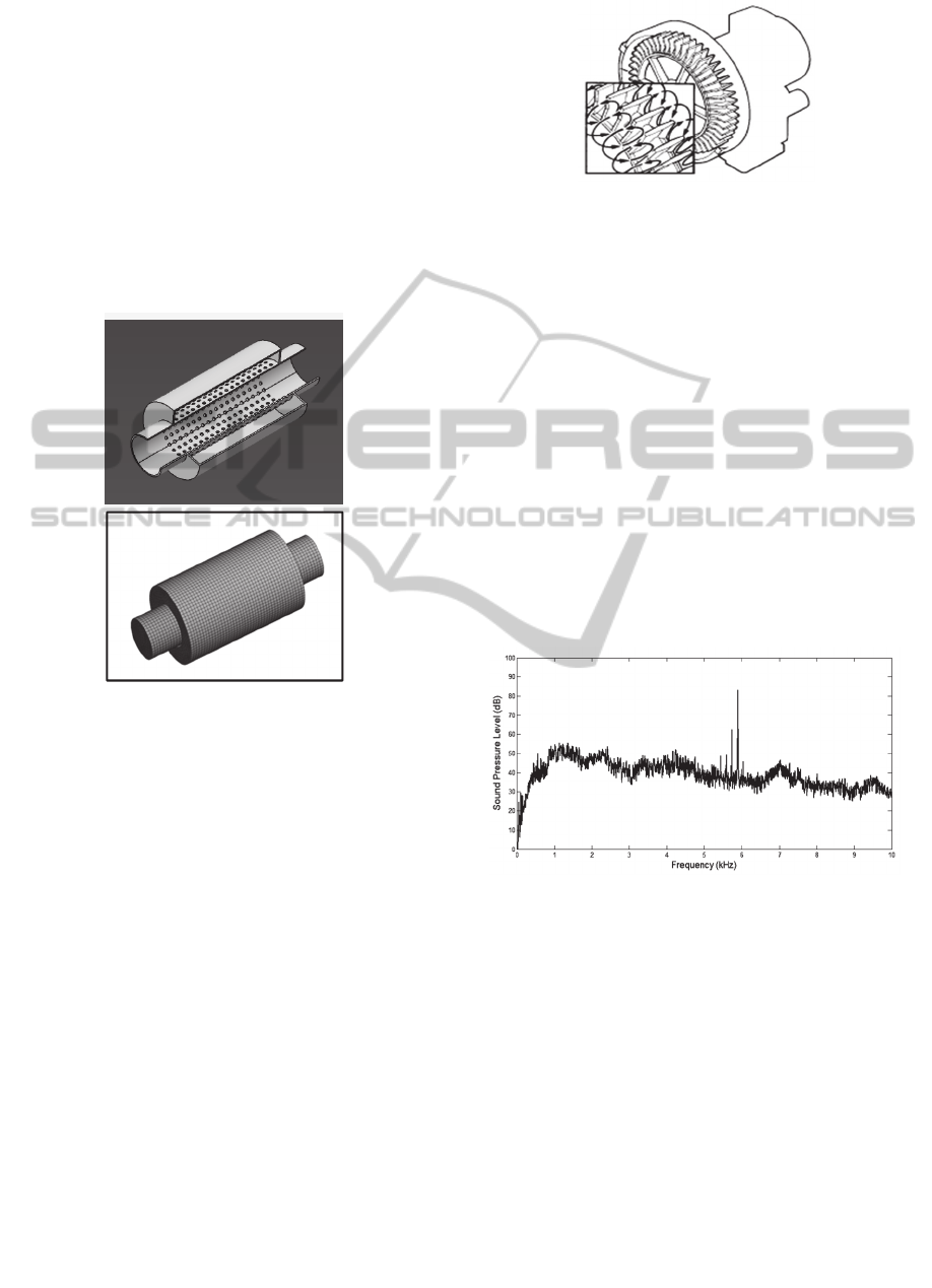
Figure 1: Perforated muffler.
2.2 Methods to Evaluate TL
2.2.1 Transfer Matrix Method
The perforated muffler is consists of parallel coupled
coaxial duct. The two ducts are joined together by a
perforated section of length L
s
. The coaxial duct has
constituent sub-components with straight parts and
parts with holes, respectively. The acoustic pressure
,
,
,
and volume velocity
,
,
,
at the
left end of the coaxial duct can be related with the
acoustic pressure
,
,
,
and volume velocity
,
,
,
at the right ends of the coaxial duct in
the matrix form as
,
,
,
,
∏
,
,
,
,
(2)
Here
and
correspond to transfer matrices of
sub-components with straight parts and parts with
holes, respectively. means the number of the
sub-components. Considering the impedance
regarding to the relation of the pressure difference
and volume velocity through each hole, the pressure
and volume velocity at the inlet of the muffler can
be related to the pressure and volume velocity at the
outlet as
,
,
,
,
(3)
where
is the overall transmission matrix. Here
the impedance at each hole can be determined using
the empirical formula in the reference (Sullivan,
1978)
610
0.75
(4)
where ρ,c,
and are density of air, speed of
sound, hole diameter and acoustic wavenumber at a
given frequency, respectively. The detailed
description in the formulation of the transfer matrix
can be referred in the reference (Sullivan, 1979).
From the relation in Equation TL can be evaluated
as
TL 20log
1
2
|
|
(5)
where
, 1,2 is the corresponding element
of the transfer matrix.
/
and
/
mean the characteristic impedance of two duct with
section area
and
, respectively. The transfer
matrix method is generally used with the assumption
of linear sound propagation of a plane wave in the
muffler. The plane wave limit of a circular duct
corresponds to the case below the cut-off frequency
(Eriksson, 1980) with the first asymmetric mode
that is
,
0.586/
(6)
On the other hand, the first circularly symmetric or
radial mode generated at cut-off frequency is
expressed as
,
1.22/
(7)
2.2.2 Finite Element Method
Numerical simulation methods play an increasingly
important role in the design of mufflers as well as
other NVH applications. FEM offers an
advantageous combination of modelling flexibility,
computational efficiency and result accuracy.
Comparing to the boundary element method (BEM),
FEM allows modelling more complex physics of
acoustics considering multiple fluid domains, sound
propagation in a mean flow and effects of
temperature gradients in a fluid medium. FEM can
be especially used to design of mufflers to reduce
relatively high frequency noise considering the
higher modes above the cut-off frequency as well as
to design the mufflers with relatively complex
shapes.
The linear wave equation for perfect gas with no
damping is
1
(8)
At each frequency in the interested frequency range
that equation (8) becomes Helmholz’s equation at a
as
(9)
where means the acoustic wavenumber at the given
frequency. The three dimensional acoustic domain
DesignofaPerforatedMufflerforaRegenerativeBlowerUsedinFuelCellApplication
489
of the muffler is divided into elements in Figure 2.
The variational formulation of the muffler problem
allows to formulate the discretized equation of linear
systems of algebraic equations as
A
(10)
where
A
,
and f are the coefficient matrix,
sound pressure amplitude vector of nodal values and
forcing function vector of nodal values, respectively.
In the present muffler problem, f is only a non-
zero value at the inlet pipe according to Dirichlet
boundary condition with unit pressure.
Figure 2: Structural shape and finite element model of a
muffler.
In this study, the finite element method approach is
done by a commercial FEM program ACTRAN of
MSC software company. For more efficient way to
model perforation of the muffler, meshes on the
perforated tube are replaced by the two inner and
outer concentric surfaces with acoustic transfer
admittance. For the acoustic transfer admittance, the
transfer admittance of the perforated plate (Mechel,
2008) with the same perforation pattern of the
perforation tube is used.
3 ANALYSIS
3.1 Blower Noise Characteristics
The noise source considered in this research is a
regenerative blower operating with high pressure
rise at low flow capacity shown in Figure 3 (Lee et
al., 2013). It is widely used in various applications
Figure 3: Regenerative blower.
The noise source considered in this research is a
regenerative blower operating with high pressure
rise at low flow capacity shown in Figure 3
(Lee et
al., 2013)
. It is widely used in various applications
including fuel cell applications. One of main
shortcomings of the regenerative blower is high
noise level. The flow inside the regenerative blower
shows typically helical-toroidal motion where fluid
rrotates in and passes along the space between
rotating impeller blades and fixed side channels. It
generates two kinds of noise components such as
discrete frequency noise at BPF and the broadband
noise distributed over wide frequency range which is
produced due to inflow turbulence. Figure 4 shows
the typical pattern of noise spectrum measured from
the regenerative blower. Here BPF corresponds to
5800 Hz.
Figure 4: Noise spectrum of a regenerative blower.
3.2 Verification of the Methods
In order to verify the methods to evaluate TL of the
muffler, the transfer matrix method and FEM have
been applied to evaluate TL of the perforated
muffler model in reference (Sullivan et al, 1978).
The dimensions of the model are 0.257,
0.508,
0.762. The porosity of the tube is
σ 3.8%. The numerical results for TL have been
compared with the corresponding experimental
results in the reference (Sullivan et al, 1978) as
shown in Figure 5. It shows that the two methods
can be used to evaluate TL of the perforated muffler
in good agreement with the experimental results.
SIMULTECH2015-5thInternationalConferenceonSimulationandModelingMethodologies,Technologiesand
Applications
490
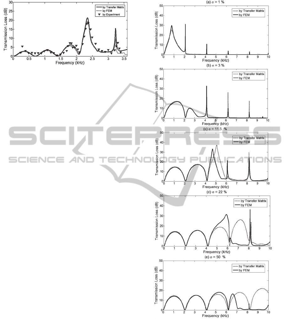
Figure 5: Comparison of the numerical results of TL of the
perforated muffler by transfer matrix method and FEM
with corresponding experimental results.
3.3 TL Characteristics of a Perforated
Muffler
TL of the perforated muffler is dependent on design
variables such as inner diameter
and outer
diameter
, porosity σ, total length . The inner
diameter
is determined to be fitted to the outer
diameter of the blower. The outer diameter
is
determined considering the cutoff frequencies in
Equations (6) and (7) although the transmission loss
performance is increased by increasing the cross-
sectional area ratio between the inlet and outlet ducts,
The initial design length of the muffler can be
determined considering the axial modal frequencies
of the cavity itself as fn
c/2L
1,2,⋯ and
TL pattern of the corresponding simple expansion
chamber composed of the outer duct without the
inner duct. It leads to decision of the initial data for
0.019,
0.06 and 0.083. The
corresponding cut-off frequencies are
,
3320 and
,
6913.The dependence of
TL on the porosity of the muffler is shown in Figure
6. Figure 6(a) also shows a comparison of TL result
obtained by FEM with TL result obtained by the
transfer matrix method with the dependence of the
porosity. The comparison shows some differences
between two results especially above the cut-off
frequency
,
3320 as shown in Figure
6(c)-(e). This phenomenon is shown more clearly as
the porosity is increased. It is because TL results
obtained by FEM includes the contribution of all
higher modes while the only plane wave is
considered in the transfer matrix method. Figure 6(a)
shows that a peak at an annular cavity resonator
resonance is generated about at 800 Hz and clearly
separated from peaks of cavity axial modal
frequencies in higher frequency region. As the
porosity is increased in Figures 6(b)-(e), two peaks
related the annular cavity resonance and the cavity
modal frequency tend to merge and strongly coupled.
Figure 6: Transmission loss obtained by FEM ( and
transfer matrix method ( ⋯ with dependence on the
porosity.
One can find there is an optimum porosity at which
two peaks merge into a single peak having relatively
broad transmission loss at a particular frequency.
When the optimum porosity as σ 22%, the
corresponding single peak is generated at 5800
as shown in Figure 6(d). The peak is also found at
DesignofaPerforatedMufflerforaRegenerativeBlowerUsedinFuelCellApplication
491
BPF 5800 Hz in the noise spectrum of the
regenerative blower as shown in Figure 4.
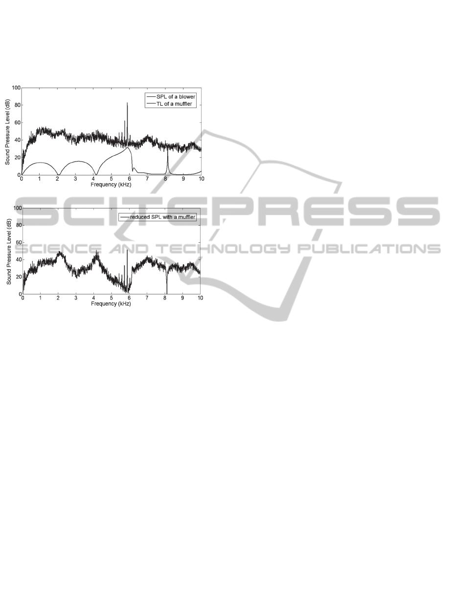
4 RESULTS
(a)
(b)
Figure 7: (a) blower noise spectrum and TL of the
designed perforated muffler and (b) reduced noise
spectrum.
The regenerative blower generates the noise of
overall sound pressure level (SPL) 84 dB(A) with
the frequency spectrum shown in Figure 7(a), that
has two kinds of noise components such as discrete
frequency noise at BPF 5800Hz and the broadband
noise distributed over wide frequency range. In
order to effectively reduce the discrete frequency
noise at BPF, the perforated muffler with the
porosity σ 22% is designed and attached. TL of
the muffler is evaluated over the frequency range
between 0 and 10kHz is as shown in Figure 7(a).
The overall SPL of 84 dB(A) is expected to be
reduced to 72 dB(A) by attaching the perforated
muffler as shown Figure 7(b) that represents the
reduced noise spectrum by attaching the perforated
muffler to the regenerative blower.
5 CONCLUSIONS
A perforated muffler has been designed to reduce a
high noise level that is generated from a regenerative
blower used in fuel cell applications. In order to
effectively reduce discrete frequency noise
component at high frequency 5800 Hz, the design
parametric study has been performed using transfer
matrix method and FEM. It is implemented to design
the perforated muffler that effectively reduces the
high noise level. The overall SPL of 84 dB has been
expected to be reduced to 72 dB by attaching the
perforated muffler. Further research is expected to
experimentally verify the design results and to
evaluate the contribution of porous material inserted
inside the coaxial duct of the perforated muffler to
more reduction of the blower noise.
ACKNOWLEDGEMENTS
This work was supported by the Development of the
Regenerative Blower for fuel cell application of the
Korea Institute of Energy Technology Evaluation
and Planning (KETEP) grant funded by the Korea
government Ministry of Knowledge Economy.
REFERENCES
Lee, C., Kil, H. G., Kim G.C., Kim, J. G., Ma, J. H.,
Chung K. H., 2013. Aero-acoustic Performance
Analysis Method of Regenerative Blower, Journal. of
Fluid machinery (in Korean), 16(2).
Crocker, J. W., M. J.,1978. Analysis of concentric
resonators having partitioned cavities, Journal of
Acoustical Society of America, 64(1).
Sullivan, 1979. A method for modelling perforated
muffler components. I. Theory, Journal of Acoustical
Society of America, 66(3).
Munjal, M. L., 1987. Acoustics of ducts and mufflers with
application to exhaust and ventilation system design,
John Wiley & Sons.
Wu, T. W., Wan. G. C., 1996. Muffler performance
studies using a direct mixed-body boundary element
method and a three-point method for evaluating
transmission loss. ASME Transaction, Journal of
Vibration and Acoustics, 118.
Saf., O., Erol, H., 2010, On acoustics and flow behavior of
the perforated mufflers, 17
th
International Congress
on Sound & Vibration.
Erikson, L. J., 1980. Higher order mode effects in circular
ducts and expansion chambers, Journal of Acoustical
Society of America, 66(3).
Mechel, F. P., 2008. Formulas of Acoustics, Springer, 2
nd
edition.
SIMULTECH2015-5thInternationalConferenceonSimulationandModelingMethodologies,Technologiesand
Applications
492
