
A Taxonomy of Distribution for Cooperative Mobile Manipulators
Andreas Schierl, Andreas Angerer, Alwin Hoffmann, Michael Vistein and Wolfgang Reif
Institute for Software and Systems Engineering, University of Augsburg, Augsburg, Germany
Keywords:
Mobile Robots, Cooperative Manipulators, Software Distribution, Robot Architectures.
Abstract:
Simple robot applications can be run on a single computer, but when it comes to more complex applications or
multiple mobile robots, software distribution becomes important. When structuring mobile robot systems and
applications, distribution has to be considered on various levels. This paper proposes to distinguish between
real-time level, system level, application level and regarding the world model. Advantages and disadvantages
of distribution on each level are analyzed, and examples are given how this distribution is realized in the
robotics frameworks OROCOS, ROS and the Robotics API. The results are demonstrated using a case study
of two cooperating youBots handing over a work-piece while in motion, which is shown in simulation as well
as in real life.
1 INTRODUCTION
With service robotics getting more and more im-
portant, robot demand has extended from stationary
robots in factory automation towards mobile robot
systems. Thus, the topic of mobile robotics has be-
come important, and a lot of research has been per-
formed. However, in some cases a single mobile
robot is not sufficient to execute a task or deal with all
problems. Once multiple robots are to work together,
cooperative mobile manipulators become important,
which poses new challenges.
Already in the 1990s, Dudek et al. (1996) and Cao
et al. (1997) independently described a classification
for cooperative mobile robotics. Dudek et al. (1996)
defined a taxonomy for multi-agent mobile robotics,
where such a system can be e.g. differentiated by the
number of agents, the communication range, topol-
ogy and bandwidth as well as the reconfigurability
and the composition of homogeneous or heteroge-
neous agents. Similarly, Cao et al. (1997) defined re-
search axes in cooperative mobile robotics such as the
differentiation, the communication structure or differ-
ent types of modeling other agents. Moreover, they
made a distinction between centralized and decentral-
ized control in the software for mobile robots. Later,
Farinelli et al. (2004) added a classification based
on coordination, where they compared cooperation,
knowledge, coordination and organization of agents
in multi-agent systems. This classification defines
aware multi-robot systems where each robot knows
that it is cooperating with other robots. Concentrat-
ing on aware systems, this paper analyzes which dis-
tributed software architecture can be used.
However, there is not only one distributed soft-
ware architecture that is possible in cooperative mo-
bile robotics. From our point of view, there are dif-
ferent levels and aspects in the software architecture
of a multi-robot system that can be distributed, rang-
ing from the application level to low-level real-time
device control. Typical early software architectures
such as 3T (cf. Bonasso et al., 1995) include reac-
tive behavior as well as planning and execution, but
are limited to single robot systems. The decision to
distribute the software solution on one of the men-
tioned levels may affect the other levels and the com-
plexity of the solution. Every possible solution, i. e.
the chosen distributed software architecture, has its
advantages but also its shortcomings that must be
considered. In robotics systems, component based
software frameworks are commonly used (cf. Brugali
and Shakhimardanov, 2010), for example ROS which
facilitate transparent distribution (cf. Quigley et al.,
2009). However, although communication between
distributed components is easy using these frame-
works, the decision about distribution as well as the
assignment of responsibilities to certain components
affects the overall capabilities of the solution (e.g.
support for hard real-time).
In this paper, we introduce a taxonomy for dis-
tributed software architectures in cooperative mobile
robotics. We are interested in finding a generalized
74
Schierl A., Angerer A., Hoffmann A., Vistein M. and Reif W..
A Taxonomy of Distribution for Cooperative Mobile Manipulators.
DOI: 10.5220/0005541700740083
In Proceedings of the 12th International Conference on Informatics in Control, Automation and Robotics (ICINCO-2015), pages 74-83
ISBN: 978-989-758-123-6
Copyright
c
2015 SCITEPRESS (Science and Technology Publications, Lda.)
representation and description of distributed robotics
systems. Hence, this taxonomy can be used to clas-
sify and compare the software architectures of dis-
tributed robotics systems. Additionally, we give ad-
vantages and disadvantages of applying distribution
on different levels. It is important to be able to com-
pare distributed robotics systems as the chosen soft-
ware architecture often influences or sometimes even
determines the complexity of the solution. However,
over-simplification can sometimes lead to unrealistic
solutions that will fail in real life.
Section 2 describes a case study using cooperat-
ing KUKA youBots as mobile manipulators, which is
used as reference example throughout the paper. A
taxonomy that separates different levels for structur-
ing software for (mobile) robots is given in Section 3.
Subsequently, the different possibilities of distribut-
ing software using these levels, as well as the advan-
tages and disadvantages are discussed in Section 4.
To show the general validity of the taxonomy, the dis-
tribution possibilities are explained using three differ-
ent software frameworks. Experimental results about
different solutions of the case study are presented in
Section 5. Section 6 concludes this paper and gives
an outlook.
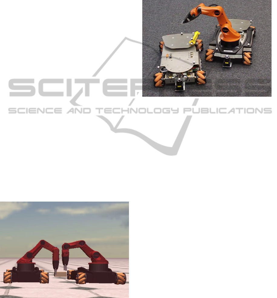
2 CASE STUDY
As a case study for cooperating mobile robots, a sce-
nario containing two KUKA youBots (cf. Bischoff
et al., 2011) is used. In this scenario, the robots phys-
ically interact with each other to transfer a work piece
from one youBot to the other.
Figure 1: Cooperation of two youBots in simulation.
This scenario is inspected in different levels of dif-
ficulty. The first variant runs in simulation (cf. Fig-
ure 1), where both robots can be coordinated in real-
time, exact position information is available and all
control inputs and trajectories are exactly followed.
For this variant, first an easy case is analyzed where
the first robot is standing still, and afterwards a more
complex case follows where the workpiece transfer
happens while both robots are moving.
Figure 2: Cooperation of two real youBots.
As some of the assumptions made for simulation
case are not valid for real robots, a second variant
with real youBots is analyzed (cf. Figure 2). There, a
youBot platform (left, without arm) is initially carry-
ing a workpiece, which is then picked up by the sec-
ond youBot (right) while both youBots are moving.
The youBots and the workpiece are tracked externally
using a Vicon optical tracking system, so precise po-
sition information is available.
However, the the concepts presented in the follow-
ing sections are not specific to this use case with mo-
bile robots, but also apply to other cooperating robots
such as teams of industrial robots that produce goods
in an automation plant.
3 SOFTWARE STRUCTURE FOR
DISTRIBUTED ROBOTS
When designing a software architecture for a dis-
tributed robot scenario, we propose to group the soft-
ware components into different layers as illustrated in
Figure 3.
Each of the hardware devices present in the robot
solution is represented and controlled by a device
driver: The component that communicates with the
hardware device through the vendor-specific inter-
face. The device driver is responsible for exchang-
ing data with the surrounding software components.
It has to derive control inputs and forward them to the
device, as well as receive feedback from the device
and make it available to other software components.
ATaxonomyofDistributionforCooperativeMobileManipulators
75

DeviceDevice Driver
Real-Time Context
System
Application World Model
Dynamic
Knowledge
Static
Knowledge
works on
controls
knows
*
*
*
*
Figure 3: Software structure for distributed robots.
Each device driver can belong to a real-time con-
text: The components between which data transfer
and coordination occurs with given timing guaran-
tees. Depending on the implementation, the real-time
context can contain only one device, or span over
multiple devices. Within a real-time context, reac-
tions to events or the processing of sensor data can be
guaranteed to happen before a given time limit (hard
real-time). This allows to handle safety-critical situ-
ations that require timing guarantees (e.g. to stop the
robot if an obstacle occurs), or to execute precise be-
haviors (such as actions that happen at a given point
on a trajectory).
Above the real-time level, one or multiple real-
time contexts belong to a system: The components
between which all knowledge is shared. Within one
system, all components are allowed to access each
other’s data, and to communicate with and send com-
mands to each other. This allows components to di-
rectly include other components’ data into planning
or computation, though no real-time guarantees are
given (unless handled within one real-time context).
A system can span multiple computers, as long as re-
liable means of communication exist to facilitate the
required data transfer.
To perform a desired task, one or more systems
can be used in an application: The components
that coordinate a work flow executed by the systems.
Within an application, data is read and commands are
sent to the controlled systems, so that the correspond-
ing devices execute the task. However, if data from
one system is required for an action in another sys-
tem, it is the responsibility of the application or the
deployment to facilitate the required data transfer, as
there is no concept of implicit shared data between
systems. The overall behavior of cooperating robots
results from the interplay of all applications that co-
ordinate the robots.
Each application performs its work based on its
world model: The knowledge about the controlled
devices and systems, as well as the environment in-
cluding other (cooperating) devices. This includes
geometric information such as positions and orien-
tations of the relevant objects, as well as physical
data (such as mass and friction), shape data (such as
3D models for visualization or collision checks), se-
mantics and ontologies. Information from the world
model can be stored and used in applications, sys-
tems or real-time contexts, and can also be shared
between different applications and systems. Struc-
turally, the world model data can be differentiated into
dynamic and static knowledge, with static knowledge
(e.g. maps, shapes and ontologies) being valid every-
where, while dynamic knowledge (such as positions
and sensor data) may be known in only one system or
be different in different systems.
4 DISTRIBUTING THE
SOFTWARE
Depending on the requirements and technical limita-
tions of the robot solution, the size and distribution
of real-time contexts, systems and applications and
thus the structure of the software can vary. This sec-
tion discusses different design decisions concerning
this structure based on the examples of the case study
described in Section 2 and using the three popular
frameworks OROCOS, ROS and the Robotics API.
OROCOS as a component framework mainly targets
control systems with real-time guarantees (cf. Bruyn-
inckx, 2001). The main focus of ROS is to be a
component framework with transparent distribution,
which over time has collected a large amount of al-
gorithms as reusable components (cf. Quigley et al.,
2009). The Robotics API focuses on high-level robot
programming using modern programming languages
(such as Java) while still providing real-time guaran-
tees (cf. Angerer et al., 2013).
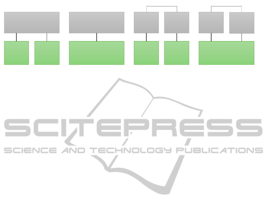
4.1 Real-time Level
First, the existing hardware devices and device drivers
have to be grouped into real-time contexts. In the mo-
bile manipulator example of Section 2 this is mainly
the two youBots, where we will concentrate on two
platforms and one or two arms. Generally speaking,
there are four different choices for this situation (cf.
Figure 4):
In the smallest case (Real-time Context A in Fig-
ure 4), the device driver software is written without
real-time in mind. In this case, the real-time context
ICINCO2015-12thInternationalConferenceonInformaticsinControl,AutomationandRobotics
76
Real-time
Context B
Base
Driver
youBot
Platform
Arm
driver
youBot
Arm
Real-time
Context A
Real-time
Context C
Base
Driver
youBot
Platform
Arm
Driver
youBot
Arm
Real-time
Context D
Left
Base
Driver
Left
Platform
Left
Arm
Driver
Left
Arm
Right
Base
Driver
Right
Platform
Right
Arm
Driver
Right
Arm
Figure 4: Different variants of real-time contexts.
only spans the firmware (if real-time capable) or con-
troller (digital or analog) present in the device itself.
For the youBot Arm, this could mean that only the
position control mode of the arm motor controllers is
used, where it is sufficient to give one joint configu-
ration that the robot is expected to move to. While
easy to implement, no synchronization between the
joints or support for precise Cartesian space motions
is possible, and no guarantees can be given regarding
the interpolation quality of user-defined trajectories or
the timing of reactions to events (unless supported di-
rectly by the device).
In the next case (Real-time Context B), the device
driver and the communication with the device is im-
plemented in a real-time capable fashion. This re-
quires to use a real-time operating system and more
care when implementing the device driver, but allows
to execute precise custom trajectories and handle sen-
sor events with timing guarantees. For example, a
real-time capable driver running at 250Hz could be
implemented for the youBot Platform on a real-time
operating system such as VxWorks or Xenomai. It
can provide the motor controllers with smooth control
set points for velocity or torque control, which allows
precise user-defined trajectories, or to implement cus-
tom feed-forward or feedback control laws. However,
as a drawback only information that is provided by
the device itself can be included in the control law.
For example only the wheel position can be controlled
exactly, but the position of the entire robot in Carte-
sian space is inaccurate (due to wheel slip and other
factors limiting odometry precision), and the platform
motion cannot be synchronized with the arm motion.
Increasing the context, multiple devices can be
combined (cf. Real-time Context C), up to all devices
that are physically connected to the controlling com-
puter. Both the youBot arm and the platform, which
are connected to the onboard computer via EtherCAT,
can be controlled from a real-time capable software
on a real-time operating system. This way, coordi-
nated motions between platform and arm are possible,
that are realized through the 5 joints of the arm and
the three degrees of freedom provided by the omni-
directional platform. This for example allows Carte-
sian space motions of the end-effector relative to a
point in Cartesian space known to the youBot (such
as the position where the youBot started – called the
odometry origin – assuming that odometry exactly
provides the current position relative to this origin
based on wheel rotations). Additionally, one device
can react to events that occur at other devices or are
detected by other sensors. However, to be able to
specify these reactions, either this part of the soft-
ware has to be changed for a specific application, or a
flexible specification language is required (cf. Schierl
et al., 2012, 2013).
To enable easy cooperation between multiple
robots, the devices of all robots could be combined
into one real-time context (cf. Real-time Context D).
However, if the corresponding devices are connected
to different PCs, real-time communication between
the PCs is required. For stationary robots such as
robot arms or automation systems in a factory, or
complex mobile robot systems with multiple com-
puters on board (such as the WillowGarage PR2 or
the DLR Justin), this is possible through Ethernet
or field buses like Ethercat. In the automation do-
main, standard equipment such as PLCs are used,
while in robot research software frameworks such as
aRDx (cf. Hammer and Bauml, 2013) or Orocos (cf.
Bruyninckx, 2001) are preferred. But between mobile
robots, using a wired connection usually is no option,
and standards for general purpose real-time capable
wireless connections are not yet common, so provid-
ing a single real-time context is not yet widely us-
able. In summary, while distributing a real-time con-
text over multiple computers can improve the scala-
bility of the solution (w.r.t. processing power or de-
vice connectivity), the need for deterministic commu-
nication implies special requirements (such as field
bus hardware or dedicated networks) that make the
solution more complex or expensive.
Depending on their focus, different robot frame-
works offer more or less support for large real-time
contexts:
• In ROS, real-time contexts with one device (vari-
ATaxonomyofDistributionforCooperativeMobileManipulators
77
youBot
Arm
Context (A)
System 2M
youBot
Platform
Context (B)
youBot
Context (C)
System 2S
Left
youBot
Context (C)
System 3M
Right
youBot
Context (C)
Left and Right
youBot
Context (D)
System 3S
youBot
Platform
Context (B)
System 1S
Single Device Systems Single youBot Systems Team Systems
Single
Context
Systems
Multi
Context
Systems
Figure 5: Different variants of systems.
ants A and B) are widely used, when a single de-
vice is encapsulated into a ros node, providing an
interface to execute the required local commands.
Sometimes multiple devices (such as a youBot
arm and platform) are combined into one node,
however this leads to higher coupling.
• In OROCOS usually most devices are combined
into one real-time context, because the OROCOS
frameworks targets real-time capable component
systems with device drivers implemented in C++
on a real-time operating systems such as RTAI or
Xenomai. When using multiple mobile robots,
sometimes a wired connection (cf. Klotzb
¨
ucher
et al., 2013) is used to ensure one real-time con-
text. In other cases, other communication frame-
works such as ROS provide non-real-time com-
munication between the distributed robots, thus
introducing multiple real-time contexts.
• Using the Robotics API, the Robot Control Core
(cf. Vistein et al., 2010) is implemented in C++ for
Xenomai and includes real-time capable drivers
for devices connected to the corresponding com-
puter. This way, all devices physically connected
to the computer can form a real-time context. Fur-
thermore, plans exist to extend the implementa-
tion to support multiple Robot Control Cores as
a single real-time context, given a deterministic
(wired) connection exists.
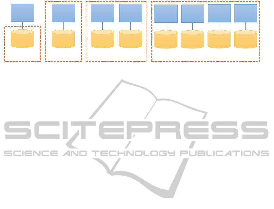
4.2 System Level
Proceeding to the system level, real-time contexts can
be grouped into systems. When looking at the number
of real-time contexts involved, two options exist on
the system level (cf. Figure 5):
As a minimal case, each real-time context has its
own system (cf. System 1S, 2S and 2S in the Figure).
But it is also possible to combine multiple or even
all real-time contexts into a single system (cf. System
2M and 3M). Another grouping option is based on the
set of devices combined into the system. This can be
just one device (e.g. one platform in System 1S), all
devices of one youBot (cf. System 2S and 2M) or all
youBots (cf. System 3S and 3M).
Using a big system spanning all robots has the ad-
vantage of simplifying application programming or
deployment: All the data that any component might
need is made available everywhere in the system, so
no manual data transfer is required. This especially
covers the world model – within one system, a consis-
tent world model is possible, because the best knowl-
edge about the world is available to every component.
However, there can be various reasons to use mul-
tiple systems: The sheer amount of data present in
a big (multi) robot system can be a technical reason.
Scalability can be limited by the management over-
head induced by the data transfer between a great
amount of components, and the addressing or map-
ping of data to components can become problematic.
Furthermore, network bandwidth or reliability can be
a limiting factor. In particular, this can be a problem
when multiple robots are used that cooperate in vary-
ing teams. While for constant teams the correspond-
ing robots could be joined into one system, varying
teams quickly increase the required system size as all
robots that might work together in a team at any time
have to be within the same system.
But also more political reasons can opt for the sep-
aration into multiple systems, if cooperating robots
belong to different people or parties. In this situa-
tion, not everyone might want to provide access to
all of the robot’s data, or allow everyone else to con-
trol the robot. Then, matters of trust or access con-
trol become important that do not fit into the share-
everything theme of a system. However, these reasons
do not occur between the different devices within one
ICINCO2015-12thInternationalConferenceonInformaticsinControl,AutomationandRobotics
78
Left
youBot
System
Right
youBot
System
Application
A
youBot Team System
Application
B
Left
youBot
System
Right
youBot
System
App
C1
youBot Team System
App
C2
App
D1
App
D2
coordination coordination
Figure 6: Different variants of applications.
robot (such as the youBot), so the grouping option 1S
with just a platform only makes sense if the platform
is used without an arm.
Looking at the software frameworks, the different
focus becomes obvious:
• In ROS, one system includes all nodes that run
using the same ROS master. In this situation, all
these nodes can subscribe to any data published
by other nodes, and post messages or actions. The
world model includes transformation data as pro-
vided by the tf service, as well as robot models
and data published by other nodes.
• OROCOS as a framework concentrates on one
real-time context and does not per se contain fea-
tures for non-real-time communication, however
often ROS is used to combine multiple real-time
contexts into one common system that allows for
non-real-time communication and data sharing.
World models are usually implemented as compo-
nents in an application dependent manner, which
can include geometry, semantics and history (cf.
Blumenthal et al., 2013).
• In the Robotics API, the system term refers to the
concept of a RoboticsRuntime, which represents
one real-time context and makes the data avail-
able – to applications in a non-real-time way as
well as to other devices in the same context for
real-time reactions. The frame graph (cf. Angerer
et al., 2013) including semantic information (such
as the type of relation between frames, if they are
static, temporary or have a transformation that can
change during execution) and information about
physical objects (such as physics meta data and
shape) serves as a world model that can be used
for planning as well as task execution.
Generally speaking, it is possible to distribute the
corresponding components that form one system onto
different PC systems, as no realtime guarantees are
required on this level. Therefore, standard communi-
cation methods including wireless ones such as WiFi
are applicable, however reliability or bandwidth can
be limiting factors.
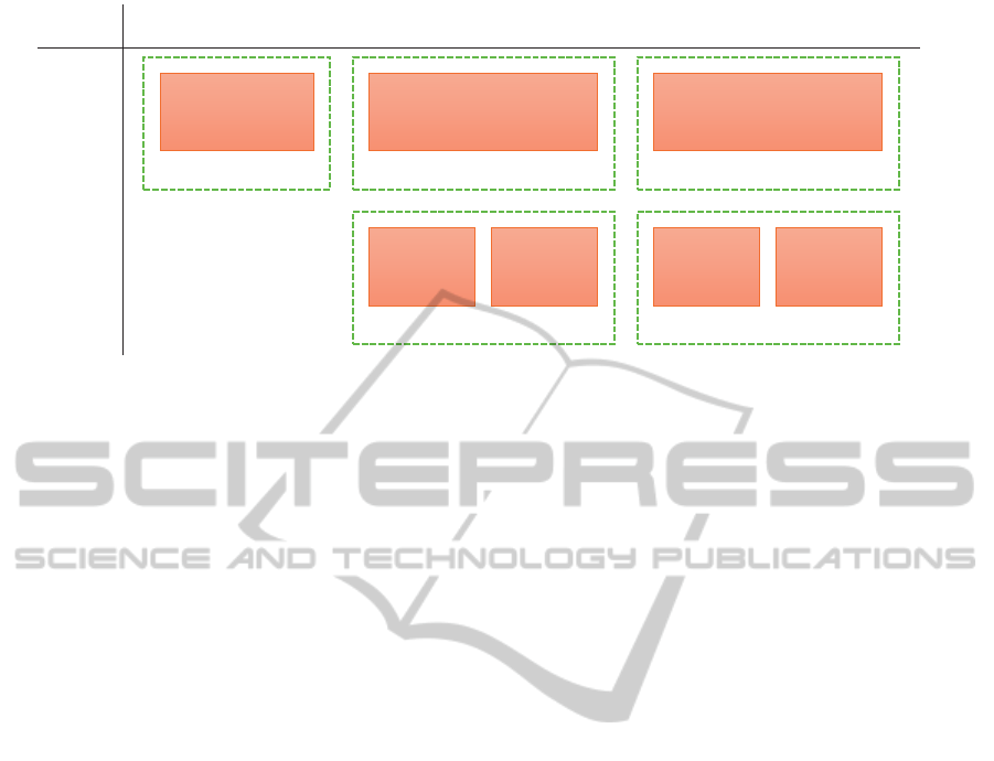
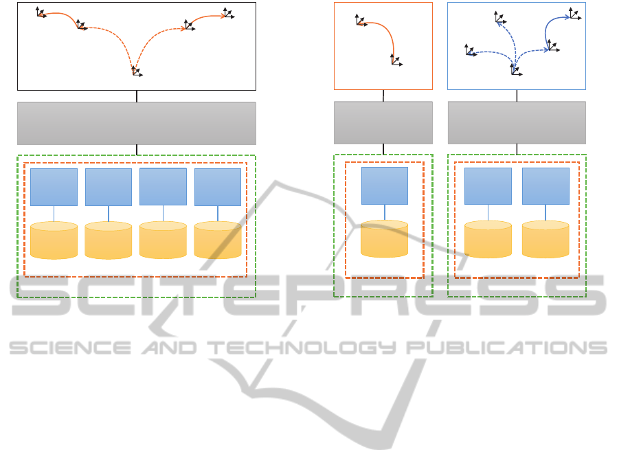
4.3 Application Level
To perform a requested task, one or multiple systems
have to execute actions that are controlled and co-
ordinated by one or multiple applications. Figure 6
gives the different possibilities to structure the appli-
cation(s) for controlling the two youBots.
One way is to control all robots from one appli-
cation (cf. Application A and B). This defines all the
interaction present in the solution in one place and
thus makes it easier to understand. However, if vary-
ing teams are needed in a certain scenario, the cor-
responding application has to coordinate all robots at
the same time. This can become confusing if the con-
current execution of multiple subtasks is encoded in
one control flow or sequential state machine. Thus,
separating concerns into subtasks, one for each team,
should be considered within the application.
Another way is to use multiple applications, e.g.
one for each controlled system (cf. App C1, C2, D1
and D2). This way, changing teams can be imple-
mented by only locally and independently describing
the behavior of each system. However, the applica-
tions have to coordinate, either through explicit com-
munication or through observation of the environment
or other robots. Using separate applications can also
be required for political reasons, as described in the
previous section. In a multi-application cooperation
scheme, however, the resulting behaviour is not easily
understandable by looking at one place, but only by
examining the interaction of the different applications
involved. In the most extreme case, the application
for each robot only implements low-level behaviours,
and the resulting behaviour emerges from the interac-
tion (cf. Mataric, 1993).
Another structuring approach looks at the relation
between applications and systems. It is possible to
control (different devices of) one system from mul-
tiple applications (cf. D1 and D2), one system from
one application (cf. B, C1 and C2) or multiple systems
from one application (cf. A). The software framework
should allow an application that was intended for use
with multiple systems (e.g. A) to also work when all
ATaxonomyofDistributionforCooperativeMobileManipulators
79
corresponding devices exist in one system, while the
distribution aspect on the system and real-time level
is handled by deployment (e.g. through configura-
tion). This may however not be possible the other way
round, if the application relied on having one system
(or even real-time context).
There are various ways to specify applications:
Mainly sequential workflows can well be expressed
as a programming language control flow. For reac-
tive behaviour, model-based approaches such as state
charts or Petri nets can be more appropriate. These
ways of specification are available in different frame-
works, but the support for controlling multiple sys-
tems from one application varies:
• In ROS, Python scripts can be used for sequen-
tial workflows, while SMACH state machines in-
troduced by Bohren and Cousins (2010) allow re-
active behaviour. However, communication with
multiple ROS masters is not natively supported.
To share data between different systems (ros mas-
ters), concepts like multimaster or foreign relay
(cf. Schneider, 2012) can be used that forward
topics between multiple masters and can be used
through deployment. Additionally, supporting
multiple masters is one of the new use cases mo-
tivating ROS 2
1
.
• With OROCOS, control flow can be expressed in
LUA scripts, while complex coordination is pos-
sible using coordination components written in
rFSM as suggested by Klotzbucher and Bruyn-
inckx (2012). Concentrating on one real-time
context, OROCOS also does not provide direct
support for access to multiple systems.
• Using the Robotics API, control flow can be ex-
pressed directly in Java applications, as well as
through state charts using Java state chart li-
braries such as SCXML. It is easily possible to
use multiple systems in one application (as used
by Hoffmann et al. (2014) in the Factory2020
example), and to share limited amount of data
between different systems or applications, either
through common data sources (such as a Vicon
system connected to both youBots through WiFi),
or through explicit direct transfer.
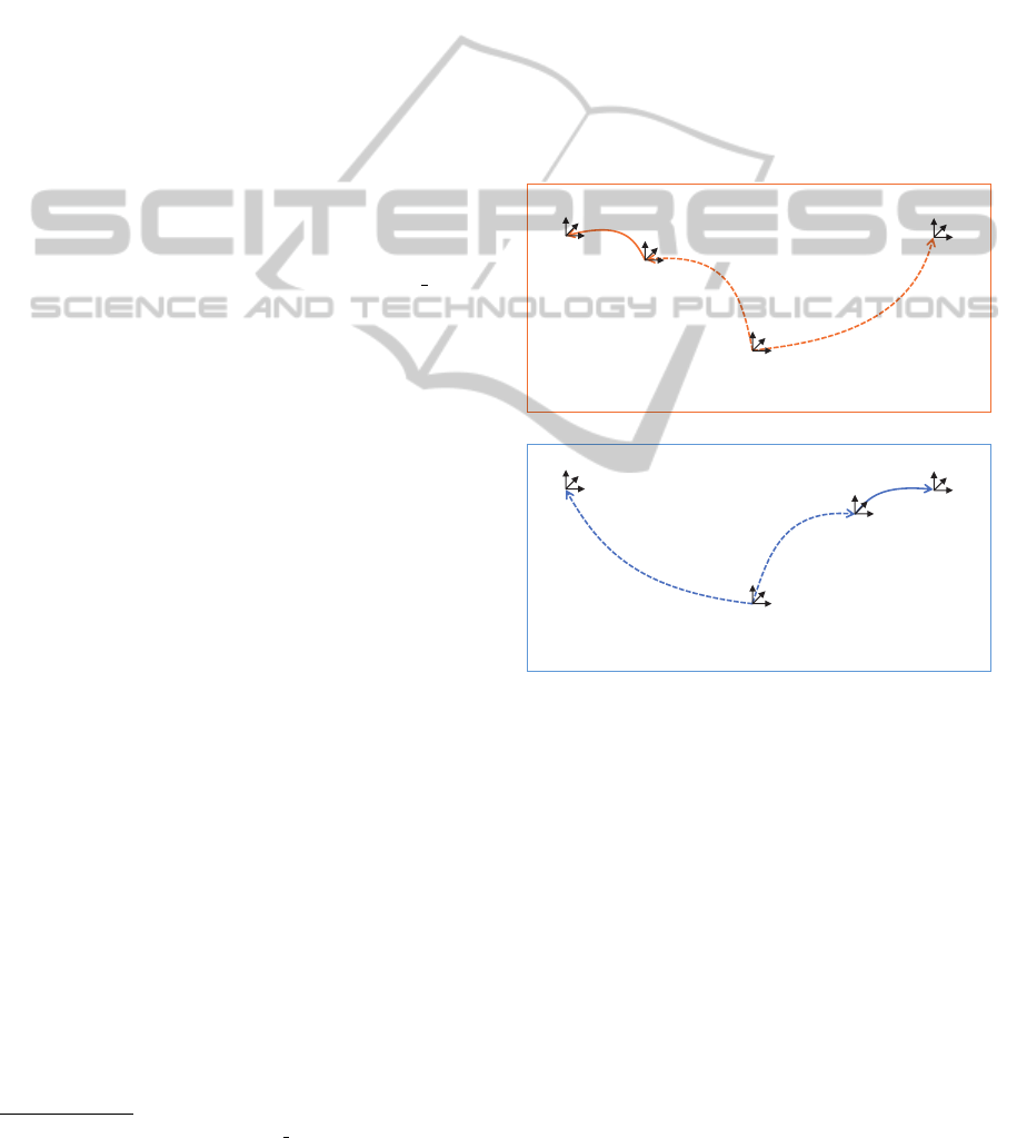
4.4 World Model
If a robot is expected to cooperate with another robot,
it needs the relevant data about that other robot. In
the easiest case, both robots belong to the same sys-
tem, thus the required information is already accessi-
ble. We then call the other robot a controlled robot.
1
http://design.ros2.org/articles/why ros2.html
Once robots from multiple systems are to be co-
ordinated from one application, the world model be-
comes more complex. The information about robots
in other systems can originate from communication or
observation. Either the other system provides (maybe
read-only) access to the information (then we call the
other robot a remote robot), or the information is only
available through observation (thus we have an ob-
served robot). The world model thus has to keep (a
descending amount of) information about controlled
robots, remote robots and observed robots.
In the case of observed and remote robots, some
information (e.g. position of the first robot) is avail-
able in different systems with varying precision, and
has to be organized. Therefore, different world model
structures can be used:
Origin
Left youBot Origin
Right youBot
Left youBot
Origin
Right youBot Origin
Right youBot
Left youBot
Right youBot World Model
Left youBot World Model
L3
L1
L2
R2
R1
R3
Figure 7: Separate world models for multiple systems
One way is to keep one world model per sys-
tem. Figure 7 shows an example of two world mod-
els that can occur using two youBots in two sys-
tems (e.g. with Application A). The figure concen-
trates on geometric information, with coordinate sys-
tems indicating named positions or objects in space
(frames), while arrows represent transformations be-
tween these frames. Solid arrows indicate control-
lable positions, while dashed arrows indicate posi-
tions retrieved through measurement or communica-
tion. Orange arrows (L1 to L3) belong to the system
of the left youBot, while blue arrows (R1 to R3) be-
long to the right youBot system. The frames could be
augmented by additional information such as shape
data, which is omitted here for clarity.
Using separate models has the advantage that mul-
ICINCO2015-12thInternationalConferenceonInformaticsinControl,AutomationandRobotics
80
tiple systems can just use different instances of the
same world model, which allows to re-use models de-
signed for single systems to a large extent. However,
for cooperation a lot of information has to be dupli-
cated, such as models of robots that occur as con-
trolled robot in one and as a remote robot in another
system. Additionally, the different world models have
to be kept consistent. For example, a workpiece that
is grasped and moved in one system also has to appear
as grasped and moved in the other system.
Global World Model
L1
L2
R2
R1
R4
R5
L5
L4
Left youBot
Left youBot Origin
Origin
Right youBot Origin
Right youBot
Figure 8: Using a global world model for all systems.
The second way is to keep one global world model
with all the objects and relations, and to provide ac-
cess to the different transformations or sensor values
for each system (cf. Figure 8). This has the advan-
tage that the world model is always consistent (as far
as topology and static information is concerned, how-
ever different systems can still disagree about frame
transformations), and structural changes performed
in one system are automatically present in other sys-
tems.
However, this scheme lacks flexibility when deal-
ing with observed robots: While a mobile robot can
keep track of its movement since the start through
odometry measurements, an observer has no way to
achieve this information from outside. Thus, the
frame graph contains two transformations about the
robot for controlled and remote robots (R1 and R2 in
Figure 7), while for observed robots only one trans-
formation is available (R3 in Figure 7).
Origin
Left youBot Origin
Right youBot Origin
Right youBot
Left youBot
Mixed World Model
L3
L1
L2
R2
R1
R3
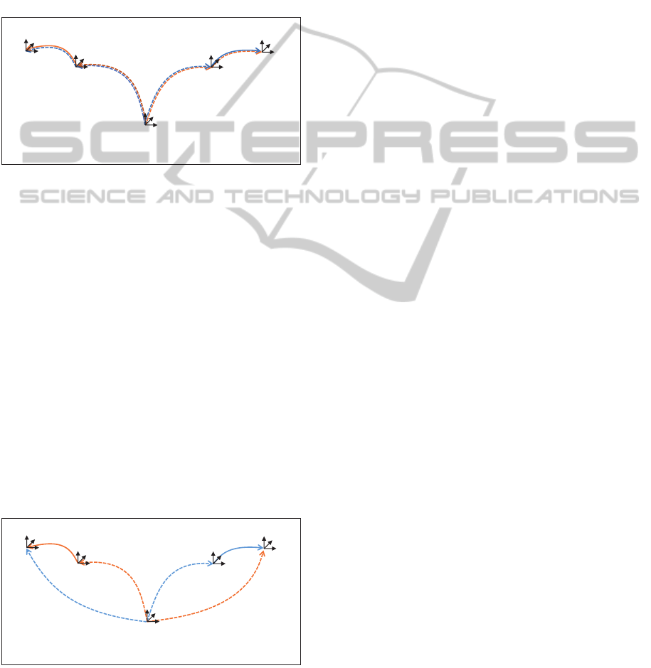
Figure 9: Using a mixed world model scheme.
To solve this problem, we propose a mixed world
model scheme (cf. Figure 9). In a mixed world
model, the static data is shared between all systems,
while dynamic data can be different for each sys-
tem. For example, information about physical ob-
jects (such as the youBot geometry) as well as static
connections (such as the position where the youBot
Arm is mounted relative to the youBot Platform) are
shared. Dynamic connections (such as the position
of the youBot relative to its origin, or the fact that
the youBot is positioned relative to the World Ori-
gin or youBot Origin) can be different for each sys-
tem. Still, in both systems it should be possible to
compute the transformation of the Left youBot to the
Right youBot, using the data and topology present in
each system (and to use it for planning and execu-
tion). This combines the advantages of a shared world
model with the flexibility to include limited observa-
tions, while still allowing the application to address
one youBot in a uniform way.
5 EXPERIMENTAL RESULTS
AND DISCUSSION
The simulation experiments described in the case
study have been performed using the Robotics API as
a framework, using the corresponding simulation and
visualization engine (cf. Figure 10). A single appli-
cation (cf. Application B in Figure 6) was used. This
application controlled a single system (cf. System 3S
in Figure 5) containing a single real-time context (cf.
Real-time Context D in Figure 4). In this real-time
context, both youBot arms and platforms were simu-
lated, as well as the youBot grippers. The application
was programmed in an object-oriented fashion, refer-
ring to the robots and work pieces as software objects
using a single world model and expressing the inter-
action in the control flow of a Java method. The initial
version of the application where the first robot was not
moving during transfer was easily extended into the
second version where both platforms were moving.
This extension mainly consisted of adding commands
to move the first platform, and to make the second
platform synchronize its motion to the position and
movement of the first platform. This showed the sim-
plicity of object-oriented programming and synchro-
nizing robots in the idealized simulation case where
every device belongs to the same real-time context
and can be synchronized, and where exact position-
ing is available.
Transferring the results from simulation to reality,
various changes had to be done. The tests were con-
ducted on the two KUKA youBots available in our
lab, using a Vicon optical tracking system for exter-
nal localization.
ATaxonomyofDistributionforCooperativeMobileManipulators
81
Simulated RT Context
Left
Base
Driver
Left
Platform
Left
Arm
Driver
Left
Arm
Right
Base
Driver
Right
Platform
Right
Arm
Driver
Right
Arm
Simulation System
Simulation Application
Origin
Left youBot Origin
Right youBot Origin
Right youBot
Left youBot
Figure 10: Structure of the simulation application.
A straightforward approach is to combine both
youBots into one real-time context. Thus, the same
distribution scheme like in the simulation case could
be re-used, as could be large parts of the implementa-
tion. However, lacking real-time communication over
wireless networks (cf. Section 4.1), this was not eas-
ily possible. On the other hand, while for stationary
industrial robots adding a common real-time context
spanning both robots greatly simplifies and improves
the precision of physical cooperation, in the mobile
case the gains are less clear. This is because pre-
cise cooperation does not only require exact timing
synchronization, but also exact spatial synchroniza-
tion. For stationary robots, this can be achieved by
appropriate calibration procedures. For mobile sys-
tems, this is in general more problematic due to sen-
sor inaccuracies. External positioning systems like
the Vicon system used here can mitigate this problem.
However, wireless real-time communication becomes
a problem again when it comes to transmitting the po-
sition information to the youBots. Thus, we decided
to choose an alternative distribution approach (cf. Fig-
ure 11): On each youBot’s internal computer an in-
stance of the Robot Control Core was running, which
formed the real-time context (cf. Real-time Context
C in Figure 4) and system (cf. System 2S in Fig-
ure 5 for this youBot’s platform, arm and gripper)
for the corresponding youBot. Vicon tracking data
for both youBots and the workpiece was streamed to
both youBot systems through a WiFi connection from
an external PC running the Vicon software.
Looking at the application level, each youBot was
controlled from a separate application. The motion of
Left RT Context
Base
Driver
Left
Platform
Right RT Context
Base
Driver
Right
Platform
Arm
Driver
Right
Arm
Left System Right System
Joystick
Application
Transfer
Application
Left youBot Origin
Left youBot
Vicon
Right youBot Origin
Right youBot
Left youBot
Workpiece
Figure 11: Structure of the real application.
the platform carrying the workpiece was controlled
through teleoperation (cf. Application C1 in 6). The
other youBot was controlled by a Java method similar
to the one in the simulation case (cf. Application C2
in 6), however both applications used separate world
models (cf. Figure 7). The workpiece and the other
youBot platform were not modeled as Java objects,
but only the Vicon position data was used to syn-
chronize the motion and find the grasp position. The
youBot arm used joint impedance control to mitigate
position inaccuracies. Still, the experiment succeeded
and the work piece could be transferred.
Instead of separate world models, a mixed world
model could have been used, which would be closer
to the (single) world model in the simulation case.
This way, changes to the world model topology (e.g.
the information that the object has been grasped)
would have automatically been transferred to the sec-
ond youBot’s system and static position data would
be known to both youBots. Depending on the trust
level among both youBots, dynamic data could be
exchanged by appropriate deployment using remote
robots (high trust) or merely by observation, e.g. us-
ing the Vicon system in a deployment with observed
robots (low trust).
6 CONCLUSIONS AND
OUTLOOK
In this paper, we introduced four levels for structuring
the software for distributed robot applications: real-
time, system, application and the world model. The
ICINCO2015-12thInternationalConferenceonInformaticsinControl,AutomationandRobotics
82

structure on the different levels can be used and com-
bined independently, motivated by technical as well
as political constraints.
The different options for structuring have been ex-
plained based on a case study of cooperating mobile
manipulators and various robot frameworks, and eval-
uated in simulation and real world on a setup with two
KUKA youBots. In the example applications, differ-
ent ways to distribute the software on different lev-
els have been shown, and the advantages and draw-
backs for the given scenario have been shown. Over-
all, it became clear that there is not a single optimal
way of structuring and distributing the software. The
taxonomy presented in this work will hopefully be a
starting point that can help developers in designing
and discussing their software architecture. Based on
non-functional requirements to the developed solu-
tion (like reactiveness, synchronization quality, data
privacy, trust, ...), the choice of the appropriate distri-
bution scheme and framework(s) for implementation
should become easier.
As next steps, we plan to implement the men-
tioned other ways of distribution and to evaluate the
gains for the given scenario. This especially includes
the use of a mixed world model, as well as ways to
share a world model between multiple applications or
to synchronize relevant structural changes.
REFERENCES
Angerer, A., Hoffmann, A., Schierl, A., Vistein, M., and
Reif, W. (2013). Robotics API: Object-Oriented Soft-
ware Development for Industrial Robots. J. of Soft-
ware Engineering for Robotics, 4(1):1–22.
Bischoff, R., Huggenberger, U., and Prassler, E. (2011).
KUKA youBot - a mobile manipulator for research
and education. In Robotics and Automation (ICRA),
2011 IEEE International Conference on, pages 1–4.
Blumenthal, S., Bruyninckx, H., Nowak, W., and Prassler,
E. (2013). A scene graph based shared 3D world
model for robotic applications. In Proc. 2013 IEEE
Intl. Conf. on Robot. & Autom., Karlsruhe, Germany,
pages 453–460.
Bohren, J. and Cousins, S. (2010). The SMACH high-level
executive. IEEE Robotics & Automation Magazine,
17(4):18–20.
Bonasso, R. P., Kortenkamp, D., Miller, D. P., and Slack,
M. (1995). Experiences with an architecture for intel-
ligent, reactive agents. J. of Experimental and Theo-
retical Artificial Intelligence, 9:237–256.
Brugali, D. and Shakhimardanov, A. (2010). Component-
based robotic engineering (Part II). IEEE Robot. &
Autom. Mag., 20(1).
Bruyninckx, H. (2001). Open robot control software: the
OROCOS project. In Proc. 2001 IEEE Intl. Conf. on
Robot. & Autom., pages 2523–2528, Seoul, Korea.
Cao, Y. U., Fukunaga, A. S., and Kahng, A. B. (1997).
Cooperative mobile robotics: Antecedents and direc-
tions. Autonomous Robots, 4:7–27.
Dudek, G., Jenkin, M. R. M., Milios, E., and Wilkes, D.
(1996). A taxonomy for multi-agent robotics. Au-
tonomous Robots, 3:375–397.
Farinelli, A., Iocchi, L., and Nardi, D. (2004). Multi-
robot systems: a classification focused on coordina-
tion. Systems, Man, and Cybernetics, Part B: Cyber-
netics, IEEE Transactions on, 34(5):2015–2028.
Hammer, T. and Bauml, B. (2013). The highly performant
and realtime deterministic communication layer of the
aRDx software framework. In 16th Intl. Conf. on Ad-
vanced Robotics (ICAR), 2013, pages 1–8.
Hoffmann, A., Angerer, A., Schierl, A., Vistein, M., and
Reif, W. (2014). Service-oriented robotics manufac-
turing by reasoning about the scene graph of a robotics
cell. In ISR/Robotik 2014; 41st International Sympo-
sium on Robotics; Proceedings of, pages 1–8.
Klotzb
¨
ucher, M., Biggs, G., and Bruyninckx, H. (2013).
Pure coordination using the coordinator–configurator
pattern. CoRR, abs/1303.0066.
Klotzbucher, M. and Bruyninckx, H. (2012). Coordinating
robotic tasks and systems with rFSM statecharts. J. of
Software Engineering for Robotics, 3, no 1:28–56.
Mataric, M. J. (1993). Designing emergent behaviors: From
local interactions to collective intelligence. In Meyer,
J.-A., Roitblat, H. L., and Wilson, S. W., editors, Proc.
2nd Intl. Conf. on Simulation of Adaptive Behavior,
pages 432–441.
Quigley, M., Conley, K., Gerkey, B. P., Faust, J., Foote, T.,
Leibs, J., Wheeler, R., and Ng, A. Y. (2009). ROS: an
open-source Robot Operating System. In ICRA Work-
shop on Open Source Software.
Schierl, A., Angerer, A., Hoffmann, A., Vistein, M., and
Reif, W. (2012). Using Java for real-time critical in-
dustrial robot programming. In Wksh. on Softw. Devel-
opm. & Integr. in Robotics. IEEE Intl. Conf. on Robot.
& Autom., St. Paul, USA.
Schierl, A., Hoffmann, A., Angerer, A., Vistein, M., and
Reif, W. (2013). Towards realtime robot reactions:
Patterns for modular device driver interfaces. In Wksh.
on Softw. Developm. & Integr. in Robotics. IEEE Intl.
Conf. on Robot. & Autom., Karlsruhe, Germany.
Schneider, T. (2012). Distributed Networks Using ROS
- Cross-Network Middleware Communication Using
IPv6. Master’s thesis, Lehrstuhl f
¨
ur Medientechnik,
Technische Universit
¨
at M
¨
unchen.
Vistein, M., Angerer, A., Hoffmann, A., Schierl, A., and
Reif, W. (2010). Interfacing industrial robots using
realtime primitives. In Proc. 2010 IEEE Intl. Conf. on
Autom. and Logistics, Hong Kong, China, pages 468–
473. IEEE.
ATaxonomyofDistributionforCooperativeMobileManipulators
83
