
A Robust Temperature Controller Design for an Innovative
Hyperthermic Intraperitoneal Chemotherapy Equipment
Iulia Clitan
1
, Corneliu Lungoci
2
, Vlad Muresan
1
, Daniel Moga
1
and Valentin Sita
1
1
Department of Automation, Technical University of Cluj-Napoca, 26-28 Baritiu Street, Cluj-Napoca, Romania
2
Department of Surgery, “Iuliu Hatieganu” University of Medicine and Pharmacy, 8 Victor Babes Street,
Cluj-Napoca, Romania
Keywords: Cytoreductive Surgery, Regional Chemotherapy, Hyperthermic Intraperitioneal Chemotherapy (HIPEC)
Equipment, Temperature Control, Strejc Identification Method, Robust Control, H
∞
Controller.
Abstract: This paper presents an advanced control structure for controlling the heating process of cytostatic solution
used in regional chemotherapy. The solution temperature control is an individual control structure which is
desired to be implemented on hyperthermic intraperitioneal chemotherapy (HIPEC) innovative device.
Cytoreductive surgery followed by HIPEC represents a therapeutic solution for patients suffering from
peritoneal carcinomatosis, an abdominal cancer. An H
∞
robust control structure is designed since the heating
process model’s parameters depend on the solution’s delivery flow. It is considered that the heating process
gain can vary from a nominal value to a maximum value, which represents an increase by up to 100% from
the nominal value. The responses to a step input signal for the nominal case, and the cases when the gain
varies by 50% or 100%, are simulated. The control structure is compared against a PID feasible controller
by means of overall performances. It resulted that the robust controller generates the best performance set
for the nominal gain and also for the case when the heating process gain varies.
1 INTRODUCTION
Peritoneal Carcinomatosis (PC), together with the
hepatic metastases was related in the past to the final
stage of cancer, being considered a surgically
incurable pathological state (Koppe et al, 2006). The
standard treatment, the systemic chemotherapy, for
this stage of the disease was not an efficient solution
because of the high tumor volume and the biological
exhaustion of the organism (Gleben et al, 2010). The
excess of mortality and morbidity due to cancers is a
reality that motivates consistent research and
development efforts aimed at solving these issues.
Cytoreductive surgery and regional chemotherapy:
the intensification of the cytostatic drugs effect
through the association of hyperthermia (delivered at
a high temperature of 41-43˚C), makes hyperthermic
intraperitioneal chemotherapy (HIPEC) a technique
that allows approaching PC in a therapeutic manner
(Levine et al, 2012; Sugarbaker and Clarke, 2006).
In the last years this radical therapeutic approach
for selected PC patients, through cytoreductive
surgery followed by HIPEC represents a standard
treatment (Sugarbaker, 2012). The procedures are
still in a more or less experimental phase, mainly
due to cost and technical limitations of the current
equipment and lack of appropriate monitoring. There
are few HIPEC devices commercially available, for
the delivering of the cytostatic drugs at the required
temperature, like ThermoChem HT-2000, Cavitherm
EFS 0685, SunChip or Anti-Meta. The HIPEC
devices based on the accepted Spratt model basic
architecture consists in peristaltic pump, heat
exchanger, temperature, pressure and flow sensors
and a storage reservoir (Spratt et al, 1980;
Sugarbaker, 2005). Some of the technical limitations
of the commercially available equipment are the
absence of a distributed temperature monitoring
system (able to provide comprehensive information
regarding the intraperitoneal temperature
distribution), the decreased number of delivery
channels (two inflow lines), or the absence of
advanced control algorithms (classical control
structures are used in order to ensure a homogenous
temperature in the peritoneal cavity at a constant
flow rate).
The authors are developing a HIPEC equipment
that offers: a complex solution distribution system
84
Clitan I., Lungoci C., Muresan V., Moga D. and Sita V..
A Robust Temperature Controller Design for an Innovative Hyperthermic Intraperitoneal Chemotherapy Equipment.
DOI: 10.5220/0005543800840091
In Proceedings of the 12th International Conference on Informatics in Control, Automation and Robotics (ICINCO-2015), pages 84-91
ISBN: 978-989-758-123-6
Copyright
c
2015 SCITEPRESS (Science and Technology Publications, Lda.)
with multiple nozzles; a multipoint temperature
measurement system; smart control algorithms for
localized flow and temperature control. In the social
and economic context, an affordable equipment for
HIPEC has a real implementation potential in all
cancer treatment centers, thus the cost of the
equipment is the main focus of the authors. The
pourpose is to create a functional and innovative
equipment that overcomes the previously stated
limitations of the HIPEC equipments.
The most suitable architecture for the proposed
HIPEC equipment was presented in (Lungoci et al,
2014; Stroia et al, 2014), and some of the essential
components of the equipments architecture are
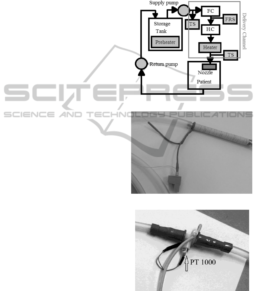
indicated in figure 1, where:
FC – represents the flow controller, used in
order to maintain a constant delivery flow of
the solution since the delivery flow varies
between 0.1 – 0.2 liters/minute;
HC – represents the individual heating
controller used in order to maintain the
temperature of the solution in the range of 41-
43˚C;
TS – represent temperature sensors that
measure the temperature of the solution at the
output of the preheating tank, and also the
temperature of the solution after the heating
element;
FRS – represents the flow rate sensors;
Storage tank – used in order to store and to
preheat the cytostatic solution at a temperature
of 38˚C;
Supply and return pump – ensure the
circulation of the solution from the storage tank
to the patient cavity, and back;
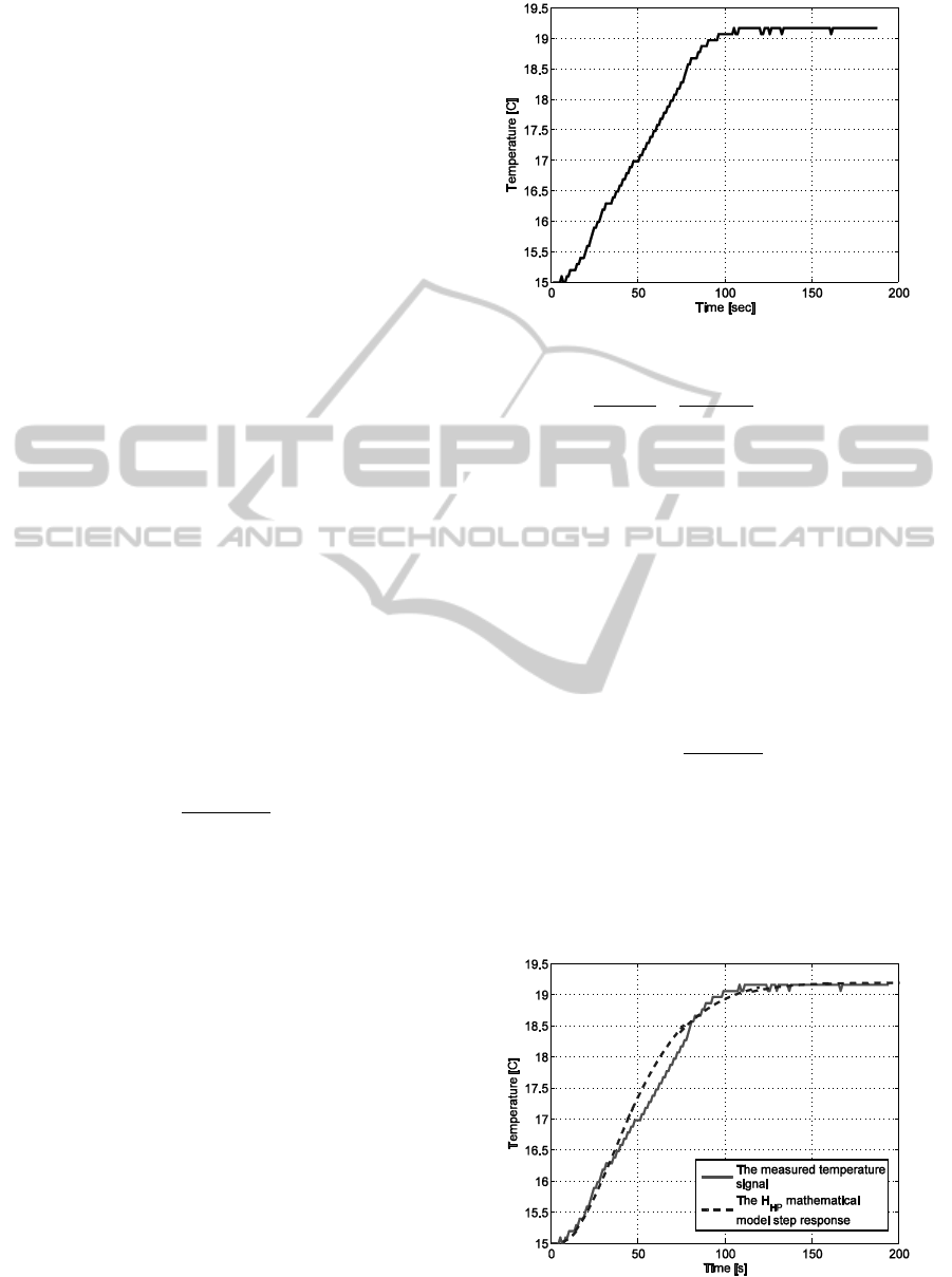
Individual heater – a heating resistance
constructed as windings on the exterior wall of a
cylindrical tube trough which the solution is
circulated (see figure 2), that works on the
principle of a heat exchanger;
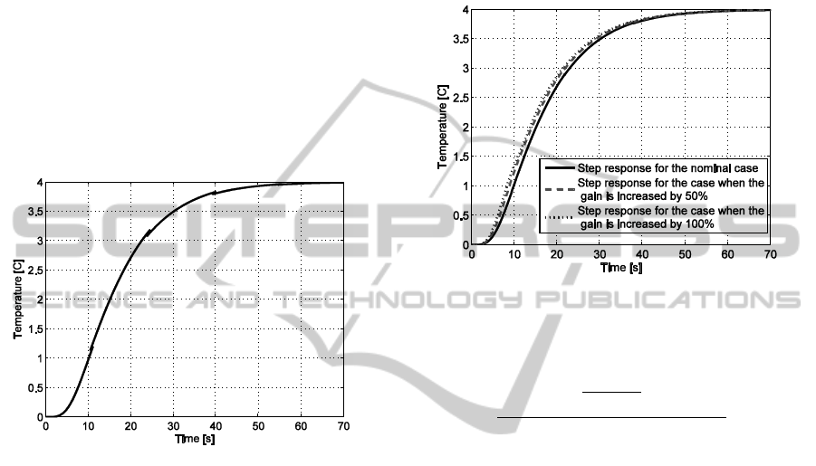
The temperature sensors used for the
implementation of the HIPEC equipment’s
temperature monitoring system are PT 1000, such a
sensor is presented in figure 3.
The equipment architecture presented in figure 1
contains only one delivery channel. On the final
HIPEC equipment the authors are going to use a
number of up to eight delivery channels that are
going to have the same individual elements
presented above. The number of channels was
chosen by the authors in terms of delivery and
optimal homogenization of the solution inside the
peritoneal cavity (Lungoci et al, 2014; Stroia et al,
2014).
In this paper the authors present the design of an
advanced automatic temperature control structure
capable of maintaining the required temperature for
the cytostatic solution.
Figure 1: The HIPEC equipment components.
Figure 2: The individual heater.
Figure 3: The PT 1000 temperature sensor.
The case where a H
∞
robust controller is used in
order to control the solution’s temperature is studied.
The robust control is selected since the heating
A Robust Temperature Controller Design for an Innovative Hyperthermic Intraperitoneal Chemotherapy Equipment
85
process model’s parameters depend on the cytostatic
solution’s flow rate.
2 MATHEMATICAL MODEL OF
THE HEATING PROCESS
2.1 The Transfer Function Model
The mathematical model of the heating process is
obtained by using a graphical fitting method on a set
of experimental data. The experimental data plotted
in figure 4 represents the solution’s temperature at
the output of the heating element, measured at a step
type input signal and at a constant solution flow of
0.1 litres/ minute. The heating process input signal is
represented by the electric power used to heat the
heating element. The step response for the heating
system was achieved by applying a constant electric
power of 15.5 watts to the heating element, without
the pre-heater associated to the storage tank. This
means that the initial temperature of the solution, for
the experimental data from figure 4, is the
temperature of 15˚C instead of 38˚C.
In order to obtain a transfer function model the
Strejc identification method was applied, on the
basis of the shape of the experimental data set. The
method was explained in detail in a related work
(Clitan, 2015). The identification method consists in
approximating the heating system through a transfer
function of the following form:
()
(1 )
HP
HP
n
HP
k
Hs
Ts
(1)
where n is the order of the process, k
HP
represents
the heating system gain, and T
HP
represents the
heating system time constant.
The order of the process and the heating system
time constant are obtained based on the correlation
between a series of calculated ratios and the Strejc
identification table (Mikleš and Fikar, 2007). The
corresponding ratios are calculated based on some
time periods determined graphically, in respect to a
tangent line drawn in the experimental signal’s
inflection point.
Following the identification method, a third
order transfer function with a time constant equal to
17 seconds results as the mathematical model for the
heating process.
The heating process gain (k
HP
) is determined
using the steady state temperature value (t
ss
) of
19.2˚C and the offset temperature value (t
o
) of 15˚C
(see figure 4).
Figure 4: The temperature experimental data.
19.2 15
0.271
15.5 0
ss o
HP
ss o
tt
k
uu
(2)
The value of the heating process gain will be the
same regardless of the temperature offset, since if
that value changes than the steady state temperature
value will also change accordingly, as long as a
constant solution flow rate and electric power is
supplied.
The heating process mathematical model is
obtained as the transfer function given below in (3).
The model validation is presented in figure 5 where
the simulated model’s step response is plotted in
respect to the experimental data set.
3
0.271
()
(1 17 )
HP
Hs
s
(3)
The heating process gain depends on the
solution’s flow value, since the output temperature
value varies with the flow. If the solution’s delivery
flow doubles in value (the maximum value of the
flow rate is 0.2 liters/minute) then the system gain
also doubles.
Figure 5: The heating process model validation.
ICINCO 2015 - 12th International Conference on Informatics in Control, Automation and Robotics
86

The control signal for the supplied electrical power
is applied using Pulse-width modulation (PWM).
The PWM transfer function has a gain equal to 30.
This gain needs to be added to the heating process
transfer function (H
HP
) and the resulted fixed part
transfer function (H
FP
) is given in (4).
3 3 2
30 0.271 8.13
()
(17 1) 4913 867 51 1
FP
Hs
s s s s
(4)
2.2 The State Space Representation of
the Model
The heating process fixed part model can also be
represented by using the state space representation
given in (5).
1 1 2
3
21
32
3
( ) 0.1765 ( ) 0.01038 ( )
0.0002035 ( ) ( )
( ) ( )
( ) ( )
( ) 0.001654 ( )
x t x t x t
x t v t
x t x t
x t x t
z t x t
(5)
where x
i
(t) represent the state variables, z(t)
represent the output temperature and v(t) represent
the input.
The state matrix, the input matrix, the output
matrix and the feedthrough matrix are presented
below in (6), (7), (8) and (9) correspondingly.
0.1765 0.01038 0.0002035
1 0 0
0 1 0
A
(6)
1
0
0
B
(7)
0 0 0.0061 0.271C
(8)
0D
(9)
3 ROBUST CONTROLLER
DESIGN
3.1 The H
∞
Robust Control
The main goal of a robust control is to design a
controller that stabilizes the process not only for its
nominal parameters values but also for the case in
which the parameters vary within a certain range
(Szelitzky et al, 2011). Such a control structure
ensures robust performance in response to parameter
uncertainty (Doyle et al, 1989). When using a robust
control structure the controlled process will have the
following requirements: low overshoot, short
settling time and disturbance rejection (Inoan, 2011).
Thus an H
∞
robust control is used for the
temperature control of the HIPEC equipment heating
process.
The H
∞
robust control design consists in finding
a controller that minimizes the lower linear
fractional transformation for the heating process
fixed part (Damen and Weinland, 2002).
In order to design an H
∞
robust controller the
augmented plant mathematical model (G) described
in (10) has to be constructed. This matrix form is
obtained from the state space representation which
includes the exogenous inputs and the error signals
(Inoan, 2011).
12
1 11 12
2 21 22
A B B
G C D D
C D D
(10)
3.2 The Robust Controller for the
Heating Process
The H
∞
controller design for the heating process
begins with the state-space representation of the
fixed part described in (5). Figure 6 shows the block
schematic representation of the fixed part state space
representation.
The heating process model’s parameters, namely
the process gain, depend on the cytostatic solution’s
flow rate since the heating process of the solution
depends on the amount and speed of the solution.
These values are set through the flow generated by
the supply pump.
As stated before the gain of the heating process
is influenced by the amount of solution flow. The
solution flow can vary between 0.1 – 0.2
liters/minute, thus the gain value can vary between
0.271 (considered to be the nominal value) and
0.542, which means that the parameters k
HP
varies
by +100%.
The parameter k
HP
may be represented as a lower
linear fractional transformation using the relative
variation
k
[0,1] and the matrix M
k
given in (11).
0
k
N
k
pk
N
M
(11)
were p
k
is the maximum relative uncertainty (in this
A Robust Temperature Controller Design for an Innovative Hyperthermic Intraperitoneal Chemotherapy Equipment
87

case equal to 1), and k
N
is the nominal value of the
heating process gain.
Figure 6: The block schematic representation of the fixed
part state space model.
Using the lower linear fractional transformation the
uncertain parameter block k
HP
from figure 6 is going
to be replaced with the group of blocks presented in
figure 7.
M
v
k
z
z
v
k
k
k
Figure 7: The heating process model validation.
The equations corresponding to the block
representation given in figure 7 are:
4
4
kN
k k N
z k v
z p v k v
(12)
were v
k
represents the exogenous input and z
k
represents the error signal.
The dynamic behaviour of the heating process
with the uncertain parameters is described by the
system equations given in (13).
1 1 2
3
21
32
3
3
( ) 0.1765 ( ) 0.01038 ( )
0.0002035 ( ) ( )
( ) ( )
( ) ( )
( ) 0.271 0.0061 ( )
( ) 0.001654 ( ) ( )
k
kk
x t x t x t
x t v t
x t x t
x t x t
z t x t
z t x t p v t
(13)
In order to obtain the augmented plant mathematical
model matrix form, the state space representation
from (13) must be written as (14), having one
exogenous input and one error signal.
1 k 2
k 1 11 k 12
2 21 k 22
x(t) Ax(t) B v (t) B v(t)
z (t) C x(t) D v (t) D v(t)
v(t) C x(t) D v (t) D v(t)
(14)
The matrix form of the augmented plant model is
presented in (15).
The robust controller is designed in order to
minimize the error signal using the command
hinfsyn from MATLAB
®
and the augmented plant
model given in (15) (Gu et al, 2005).
0.1765 0.01038 0.0002035 0 1
1 0 0 0 0
0 1 0 0 0
0 0 0.001654 0 0
0 0 0.001654 1 0
G
(15)
In order to ensure good transient response the
following weighting functions were added (Gu et al,
2005).
2
2
5 10
0.3
2 0.0001
p
u
ss
W
ss
W 0.02
(16)
The H
∞
robust controller’s transfer function is
obtained from the matrix form by using the formula
given in (17) (Ogata, 2009). The resulted
controller’s fifth order transfer function is presented
in (18).
1
( ) ( )
f
H s C sI A B
(17)
4 3 2
1 2 3 4 5
5 4 3 2
1 2 3 4 5
()
RC
n s n s n s n s n
Hs
s d s d s d s d s d
(18)
were
5
1
5
2
5
3
4
5
1
2
3
4
5
3.206 10
7.068 10
1.181 10
6814
132.3
1501
5211
5968
3081
0.154
n
n
n
n
n
d
d
d
d
d
(19)
+
0.0061 k =0.271
HP
z
x
v
1
x
1
x
2
=
x
2
x
3
=
x
3
v
4
-0.1765
-0.01038
-0.0002035
ICINCO 2015 - 12th International Conference on Informatics in Control, Automation and Robotics
88
4 SIMULATION RESULTS
The temperature control structure previously
designed is analyzed based on its simulated step
response using MATLAB
®
Simulink, since the
experimental results will be obtained for a
forthcoming paper. A negative feedback control
structure is implemented using the controller’s
transfer function given in equation (17) and the
transfer function given in (4) for the PWM actuator
and the heating process to be controlled.
The H
∞
robust control structure is first simulated
using the nominal value for the heating process gain.
The step response for the nominal case is presented
in figure 8.
Figure 8: The H
∞
robust controller’s step response for the
nominal case.
The cytostatic solution’s heating process is
simulated over the temperature of 38˚C (the
preheated solution’s value) thus in order to heat the
solution to a temperature of 42˚C a temperature
reference signal of 4˚C is used in simulation. On the
step input signal a second order delayed element of
15 seconds is used.
The overall performances for the nominal case
are: zero steady state error, no overshoot and a
settling time of 49 seconds. In figure 9, along with
the step response for the nominal case, the step
responses for the cases when the gain’s value is
increased by 50% and by 100% are also plotted.
It can be observed that no steady state error and
no overshoot are obtained even if the value of the
gain varies. The settling time when the heating
process gain is increased by 50% is equal to 48
seconds, and the settling time when the gain is
increased by 100% is 47.5 seconds.
The robust controller is compared with a PID
controller designed using the Strejc design method
(Clitan, 2015). A first order filter was added to the
PID controller in order to have a feasible controller
and the PID controller’s transfer function is given in
(20). The two controllers are compared based on
their step responses for the nominal case and the
case when the system’s gain varies by 50% or by
100%, those step responses are presented in figure
10.
Figure 9: The H
∞
robust controller’s step responses for the
heating process gain nominal value, the case when the
gain is increased by 50% and also by 100%.
1
0.2844 1 0.6486
41.933
0.006486 1
PID
s
s
H
s
(20)
From the analysis of figure 10 it results that the
performances generated by the robust controller are
much better than those obtained when using the PID
controller, designed using Strejc method. With the
PID controller an underdamped step response is
obtained having a high overshoot of 38% and a
settling time of 270 seconds, for the nominal case.
Even if we adjust the PID parameters so as to obtain
better performances, the step responses would still
change if the process parameters vary from the
nominal values.
Since the robust controller is faster and has no
overshoot, meaning that the solution is heated only
at the desired temperature, this control structure is
chosen as the most suitable one for the temperature
control of the developed HIPEC equipment.
In figure 11 the control signals generated by the
robust controller in order to obtain the step
responses presented in figure 9 are depicted. The
negative values for the control signals are not a
problem since in order to ensure the initial
conditions a default level of electric power is
ensured.
The robust control law is going to be
implemented on a microcontroller by computing the
A Robust Temperature Controller Design for an Innovative Hyperthermic Intraperitoneal Chemotherapy Equipment
89
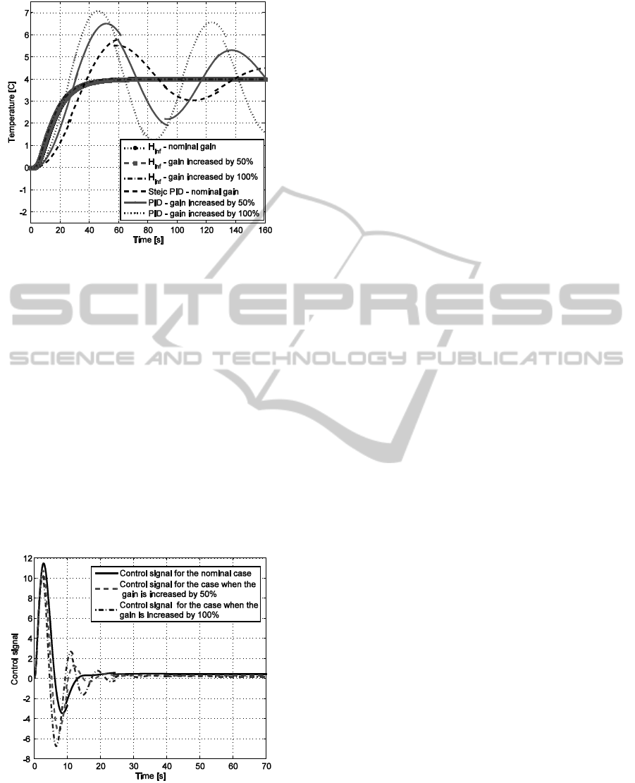
Figure 10: The graphical comparison between the H
∞
robust control structure and a PID control structure for the
nominal case and the case when the gain is increased by
50% and by 100%.
control signal according to the discrete-time
algorithm given below.
1 2 3
16 17
45
1 2 3
456
2.965 2.93 0.9653
2.22 10 5.551 10
0.1681 0.1681 1.319
1.301 0.1595 0.1595
k k k k
kk
k k k
k k k
c c c c
cc
e e e
e e e
(21)
where c
k
represents the current value of the control
signal that need to be computed, c
k-1
, c
k-2
, c
k-3
, c
k-4
, c
k-
5
represent past values of the control signal and e
k-1
,
e
k-2
, e
k-3
e
k-4
e
k-5
e
k-6
represent past values of the
temperature error signal.
Figure 11: The control signals generated by the robust
controller for the nominal case, for the case when the gain
varies by 50% and by 100%.
The advantage of using the designed robust
controller is that it stabilizes and generates suitable
performances for the heating process not just for the
nominal value of the heating process gain, but also
for the case in which the gain varies. The gain
variation is due to the solution’s flow rate and it was
shown that this control structure generates similar
overall performances even if a constant solution’
flow is not provided.
This means that by using a robust temperature
controller the flow control structure is no longer
necessary, thus reducing the cost of the HIPEC
equipment since up to eight individual flow control
structures would be eliminated.
5 CONCLUSIONS
The authors design in this paper a temperature
control structure for the cytostatic solution heating
process, so as to obtain affordable HIPEC
equipment. A disadvantage of commercially
available HIPEC equipments is their high cost and
the fact that they do not have advanced control
structures.
A robust control structure is selected since the
heating process model’s parameters depend on the
cytostatic solution’s flow rate, namely the heating
process gain. A H
∞
controller is designed using
MATLAB. From simulation it was deducted that the
robust control structure generates similar overall
performances for the nominal case, and also for the
case when the heating process gain varies by +50%
or by +100%. A zero steady state error, no overshoot
and a settling time of about 50 seconds are obtained
for the cytostatic solution heating process even if the
solution’s flow varies.
The robust control structure was compared with
a PID control structure, obtained using Strejc design
method. Unlike the robust control the PID control
generates worst performances even for the nominal
case, in which we have a constant flow of 0.1 liters/
minute.
The advantage of using the designed H
∞
robust
controller is that it reduces the number of controllers
needed on the HIPEC device. A flow control
structure is no longer necessary since it was shown
that the robust controller maintains the required
temperature even if the solution flow is not constant.
This means that flow rate sensors are also no longer
necessary.
By implementing the robust controller designed
in this paper the cost of the HIPEC equipment is
reduced since up to eight individual flow control
structures would be eliminated.
ICINCO 2015 - 12th International Conference on Informatics in Control, Automation and Robotics
90

ACKNOWLEDGEMENTS
The research activity that helped the authors to
elaborate the paper is sponsored by the research
projects no. 30104/2014 and no. 30141/2014,
financed by the Technical University of Cluj-
Napoca.
REFERENCES
Clitan, I., Muresan, V., Moga, D., Sita, V., Lungoci, C.,
July 2015. Measured signal identification and
temperature controller design for a HIPEC device. 38
th
International Conference on Telecommunications and
Signal Processing TSP, Prague, Chech Repuplic, in
press.
Damen, A., Weinland, S., 2002. Robust control.
Eindhoven University of Technology. Eindhoven,
Chapter 7.
Doyle, J., Glover, K., Khargonekar, P., Francis, B., 1989.
State-space solutions to standard H-2 and H-infinity
control problems, IEEE Trans. Auto. Control 34 (8),
pp. 831-847.
Gleben, O., Gilly, F. N., Arvieus, C., Cotte, E., Boutitie,
F., Mansvelt, B., Bereder, J. M., Lorimier, G.,
Quenet, F., Elias, D., 2010. Peritoneal carcinomatosis
from gastric cancer: A multi-institutional study of 159
patients treated by cytoreductive surgery combined
with perioperative intraperitoneal chemotherapy,
Annals of Surgical Oncology 17, pp. 2370-2377.
Gu, D. W., Petrov, P. H., Konstantinov, M. M., 2005.
Robust control design with Matlab, Springer-verlag.
London, Chapters 4 and 8.
Inoan, I. , Abrudean, M. , Szelitzky, T., 2011. Robust H
∞
position control of an unloading machine from a rotary
hearth furnace, Scientific bulletin of the Petru Maior
University of Târgu Mureș, 8 (2), Petru Maior
University Publisher, Targu Mures, pp. 38-43.
Koppe, M. J., Boerman, O. C., Oyen, W. J. G., Bleichrodt,
R. P., 2006. Peritoneal carcinomatosis of colorectal
origin - Incidence and current treatment strategies,
Annals of Surgery 242 (2), pp. 212-222.
Levine, E. A., Blazer, D. G., Kim, M. K., Shen, P.,
Stewart, J. H., Guy, C., Hsu, D. S., 2012. Gene
expression profiling of peritoneal metastases from
appendiceal and colon cancer demonstrates unique
biologic signatures and predicts patient outcomes,
Journal of the American College of Surgeons, 214 (4),
pp. 599 – 606.
Lungoci, C., Raus, I., Oniu, T., Moga, D., Stroia, N.,
Muntean, V., Petreus, D., Mironiuc, I. A., 2014.
Assessment of temperature distribution in
intraperitoneal chemohyperthermia, International
Conference on Advancements of Medicine and Health
Care through Technology, IFMBE Proceeding, 44, pp.
193–196, Cluj-Napoca.
Mikleš, D. J., Fikar, M., 2007. Process modelling,
identification, and control, Springer. Verlag Berlin
Heidelberg, Chapter 6 and 7.
Ogata, K., 2009. Modern control engineering, Prentice
Hall. New Jersey, 5
th
edition.
Spratt, J. S., Adcock, R. A., Muskovin, M., Sherrill, W.,
Mckeown, J., 1980. Clinical delivery system for
intraperitoneal hyperthermic chemotherapy, Cancer
Research, 40 (2), pp. 256–260.
Stroia, N., Moga, D., Lungoci, C., Moga, R., and Petreus,
D., 2014. Development of a hyperthermic intra-
peritoneal chemotherapy equipment architecture based
on the cyber-physical system paradigm, Third
International Workshop on Cyber Physical Systems.
Bucuresti.
Sugarbaker, P. H., 2005. Technical handbook for the
integration of cytoreductive surgery and perioperative
intraperitoneal chemotherapy into the surgical
management of gastrointestinal and gynecologic
malignancy, The Ludann Company Grand Rapids,
Michigan, 4
th
edition.
Sugarbaker, P. H., Clarke, L., 2006. The approval process
for hyperthermic intraoperative intraperitoneal
chemotherapy, European Journal of Surgical
Oncology, 32 (6), pp. 637-643.
Sugarbaker, P. H., 2012, Cytoreductive surgery plus
hyperthermic perioperative chemotherapy for selected
patients with peritoneal metastases from colorectal
cancer: a new standard of care or an experimental
approach?, Gastroenterology Research and Practice,
2012 ID:309417, 9 pages.
Szelitzky, T., Inoan, I., Dumitrache, D. C., 2011.
Advantages of robust control for series load frequency
controlled induction heating inverters, Journal of
Control Engineering and Applied Informatics, 13 (1),
pp. 62-68.
A Robust Temperature Controller Design for an Innovative Hyperthermic Intraperitoneal Chemotherapy Equipment
91
