
Three-Layered Software Architecture and Its Variability
for Teleoperated System
Yasuharu Kunii, Yoshiki Matsui and Masaru Furukawa
Human Machine System Laboratory, Chuo University, Bunkyo-ku, Tokyo, Japan
Keywords: System Architecture, Teleoperation.
Abstract: In a teleoperated system, robots are often required to easily change among various modes of operation;
further, an efficient development of large-scale teleoperated systems is desired. Thus, we propose a three-
layer software architecture implemented using a database node module (DNM). All modules are connected
to a DNM, with connections among modules defined as virtual connections. It is possible to change
connections during operation via the virtual connection of the DNM, and the DNM can achieve high-speed
communication and high-speed connection changes. We examined the evaluation index of our module
design using this architecture because module interface and function design influence the architecture.
Finally, we confirmed that a robot based on our architecture worked in a real environment.
1 INTRODUCTION
Remote mobile robots often work in extreme
environments such as planetary surfaces, disaster
sites, and other dangerous zones. In general, they are
required to achieve a stable performance during
advanced missions in these environments. Several
system architectures for robots have been proposed
for achieving such capabilities (Ahn et al., 2010;
Medvidovic et al., 2011; Volpe et al., 2001).
Teleoperators comprise several functions such as
action planning, recognition, and motion control and
various subsystems such as moving mechanisms, a
communication system, and various sensors.
Because these systems are multifunctional, they
often become bulky and complex. Conversely, these
systems are required to be scalable and efficiently
adapt to any situation. Thus, their control and
operating software must enable users to freely
combine installed elements via a network and
modify system components.
To flexibly respond to environmental changes or
unpredictable problems, it is necessary to change the
system configuration or add new functions from a
remote site over a network. Most conventional
software architectures for teleoperation cannot
operate a robot if a failure occurs at a remote site
(Estlin et al., 2008; Baranyi, 2011; Hoshino and
Kunii, 2012; Galambos, 2012). This arises because
of difficulties in the dynamic modification of robotic
functions. From this viewpoint, an architecture with
advanced scalability and variability is required for a
mission-critical operation.
Teleoperated systems must also address info-
communication, i.e., the transmission of sensory
information from a remote site to a human operator.
For the safe operation of a robot, information of
system conditions should be known; however, the
complexity of the system makes it difficult to
understand its various states. To overcome these
limitations, we propose a system architecture that
emphasizes variability in the structure of functions
and data transparency (Ando et al., 2011).
In short, we need a fault-tolerant robot system. In
widely used robot middleware such as R.O.S. and
RT-Middleware targeted at easily implementing
robot systems, adapting teleoperated systems is
especially important. Therefore, we propose our
architecture for a fault-tolerant system in which the
ease of implementation is crucial. Accordingly, our
architecture was constructed using RT-Middleware.
In this study, we discuss the importance of a
module design and the granularity of the module in
our three-layer architecture. Moreover, we show the
evaluation index of the module design and confirm
the validity of our architecture via experimentation.
349
Kunii Y., Matsui Y. and Furukawa M..
Three-Layered Software Architecture and Its Variability for Teleoperated System.
DOI: 10.5220/0005547703490356
In Proceedings of the 12th International Conference on Informatics in Control, Automation and Robotics (ICINCO-2015), pages 349-356
ISBN: 978-989-758-123-6
Copyright
c
2015 SCITEPRESS (Science and Technology Publications, Lda.)
2 PROPOSED SOFTWARE
ARCHITECTURE FOR
TELEOPERATED SYSTEMS
In general, teleoperators operate at locations that are
not amenable to human activity. Moreover, the
environment of these locations may not be well
known. Therefore, system failures may occur
because of the nonconformity of parameters or
algorithms. Further, harsh environmental conditions
often cause hardware problems. In such cases, the
system should be alterable by software alone without
physical restriction, i.e., the system should be
flexible and adapt the structure of its functions to
suit a situation. Moreover, as mentioned above, the
safe operation of the robot requires knowledge of the
state of the system during its operation.
Therefore, we designed a system that emphasizes
flexibility and variability in its structure of functions
and transparency and accessibility of data. In our
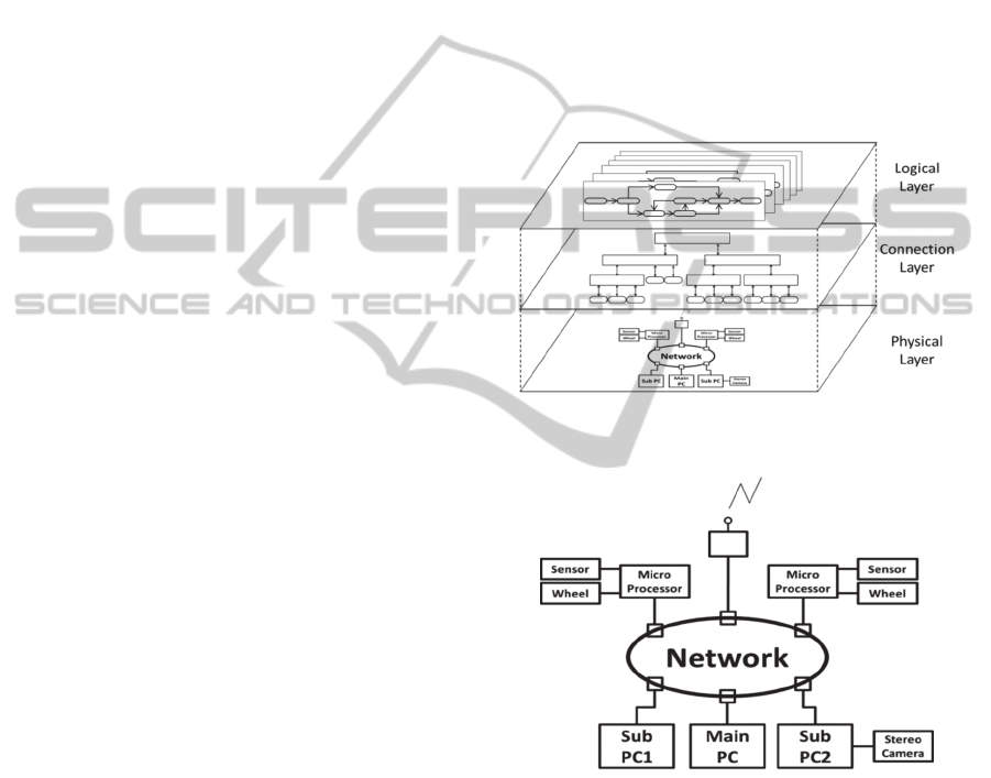
proposed architecture, which is illustrated in Figure
1, each function is modularized and connected via a
network. Advanced variability is achieved by
defining real and virtual connections within different
layers. Each layer of the architecture is detailed in
the subsections as follows.
2.1 Physical Layer
In the bottom layer, all hardware is connected via a
network, as shown in Figure 2. Any function can be
directly accessed and connections can be changed
using software, which imposes no physical
restrictions. Thus, our system is accessible and has
an advanced variable structure. In addition, it
increases fault tolerance by minimizing lost units in
the event of system failures.
2.2 Connection Layer
A robot operating in remote locations must be able
to switch among multiple tasks, each task
comprising a module’s behavior logic, in response to
a given situation; however, connection switching is
very expensive to realize in practice. Thus, the
middle layer of our proposed architecture manages
the actual modules of the system and virtually
realizes task dependencies defined at the top layer.
This is performed by the database node module
(DNM), which relays information among the
functions of modules. In particular, all modules are
connected to the DNM, as shown in Figure 3, and
data are exchanged at a high speed via shared
memory. The DNM transmits destination addresses
of each module containing task dependencies
defined by a user in a logical layer. In this manner,
the DNM realizes a network list. Hence, module
connections can be switched by changing reference
pointers, while the DNM manages the timing of the
switches.
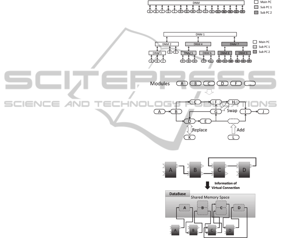
Moreover, because the DNM contains the data of
all modules, it realizes high system transparency. To
achieve load balancing and reduced traffic, the
DNM can be arranged in a hierarchical structure,
illustrated in Figure 4. Further, because the
hierarchical structure limits the range of failures, this
structure enables an easy identification of the causes
of failures.
Figure 1: Conceptual diagram of our three-layered
architecture.
Figure 2: All hardware is connected via a network.
2.3 Logical Layer
The top layer enables users to intuitively compose
tasks, thereby improving the efficiency of task
development. Users can collect the necessary
modules and connect them according to the intended
task flow, as shown in Figure 5. Our method allows
free swapping, addition, replacement, and deletion
of modules. Thus, the system can effectively
reconstruct its functions and respond quickly to
changing situations or any problems encountered.
ICINCO2015-12thInternationalConferenceonInformaticsinControl,AutomationandRobotics
350
3 DATABASE NODE MODULE
The efficiency of development and operation
processes is enhanced in our proposed architecture
by function modularization. By modularizing every
function, the development process can be shared and
both development and maintenance can be quick.
Moreover, the development process becomes more
efficient because a once-developed function is
essentially a software resource that can be diverted
to other systems.
To execute task flows designed by an operator
on the logical layer, task connections of the flows
have to be converted to virtual connections of
software modules. These virtual connections are
controlled and managed by the DNM.
3.1 Task Flow by Virtual Connection
When executing logic constructed on the logical
layer, the DNM reads the netlist of the virtual
connection, delivers the data to each functional
module, and controls its behavior. To construct more
flexible logic into the logical layer, we introduce a
port same as that adopted in RT-middleware. To
establish a virtual port connection, the DNM
generates shared-memory space corresponding to the
number of ports in each module and executes data
communication.
Moreover, when a task module straddles two or
more DNMs, intermodule data communication
requires the synchronization of the memory space
among databases. While realizing this
synchronization, a user-designed idea should not be
input into the connection layer. Therefore, the DNM
reads the netlist and automatically constructs data
routing among databases based on real connections,
as shown in Figure 6. The overall flow is as follows:
1) Data searches the position of an addressee
module.
2) The course from a transmitting agency module to
an addressee module is established.
3) The database of an addressee generates the
memory space for transmitting agency modules.
4) Memory space is synchronized among databases,
and data communication is performed.
By virtual connections using the DNM, a task can be
switched dynamically and at high speeds. In a
conventional system in which modules are directly
connected during task switching, the modular
connection is reconnected by a single separation re-
degree. Because task switching merely involves
replacing the virtual connection information read
into the DNM, modules can be switched at a reduced
cost. When a hardware component breaks down, the
system can shift to the backup node at a high speed
by rewriting the virtual connection. This is an
important stabilizing feature that is advantageous to
manipulate a robot in remote places where direct
maintenance is impossible.
Figure 3: Module connections with the DNM.
Figure 4: Hierarchical structure of the DNM and modules.
Figure 5: Changing the initial task flow.
Figure 6: Analysis of virtual connections on the DNM.
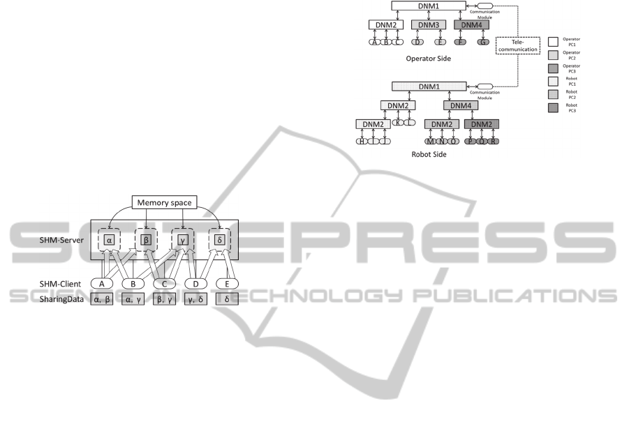
3.2 Data Communication among
Modules using Shared Memory
The function Shared-Memory (SHM) Server
supplied to a database enables data communication
among modules. Data communication is executed
when the SHM Server creates a shared-memory
space according to demand from the SHM Client
(functional modules), which then accesses data in
the space, as illustrated in Figure 7. When a
functional module wants to access data, it displays a
Three-LayeredSoftwareArchitectureandItsVariabilityforTeleoperatedSystem
351
pointer to the storage address of the data. In this
manner, data are exchanged at higher speeds than
possible using typical middleware. Moreover,
although shared memory is generally implemented
using a single CPU, two or more memory spaces are
synchronized using the Common Object Request
Broker Architecture network, enabling the DNM to
share data among two or more CPUs. Therefore,
modular data access can be distributed, and high
system performance can be maintained.
Further, the SHM Server offers a semaphore that
secures data consistency. Using the semaphore, data
can be safely exchanged within shared memory by
an exclusive control of data access to the shared-
memory space.
Figure 7: Shared memory system for task flow.
3.3 Realization of Remote Control and
Task Management using Our
Three-Layer Architecture
The system controls a multitasking robot from a
remote location; this requires the implementation of
our Three-Layered Architecture on both operator
and robot sides and their connection via a
communication module, as shown in Figure 8. Thus,
the two separate systems are incorporated into one
large system. By constructing a separate tree for
each side, the mutual system ensures a more stable
communication path and robustness for severe
environments. Each communication module is
equipped with a data transceiver function among
systems, a modular controlling function, and a task
controlling function using TCP.
A user selects a required module, creates various
tasks, and assigns duties via flexible exchange from
an operator side. Examples of user-defined tasks
include combined mapping, course planning, driving
the wheels of remote investigation vehicles, and
operating a camera and a manipulator during remote
sampling.
4 MODULE DESIGN
Our architecture is regarded as having high
variability. To improve the variability of the system,
the connections among modules should be able to be
easily changed.
Figure 8: DNM structure in a tele-navigation system.
4.1 Structural Variability
To increase structural variability, module
connections should be able to be easily changed. Our
architecture cannot connect modules that have
different interfaces. Developers can define interfaces
when creating a module; further, modules can have
multiple interfaces. A module that has many
different interfaces is difficult to connect. When the
number of interfaces of a module is reduced,
structural variability improves. The interface shows
the relation among modules.
4.2 Module Function
Functions that include a module should have a deep
relation with one another. Because modules consist
of their functions, they are not allowed to contain
unrelated functions. To support structural variability,
a module should be divided into smaller
components. Choices of the structure increase if
there are many small modules. In other words,
variability can be improved.
4.3 Evaluation of Module Design
It is possible to evaluate the architecture to
determine whether it has high variability (as
described later); however, implementation modules
are different from modules created for evaluation.
Modules created for evaluation consider variability,
but modules in actual operation may not consider
variability. Because module design for actual
operation depends on developers, it is necessary to
evaluate the design. A module is quantitatively
evaluated to eliminate the differences in variability
based on creators. At the same time, we evaluate
whether the module is suitable for our architecture.
ICINCO2015-12thInternationalConferenceonInformaticsinControl,AutomationandRobotics
352

In general, a module design of large-scale
systems has been discussed in the literature (E.
Yourdon et al., 1979). It is clear that the design of
each module has a large influence on a system. A
general architecture has strict regulations regarding
module design. In such cases, a module is evaluated
according to the design regulations. However, in our
three-layer architecture, there are no regulations
governing module design. Instead, module design
guidelines exist. We need a method to estimate
whether a given module deviates from these
guidelines. The evaluation of module design of our
three-layer architecture is different from that of
general architectures.
4.4 Evaluation Index of Modules
Module design and its interface are important in
terms of changing module connections while a robot
is operating. It is necessary to estimate whether the
module is of a good design; this is the heart of
evaluating module design. Therefore, evaluation is
estimated first using the number of lines of the
module source code itself. The subsections given
below summarize a number of different indexes we
used for our evaluation.
4.4.1 Degree of Relation
This index shows the strength of the relation of a
module and other modules. The number of lines
used for communication among modules and the
number of lines of an entire module are compared as
follows:
∑
∈
.
(1)
Here, S is a set of programs for communication,
St(S) is the number of lines for the communication
of module x, and M(x) is the total number of lines of
module x. A module should be designed that the
relationship between modules is low. When one
constructs a module with a good design, the related
degree described here is low.
4.4.2 Degree of Concentration
This index shows the strength of the relation among
the functions of a module. Modules are evaluated by
the total percentage of the number of lines of a
related function (Okamoto et al., 2012) as follows:
∑∑
1,
2
∙
1
∙
2
∈∈
.
(2)
Here, F is a set of all functions in modules, Re(f1,f2)
defines the relation of function f1 and f2, which a
modules should be composed of high relationship
function. The degree of concentration becomes high
with good designs.
4.5 Module Design Experimentation
We evaluated a module of a traveling system in
which three modules exist. We calculated the degree
of relation and the degree of concentration of these
modules, and then, we made alterations on the basis
of these calculations. We revalued each module after
such change and argue variability of the entire
system.
4.5.1 Evaluation using the Suggestion Index
We calculated the suggestion index using three
modules (results shown in Table 1). Reviewing the
degree of concentration for module A, it was the
lowest value (less than 50%) as compared with other
modules. Such a module appears to be a bad design;
thus, it was redesigned. The related degree of
module B was also evaluated and was observed to
have the highest value (more than 70%) as compared
with other modules. Therefore, this module was also
redesigned.
4.5.2 Redesign of Modules
Module A was the module that revises the distortion
of the run course. A different calculation system was
included in one module. The degree of concentration
was the low value because different calculation
method exists in single modules. This module
divided every calculation system because a relation
was the low function, which is illustrated in Figure 9.
Next, module B makes a run order with handed
data. The same type of data is received at the same
time. It was designed so that it might be used
exclusively. The degree of relation was the high
value because it was the module from which much
data was received. A data conversion module was
recreated because the same data connected to this
module was set to one, as shown in Figure 10.
4.5.3 Evaluation after Design Changes
Table 2 shows the calculated suggestion index
values after redesign. Both the degree of relation and
the degree of concentration are better. When
changing a module, a programmer is conscious of an
index because an index uses the number of lines of a
given program.
This change will benefit this architecture. While
a robot operates, connections between the modules
Three-LayeredSoftwareArchitectureandItsVariabilityforTeleoperatedSystem
353
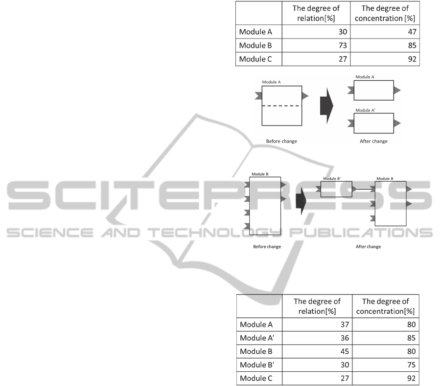
can be easily changed. Note that another benefit is
that the module does not depend on data interface.
5 EXPERIMENTATION
5.1 Simulation Results
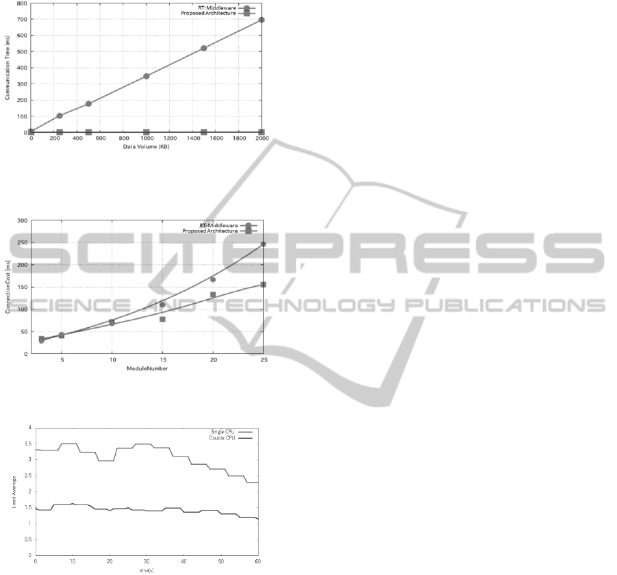
5.1.1 Data Communication Time
To evaluate the performance of our system, we
compared data communication time of our virtual
intermodule connections with that of conventional
RT-Middleware. Results of this comparison are
shown in Figure 11. As shown in the figure, the
communication time of the virtual connections in
our architecture was lower than that of conventional
RT-Middleware. Therefore, we conclude that data
communication in this system is efficient.
5.1.2 Variability
To compare variability, we measured the task-
switching speed of actual connections using RT-
Middleware and that of the virtual connections in
our proposed architecture. Results of the comparison
are shown in Figure 12. The switching speed of our
architecture was faster than that obtained from RT-
Middleware. Therefore, we confirm that our
architecture offers efficient operation and task
execution.
5.1.3 Load Distribution
We investigated how the load applied to a system
would change when all modules are connected to a
single DNM and when a module is distributed
through two DNMs, each assigned to a separate PC.
The load average as a function of time for the two
cases is shown in Figure 13. As shown in the figure,
we observe that adopting the multi-CPU
configuration reduces system load relative to
connecting all modules to a single DNM.
5.2 Implementation Experiment
The robot system adopted in the implementation
experiment was Beetle-One, shown in Figure 14.
Beetle-One is a test prototype for the planetary
exploration Rover Micro6. An electric wheelchair,
designed in the same manner as the Rover, was used
as the test system. A joystick and computer control
was made compatible with the two-wheel
differential-steering system adopted in both systems.
Table 1: Evaluation using the suggestion index.
Figure 9: Module division.
Figure 10: Creating a new module.
Table 2: Evaluation after design changes.
Figures 15–18 show an implemented system
using our proposed architecture. Three distinct tasks
were assigned to the half-autonomous travel system
Beetle-One; each task was governed by the
corresponding operator side task. Figure 15(a) shows
the navigation system task in which a user specifies
a target location, and then, the system automatically
generates the run course of Beetle-One and directs it
safely to the target.
Another task is assigned to the GUI modules
mediated by a user on an operator side. Figure 15(b)
shows a visual odometry landmark tracker system
task; this task acquires geographical feature data for
the navigation system or visual odometry (i.e., the
run orbit of Beetle-One) using the stereo camera on
board of Beetle-One. It is run by the module group
that acquires the azimuth difference picture from a
stereo camera, the GUI display, and the operation
ICINCO2015-12thInternationalConferenceonInformaticsinControl,AutomationandRobotics
354
module group that calculates the details and
generates visual odometry.
Figure 11: Comparing communication times in a system
with 10 modules for our proposed architecture and RT-
Middleware.
Figure 12: Switching time of module connections for our
proposed architecture and RT-Middleware.
Figure 13: Load averages for single and double CPU
experiments.
Figure 16(a) shows the map system task; this
task creates a map using the Laser Range Finder
(LRF) carried on Beetle-One. The task is run by a
module group that acquires instructional data for the
pan–tilt mechanism, the LRF, and an operation
module group that collates the latest and
accumulated data to generate the map.
A half-autonomous run of Beetle-One is realized
by assigning these tasks in combination. In this
system, task switching and multitasking are
managed by an operation GUI for system
management. The navigation system and visual
odometry landmark tracker system interlock,
whereas the map system operates independently.
Moreover, these tasks are virtually connected by the
logical layer in our Three-Layered Architecture. The
actual connection with the DNM in the connection
layer is shown in Figure 16(b).
A network assigns two PCs and the
microcomputers of Beetle-One to the same LAN via
a cable LAN, and each module is assigned to a
separate PC. Programmed with the above tasks, the
robot was directed to run the enclosure of a
university. The experimental situation is shown in
Figure 17. This experiment tests the performance of
orbit compensation and the landmark tracking
system, as well as whether the system is operating
normally from both sides of arithmetic processing,
such as picture acquisition from the camera, visual
odometry generation, course planning, DEM data
access, and processing to the GUI. Clearly, from this
experiment, the DNM of our proposed architecture
ensures normal data communication and task flow
and demonstrates the capacity to operate a robot.
The final run locus and terrain evaluation map are
shown in Figure 18. The system operated
successfully for a long time, with proven stability
and disaster tolerance.
The DNM was implemented on our test-bed
rover and evaluated by operating experiments.
Functions and stability of the architecture with the
DNM were confirmed by successful long-distance
traversal of the rover. As mentioned above, we
showed that our proposed architecture can improve
the efficiency in the development and operation
stages of a teleoperated system.
6 CONCLUSIONS
In this paper, we proposed a system architecture for
teleoperators that offers advanced flexibility and
variability, efficiency, scalability, and transparency.
We realized advanced variability by defining real
and virtual connections in different layers. Software
modules are managed by the DNM. Further, system
transparency is improved because the DNM contains
the data of all modules. We validated our
architecture characteristics via simulation. Thus, our
proposed architecture provides significant
contributions to the development and operation of
teleoperators. In future work, we plan to further
improve the efficiency of our proposed architecture
by incorporating a task scheduler into the logical
layer.
Three-LayeredSoftwareArchitectureandItsVariabilityforTeleoperatedSystem
355
Figure 14: Beetle-One (left) and Micro6 Rover (right).
Figure 15: (a) Navigation system task (left); and (b) image
processing system task (right).
Figure 16: (a) Map system task (left); and (b) Connection
Layer (right).
Figure 17: System implementation.
Figure 18: Run locus and terrain evaluation map.
ACKNOWLEDGEMENTS
This research is supported by a joint research project
in the Institute of Science and Engineering of Chuo
University, Japan.
REFERENCES
Ahn H., Lee D., Ahn S., 2010. A hierarchical fault tolerant
architecture for component-based service robots, Proc.
of Int’l Conf. on INDIN, pp. 487-492.
Ando N., Kurihara S., Biggs G., Sakamoto T., Nakamoto
H., Kotoku T., 2011. Software deployment
infrastructure for component based RT-systems,
Journal of Robotics and Mechatronics, Vol. 23, No. 3
pp. 350-359 .
Baranyi P., 2011. Vibrotactile force feedback for
telemanipulation: Concept and applications, Proc. of
Int’l Conf. on ConInfoCom, pp. 1-6.
Estlin T., Castano R., Gaines D., Bornstein B., Judd M.,
Anderson R. C., Nesnas I., 2008. Supporting increased
autonomy for a Mars Rover, Proc. Int’l SAIRAS.
Galambos P., 2012. Vibrotactile Feedback for Haptics and
Telemanipulation: Survey, Concept and Experiment, J.
Appl. Sci., Vol. 9, No. 1, pp. 41-65.
Hoshino K., Kunii Y., 2012. Three-Layered Architecture
for Tele-operator and Its System Test, Robot
Intelligence Technology and Applications 2012
Advances in Intelligent Systems and Computing, Vol.
208, pp. 105-114.
Medvidovic N., Tajalli H., Garcia J., Krka I., Brun Y.,
Edwards G., 2011. Engineering heterogeneous
robotics systems: a software architecture-based
approach, Computer, Vol. 44, pp. 62-71.
Okamoto W., Kameda K., Yamashita T., Sunata T., 2012.
Software Diagnosis Technique to Evaluate and
Improve its Maintainability, Forum on Information
Technology, Vol. 11, No. 1 pp. 253-256.
Volpe R., Nesnas I., Estlin T., Mutz D., Petras R., Das H.,
2001. The CLARAty architecture for robotics
autonomy, Proc. IEEE Aerospace Conf., pp. 121-132.
E. Yourdon and L. Constantine, 1979. Structured Design:
Fundamentals of a Discipline of Computer
Programming and Design, Prentice Hall.
ICINCO2015-12thInternationalConferenceonInformaticsinControl,AutomationandRobotics
356
