
Continuous Pre-Calculation of Human Tracking with Time-delayed
Ground-truth
A Hybrid Approach to Minimizing Tracking Latency by Combination of Different
3D Cameras
Philip Nicolai, Jörg Raczkowsky and Heinz Wörn
Institute for Anthropomatics and Robotics (IAR) - Intelligent Process Control and Robotics Lab (IPR),
Karlsruhe Institute of Technology (KIT), Engler-Bunte-Ring 8, Karlsruhe, Germany
Keywords: 3D Camera, Tracking, Data Fusion, Probability Propagation.
Abstract: We present an approach to track a point cloud with a 3D camera system with low latency and/or high frame
rate, based on ground truth provided by a second 3D camera system with higher latency and/or lower frame
rate. In particular, we employ human tracking based on Kinect cameras and combine it with higher frame-
rate/lower latency of Time-of-Flight (ToF) cameras. We present the system setup, methods used and
evaluation results showing a very high accuracy in combination with a latency reduction of up to factor 30.
1 INTRODUCTION
The interaction of humans and robots in a shared
workspace is an ongoing field of research.
Applications cover a wide field from domains where
robotic technologies have been traditionally
employed, e.g. industrial scenarios, to relatively new
fields such as surgical applications. In all domains,
the safety of the human interacting with the robotic
system is paramount. For appropriate safety
considerations as well as for many applications in
human-robot interaction, humans in the environment
have to be perceived, e.g. detected and located in 3D
space. Both the latency of the perception system and
the frame rate heavily influence the possible
application scenarios, especially for safety critical
applications.
This paper presents an approach for combining a
fast 3D camera, i.e. with low latency and/or high
frame rate, with a secondary, slower 3D camera that
provides human tracking as a ground truth. The
faster camera pre-calculates the full-body human
point cloud in real time. To achieve this, the time-
delayed ground truth of the slower camera is
propagated forward in the data stream of the faster
camera using 2D optical flow and then refined to
segment the full human point cloud from the scene.
Segmentation is performed by calculating connected
regions, rejecting outliers based on a simple tracking
model and applying background subtraction. This
results in a highly accurate tracking estimation in
time with the faster camera, based on the time-
delayed ground truth of the secondary system.
While the approach is implemented and
evaluated using human tracking by a 3D camera as
ground truth, the algorithm is not tailored to human
tracking (either implicitely or explicitly). On the
contrary, it is designed with the goal to be adaptable
to other applications (different combinations of
tracking tasks and modalities), e.g. using a thermal
imaging camera as delayed ground truth for 3D
tracking of objects with specific temperatures.
The developed algorithm is applied to two
different scenarios for tracking a human body as a
point cloud in 3D space: a) low-latency tracking
based on ground truth with a latency of one to
several seconds, b) high frame rate tracking based on
ground truth with a lower frame rate.
Optical flow and depth information have been
used in various works for segmenting and tracking
humans and objects. Examples are (Okada, 2000),
where depth and optical flow were used to estimate
the 3D position and motion of a person; using
optical flow to track persons between multiple
cameras to avoid occlusions (Tsutsui, 2001) or
applying optical flow and depth cues to vehicle-
based moving object segmentation (Klappstein,
2009). The combination of 2D and 3D Kinect data
121
Nicolai P., Raczkowsky J. and Wörn H..
Continuous Pre-Calculation of Human Tracking with Time-delayed Ground-truth - A Hybrid Approach to Minimizing Tracking Latency by Combination of
Different 3D Cameras.
DOI: 10.5220/0005548901210130
In Proceedings of the 12th International Conference on Informatics in Control, Automation and Robotics (ICINCO-2015), pages 121-130
ISBN: 978-989-758-123-6
Copyright
c
2015 SCITEPRESS (Science and Technology Publications, Lda.)
has been researched e.g. in (Jóźków, 2014) with the
purpose of mobile mapping in indoor environments.
However, the combination of different 3D
cameras with 2D/3D propagation of tracking
probabilities has not been investigated before.
2 SYSTEM SETUP
The Robot Operating System has been used as a
communication framework (Quigley, 2009). It is
based on sending time-stamped messages on named
topics and provides transport mechanisms for both
2D and 3D image data.
Processing of data acquired by the different 3D
cameras has been performed using OpenCV
(Bradski, 2000) for 2D images and Point Cloud
Library (Rusu, 2011) for 3D data.
In the following, we give a short description of
the scenarios and camera systems to which the
algorithm has been applied.
2.1 Latency Minimization Scenario
The first scenario is based on the sensing system of
OP:Sense, a research platform for surgical robotics
(Moennich, 2011). Four RGB-D Microsoft Kinect
cameras (first generation), featuring a resolution of
640 x 480 pixel for both depth and color image at 30
frames per second (fps), supervise a narrow scene
from different points of view. Human tracking and
fusion is performed based on the OpenNI tracking
libraries (Beyl, 2013). Due to the distributed setup of
the system, the Kinect system features a latency of
about 950 ms.
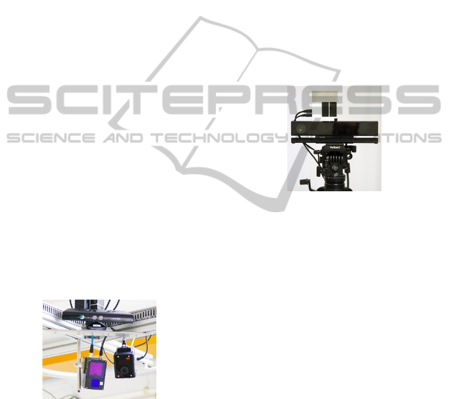
Figure 1: Sensor node with Kinect (top), ToF camera
(bottom center); the optical tracking (bottom right) was
not used for this work.
A secondary camera system consists of six Time
of Flight (ToF) pmd[vision] S3 cameras. With a
resolution of 64 x 48 pixels, they provide depth
sensing (e.g. point clouds and depth image) as well
as an amplitude image that contains the signal
strength of the measurement. Figure 1 shows one
sensor node with both Kinect and ToF camera.
2.2 Frame Rate Optimization Scenario
In this scenario, a RGB-D Microsoft Kinect II has
been used for human tracking. The camera provides
a color stream with 1920 x 1080 pixels and a depth
data stream with 512 x 424 pixels, both at 30 fps.
Human tracking was performed using the Microsoft
Kinect SDK 2.0 on a Windows system and
streaming to ROS has been realized using a custom
bridge based on the win_ros stack.
A Bluetechnix Argos 3D P100 ToF camera with
a resolution of 160 x 120 pixels provides depth data
and an amplitude image, both at a rate of up to 160
fps. Figure 2 shows the demonstration setup.
Figure 2: Argos P100 3D mounted on top of Kinect II.
3 METHODS
For easier reading and consistency with the
scenarios and evaluation, we designate the source of
the ground truth in the following as “Kinect camera”
and the secondary camera as “ToF camera”.
However, the presented algorithm is naturally
applicable to a wide range of different cameras.
Similarly, the tracking application, which will be
referred to throughout the article, is the tracking of
humans (based on ground truth provided by the
Kinect camera). As the presented approach is
deliberately based on processing an external ground
truth (opposed to implementing custom detection
and/or tracking algorithms), applications to arbitrary
different tracking scenarios are possible. In general,
the only requirement is that an external ground truth
is available in regular intervals and that
correspondences can be established between ground
truth and data acquired by the secondary camera.
3.1 Processing Pipelines
The proposed algorithm consists of two different
ICINCO2015-12thInternationalConferenceonInformaticsinControl,AutomationandRobotics
122
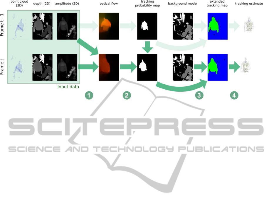
Figure 3: Processing pipeline for newly acquired ToF frame at time t. (1) A flow field is calculated based on amplitude
images of frame t-1 and frame t. (2) The flow field is applied to the tracking probability map of frame t-1, resulting in a
tracking probability map for frame t. (3) The tracking probability map is processed based on the tracking information of
frame t-1 and a global background model to provide an extended tracking map. (4) Applying the extended tracking map to
the point cloud results in the final tracking estimate.
processing pipelines which are executed in parallel.
The first one processes all data acquired by the ToF
camera (data which doesn’t contain any tracking
information) and propagates tracking information
based on the delayed ground truth. Thereby, a
tracking estimate is provided in each time step. The
second one processes the user tracking information
from the Kinect camera (ground truth) and updates
the ToF tracking state as well as the background
model.
3.1.1 ToF Processing
In the following, we use the term “ToF frame” to
refer to all ToF data associated to a single time step:
source data such as the 3D point cloud, the
amplitude image, the depth image and the time
stamp of the data acquisition as well as processed
data such as a flow field, a tracking probability map
and geometric information about tracked targets. To
enable applying the results of filtering in the 2D
image domain to the 3D space of the point cloud, the
pixel-to-point correspondences have to be preserved.
For this reason, only operations are employed on the
ToF point clouds that keep them organized, i.e. that
don’t alter the original points in the cloud.
Figure 3 visualizes the data processing of
incoming ToF frames: Upon receiving a new ToF
frame, the point cloud is transformed into a shared
coordinate system and 2D optical flow from the
previous frame is calculated based on the respective
amplitude images (see Section 3.3). The ToF frame
is then stored in a ring buffer. A tracking probability
map is calculated that provides a first estimation of
the current position of the tracked target(s), based on
the optical flow and the tracking probability map
stored in the previous ToF frame. Last, a refinement
and rejection step is performed based on the tracking
probability map, the background model and the
spatial information encoded in the depth map (see
Section 3.5). This yields the extended tracking map
for the current time step which is then applied to the
point cloud to calculate the human body point cloud
tracking estimate.
3.1.2 Ground Truth Processing
Upon reception, the point cloud corresponding to the
tracked human(s) is transformed to the shared
coordinate system. Based on the acquisition time of
the received point cloud, the closest matching ToF
frame is located in the ring buffer (see Figure 4). By
determining correspondences between the ground
truth and the point cloud stored in the ToF frame, a
tracking probability map with full certainties is
established and the ToF frame is marked as a key
frame. The background model is updated using this
tracking probability map and the corresponding
depth map (see section 3.2). These calculations are
performed for each incoming ground truth frame and
are therefore independent of the actual delay of the
ground truth.
Using the respective flow fields, the tracking
probability map is propagated forward throughout
the ring buffer until the most recent ToF frame (see
Section 3.4). Here, the number of forward-
propagations is directly proportional to the length of
the delay. Thereby, the tracking probability map of
ContinuousPre-CalculationofHumanTrackingwithTime-delayedGround-truth-AHybridApproachtoMinimizing
TrackingLatencybyCombinationofDifferent3DCameras
123
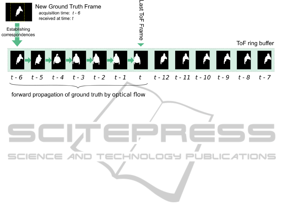
Figure 4: Processing pipeline of new ground truth data acquired at time t-6 and is received at time t. First, the corresponding
ToF frame in the ring buffer is identified using the associated time stamps. Next, correspondences are estimated to calculate
a tracking probability map for the ToF frame at time t-6. Last, the tracking probability map is propagated forwards using the
flow fields associated with each ToF frame.
the next arriving ToF frame will be calculated based
on the updated information from this frame.
3.2 Background Modelling
In the presented approach, almost all information is
stored and processed on a frame-by-frame basis, e.g.
optical flow between two frames and the tracking
probability map are directly assigned to a specific
ToF frame. There are two exceptions which are
modelled as global components: The number of
tracked humans and a background model of the
scene.
Our approach to modelling the background of the
scene is based on the works of (Zivkovic, 2005) that
extended the common Gaussian mixture models for
pixel-wise background subtraction by an automatic
calculation of the correct number of Gaussian
distributions per pixel. We have modified the
OpenCV implementation of this algorithm in two
ways in order to take advantage of the data flow in
our approach. First, we introduce a masking
capability that enables restricting an update of the
background model to specific areas of the image.
Second, we split the update step of the original
algorithm into two different parts: A background
maintenance that only updates the model (without
performing background subtraction on the input) and
a foreground detection stage that allows performing
background subtraction on an image and calculating
a foreground mask without updating the background
model.
Based on these modifications, the background
model is being used as follows:
When a new ground truth frame arrives and
correspondences to the according ToF frame have
been calculated, the background model is updated
using the depth image of this ToF frame. The
tracking probability map is used to mask the tracked
humans, thereby ensuring that they are not
incorporated into the background model. This
prevents the common problem that non-moving
entities will be included in the background after a
certain number of update-steps (Sobral, 2014).
When a new ToF frame is processed, an
extended tracking map is calculated that contains the
location of all pixels belonging to a tracked human.
However, this map is prone to inclusion of false
positives, e.g. pixels that belong to the background.
For correction, a foreground mask is retrieved by
querying the background model with the depth
image of the ToF frame. By masking the extended
tracking map with the foreground mask, we remove
potential false positives.
3.3 Optical Flow Estimation
As described in Section 3.1.2, optical flow applied to
2D images is used to propagate the tracking
probability map between the ToF frames.
When using RGB images, the sensitivity of
optical flow for moving targets such as humans or
objects is highly dependent on the kind of motion
performed. When applying optical for the purpose of
tracking, rotations prove more difficult to detect than
translations: During rotation of a tracked target,
previously visible parts of the object vanish from the
image while new parts appear. For these new
elements, no corresponding parts exist in the
previous image. Performing optical flow
ICINCO2015-12thInternationalConferenceonInformaticsinControl,AutomationandRobotics
124

calculations on the amplitude images acquired by
ToF cameras partially overcomes this problem: The
reflectivity of a tracked target, especially in the case
of human tracking, is usually less affected by
rotations than its appearance in color space.
For the actual calculation of optical flow
between two amplitude images, we use the TV-L1
algorithm proposed by (Sanchéz, 2013). The flow
field is calculated upon receiving a new ToF frame
and stored within the frame. As the flow field based
propagation of the tracking probability map is only
used as a first approximation which is refined in
subsequent steps, our parameterization of the optical
flow algorithm is targeted on a higher computation
speed rather than an optimal accuracy. Therefore, we
set the number of warps to 2 with 3 levels.
3.4 Tracking Probability Propagation
In ToF frames, information about the location of
tracked humans has to be stored and propagated. We
represent this information as a 2D probability map
where the value of each pixel denotes the probability
of this pixel belonging to a tracked human.
When a ground truth frame is received and the
ToF frame with the closest matching timestamp was
located in the ring buffer, point-to-point
correspondences between both frames have to be
established. These correspondences are calculated
by creating a k-d-tree of the downsampled ground
truth cloud, iterating over all points in the ToF point
cloud and determining whether the distance to the
ground truth cloud is smaller than a pre-defined
threshold. For all points where this check is
successful, the according pixel in the zero-initialized
probability map is set to one.
Propagation of the tracking probability map from
ToF frame F
t
to subsequent frame F
t+1
is performed
using the flow fields associated with each ToF
frame: Using the flow field, each pixel p
i,t
with a
positive probability value is projected onto the
tracking probability map of frame F
t+1
. To map its
new coordinates (x
i,t+1
, y
i,t+1
) to whole-numbered
coordinates, the probability value associated with p
i,t
is distributed onto the four adjacent pixels p
j1,t+1
..
p
j4,t+1
based on their L2 distance to the new position,
provided that these pixels are inside the region of the
image.
In addition to populating the tracking probability
map, the current total number of tracked targets is
determined based on the ground truth frame and
stored as part of the global tracking state.
3.5 Tracking Estimation
At the arrival of each new ToF frame, a tracking
probability map is calculated that provides a first
estimation which points in the point cloud
correspond to the tracked human. However, this
estimation has to be refined due to potential errors
introduced by the flow field based propagation of
the tracking probability. In our experience,
especially human extremities such as arms are prone
to misdetection during optical flow propagation with
low-resolution ToF cameras (false negatives). Also,
tracking probabilities might be erroneously
associated to non-tracked objects in the surrounding
environment (false positives).
For this reason, the tracking estimation step is
split into two stages: tracking refinement stage and
outlier rejection stage.
3.5.1 Tracking Refinement Stage
The tracking refinement stage is primarily targeted
at correcting false negative detections, e.g. non-
detected extremities. The tracking probability map is
first binarized by comparison against a pre-defined
threshold and then segmented into connected
probable tracking regions r
i
. For each region, the
center of mass m
i
is calculated. Using m
i
as a seed, a
floodfill operation is performed on the associated
depth image in order to connect previously
undetected pixels with local continuity in 3D space.
The result is a refined tracking estimate r
i
’ for each
connected region.
3.5.2 Outlier Rejection Stage
While false negative detections have been resolved
in the previous stage, there is still a possibility for
false positive detections to be present due to
erroneous propagation of the tracking probability
map onto untracked pixels. To reject these outliers,
the current number of probable tracking regions is
first checked against the number of tracked targets
(see Section 3.4). If there are more regions than
tracked targets, we perform a similarity comparison
between each tracked region r
j,t-1
’ of the last frame
and all current probable tracked regions r
i,t
’ in order
to detect the correct correspondences. The similarity
comparison is based on both 2D similarity metrics
(e.g. 2D center location and area of a region) and 3D
similarity metrics (e.g. Euclidean distance between
the center points in 3D space). For each region r
j,t-1
’
of the previous frame, the best matching region r
i,t
’
is determined and its features are stored as detected
tracked regions in the current ToF frame. In order to
ContinuousPre-CalculationofHumanTrackingwithTime-delayedGround-truth-AHybridApproachtoMinimizing
TrackingLatencybyCombinationofDifferent3DCameras
125
avoid merging of multiple regions r
j,t-1
’ onto a single
region r
i,t
’, regions r
i,t
’ are exempt from further
similarity comparisons once they have been
successfully matched.
As a last step, for each detected tracked region
all corresponding points in the ToF frame cloud are
selected. This results in the full body point cloud of
the respective tracked human being available for
further processing.
4 RESULTS
The developed algorithm has been evaluated in the
two scenarios presented in Sections 2.1 and 2.2.
Evaluation was performed by comparing the
extended tracking map, which is calculated
immediately on the arrival of each new ToF frame,
against the corresponding ground truth, which
becomes available with a certain delay. This also
means that only frames for which a corresponding
ground truth was received are taken into account.
All tests were performed under Linux Ubuntu
12.04 using an AMD Phenom II 1090T processor
with six cores at 3.2 GHz and 12 GB of RAM. All
cameras have been registered against an optical
tracking system.
Table 1 lists the metrics employed for accuracy
evaluation.
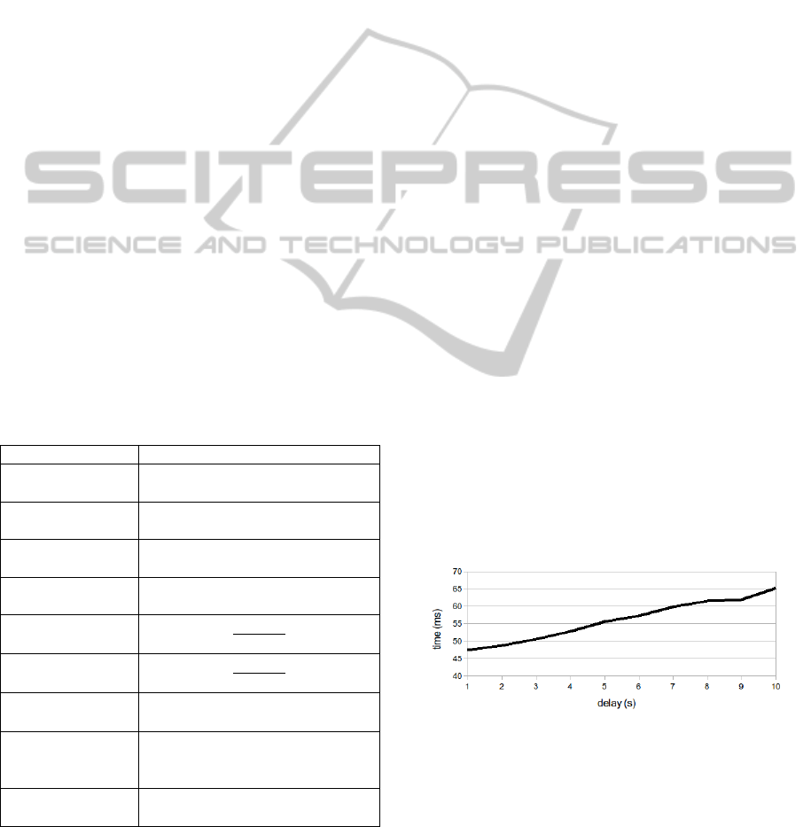
Table 1: Metrics for accuracy evaluation.
Metric Definition
True positives tp
Pixels correctly classified as part
of the tracked human
True negatives tn
Pixels correctly classified as not
part of the tracked human
False positives fp
Pixels incorrectly classified as
part of the tracked human
False negatives fn
Pixels incorrectly classified as not
part of the tracked human
Precision
ݐ
ݐ
݂
Recall
ݐ
ݐ
݂
݊
ToF frame
processing time
Time required for processing a
single ToF frame (ms)
Ground truth
processing time
Time required for forward
propagation of the ground truth of
a single Kinect frame (ms)
Tracking loss
Percentage of frames with
complete loss of tracking
4.1 Latency Minimization
For the latency minimization scenario, evaluation
was performed on two recorded data sets. Set A has
a duration of 53.5 seconds, contains 317 ToF frames
and 265 ground truth frames. The cameras are
located with a distance of 31.2 cm between each
other and share the same field of view. The desired
latency for evaluation was artificially introduced by
playing back the Kinect data with a delay between 1
and 10 seconds. The average processing time per
ToF frame was 39 ms, independently of the induced
delay.
In set A, the tracked person comes into the field
of view two times. To allow for a detailed
examination, evaluation has been performed on two
different subsets of the measurements: A1 takes into
account all frames of each measurement, A2
includes only the frames in which recall and
precision were positive, i.e. tracking was actually
performed. As a consequence, subset A1 is directly
influenced by the delay of the ground truth: On entry
of a person into the field of view, there is no ground
truth available until the delayed ground truth is
received. A higher delay therefore directly results in
more frames in which no forward propagation
happens and no tracking is performed which in turn
lead to a higher rate of false negative classifications
and thereby a lower recall.
In all following figures, obtained results are
shown over the respective delay; the continuous line
corresponds to subset A1 whereas the dotted line
corresponds to subset A2. All reported results are
averaged over all frames of each measurement.
Figure 5 shows the ground truth processing time.
Figure 6 and Figure 7 show the numbers of false
negative and false positive classifications. Figure 8
shows the resulting precision of the tracking
estimate and Figure 9 shows the achieved recall of
the tracking estimate.
Figure 5: Ground truth processing time (shown for subset
A1 only).
Set B was recorded with the aim of evaluating
the proposed algorithm in terms of robustness
against data acquired from different points of view.
It contains data of six ToF cameras that are
ceiling-mounted in four corners as well as on the
sides of a rectangle of about 2 m x 2 m (see Figure
ICINCO2015-12thInternationalConferenceonInformaticsinControl,AutomationandRobotics
126
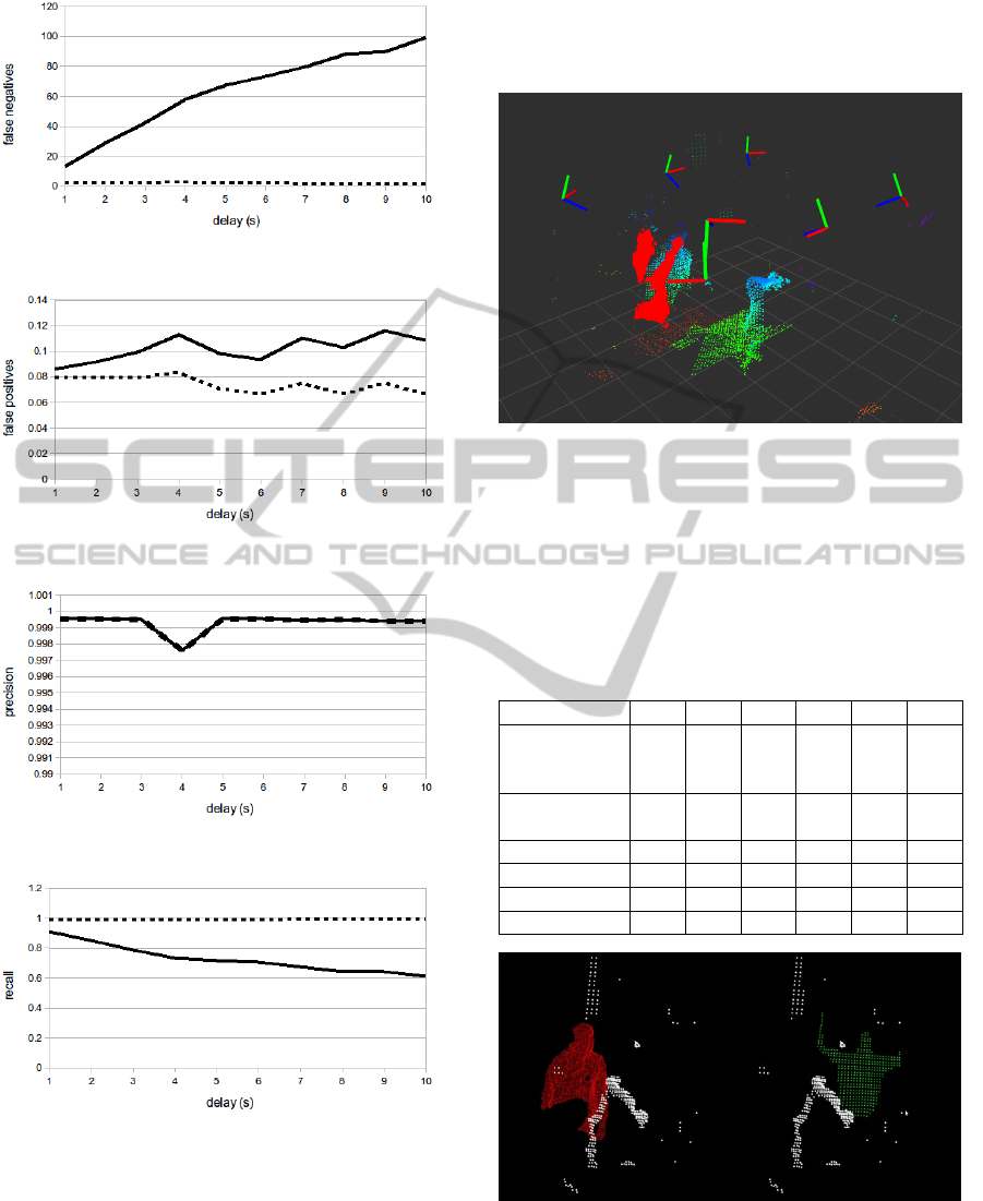
Figure 6: Number of false negative classifications.
Figure 7: Number of false positive classifications.
Figure 8: Precision of the tracking estimate.
Figure 9: Recall of the tracking estimate.
10). A Kinect camera mounted in one of the corners
is used as ground truth. Set B has a duration of
85 seconds, contains approximately 230 ToF frames
per camera and 294 ground truth frames. Again, the
results are split into two subsets B1 and B2 where
B2 only contains frames where a detection was
performed. Further information about the spatial
relation between each ToF camera and the Kinect
camera as well as the achieved results (recall and
precision) for both subsets B1 and B2 are shown in
Table 2.
Figure 10: Spatial configuration of cameras (displayed as
axes): six ToF cameras (y-axis pointing upwards) and one
Kinect camera (front, y-axis pointing downwards). The
combined point cloud depicts the surface center of an OR
table (green) with an attached robot arm (turquoise) as
well as the delayed ground truth (red) with the current
human position visible directly behind it (green/turquoise).
Table 2: Spatial configuration and accuracy evaluation for
six ToF cameras with different points of view compared to
the Kinect camera and latency of 1 s.
1 2 3 4 5 6
Angle
compared to
Kinect (est.)
0° 90° 90° 180° 45° 135°
Distance to
Kinect (cm)
31 163 192 251 92 189
Recall B1
.71 .71 .80 .66 .80 .64
Precision B1
.99 .96 .97 .88 .97 .92
Recall B2
.90 .90 .91 .96 .91 .96
Precision B2
.99 .90 .97 .88 .97 .96
Figure 11: Delayed ground truth (left scene, red) and pre-
calculated tracking estimate (right scene, green) in latency
minimization scenario.
Figure 11 shows a side-by-side exemplary view
of the point cloud of a single ToF camera with the
ContinuousPre-CalculationofHumanTrackingwithTime-delayedGround-truth-AHybridApproachtoMinimizing
TrackingLatencybyCombinationofDifferent3DCameras
127
delayed ground truth and the pre-calculated tracking
estimate for this scenario.
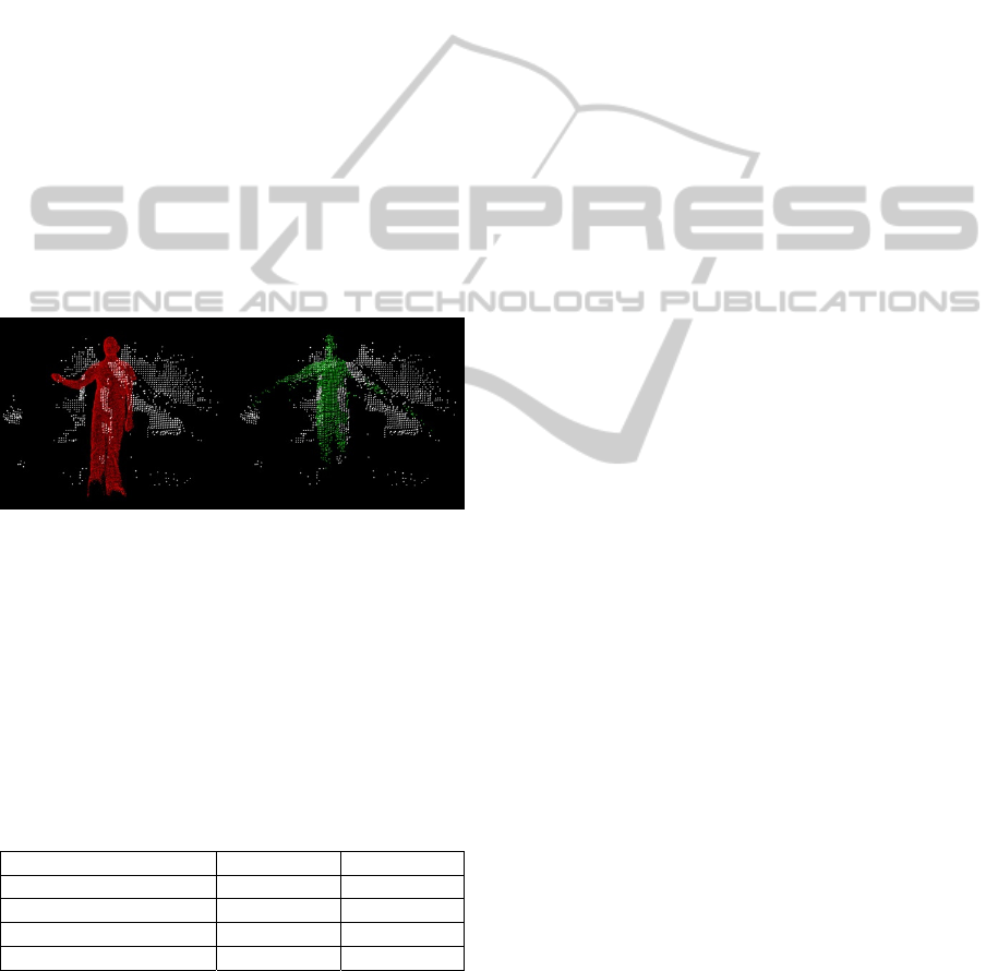
4.2 Frame Rate Optimization
Contrary to the camera system used in the scenario
above, which has already been well-tested and
optimized, e.g. with regards to crosstalk of the
different cameras illuminating the scene with
infrared light, the combination of the Kinect II with
the Argos 3D P100 is employed as a proof of
concept for the purpose of evaluating the presented
algorithm. Currently, the maximum frame rate of
160 fps for the Argos camera can only be achieved
with a low integration time that drastically decreases
the sensing range of the camera. As a compromise,
we operated the camera at 80 fps which yielded an
acceptable sensing range for object with a medium
to high reflecivity (i.e. people wearing white
clothes). In addition, we observed infrequent
crosstalk. Figure 12 shows the pre-calculation with
the Argos 3D P100.
Figure 12: Delayed ground truth (left scene, red) and pre-
calculated tracking estimate (right scene, green) in frame
rate optimization scenario.
Evaluation was performed using four different
data sets of lengths between 30 s and 68 s. Each data
set contains at least 2.300 frames acquired by the
ToF camera and 600 frames taken by the Kinect II.
Again, the measurements were split as before into
subsets C1 and C2.
Table 3: Accuracy evaluation for high frame rate ToF at
normal and reduced speed.
1x Speed 0.1x Speed
Average Recall C1
0.73 0.87
Average Precision C1
0.87 0.90
Average Recall C2
0.96 0.94
Average Precision C2
0.95 0.91
As the processing of each ToF frame took more than
230 ms on average, which resulted in dropped
frames, we slowed back the playback of the recorded
data by a factor of 10. In proportion, this
corresponds to a processing time of about 20 ms, and
can serve as an indication for the potential accuracy
of the algorithm. Table 3 lists the resulting accuracy
metrics.
5 DISCUSSION
For the latency minimization scenario, Figure 5
shows that the ground truth processing time starts at
47 ms at a delay of 1s and increases with longer
delays. This corresponds to a first processing step of
about 45 ms, in which transformation of the ground
truth cloud and correspondence calculation are
performed, followed by the forward propagation of
the ground truth which takes about 1.7ms per second
of delay and is therefore also applicable to longer
delays.
The total latency of the pre-calculated tracking
can be calculated as the sum of the latency of the
ToF cameras in the six-camera setup of about
240 ms and the ToF frame processing time of 39 ms.
The resulting total latency of less than 300 ms is
independent of the induced delay, so the observed
speedup of the tracking is between 3x and 33x for a
respective delay of 1 s to 10 s.
As expected, the number of false negative
classifications as depicted in Figure 6 is
approximately proportional to the induced delay for
the subset A1 (see in Section 4.1). For subset A2,
from which frames without a ground truth were
excluded, the number of false negative
classifications was negligible and clearly
independent of the delay. The number of false
positive classifications is not dependent on the delay
and also negligible (see Figure 7).
These results lead to a high precision (see Figure
8), e.g. close to nil points are erroneously classified
as belonging to the tracked human. For subset A1,
recall is again proportional to the delay as with a
higher delay, there is no ground truth for a large
number of frames. If only frames for which a ground
truth was available during the measurement are
taken into account (subset A2), recall is close to 1
which means that almost all points that belong to the
tracked human have been classified as such (see
Figure 9).
Measurements with six ToF cameras show that
the proposed algorithm shows good results also on
different camera configurations, i.e. when the ToF
camera and the Kinect camera are not mounted with
a similar point of view, as can be seen from Table 2.
Subset B1 shows worse results on recall than subset
B2, due to the fact that with different fields of view,
the tracked human is often not visible in both
ICINCO2015-12thInternationalConferenceonInformaticsinControl,AutomationandRobotics
128

cameras at once, so no correspondences can be
established. For the six-camera scenario specifically,
we expect to solve this by utilizing the fused output
of four spatially distributed Kinect cameras as
ground truth.
The rather long processing time when using the
Argos 3D P100 camera is consistent with the
timings measured for the pmd[vision] S3 cameras:
The Argos3D P100 nominally provides about six
times more points per frame, for which
correspondences have to be determined, which leads
to an increase in processing time from 46ms to about
230ms. However, this calculation is currently
performed on CPU in a single thread so we are
expecting to achieve a large speedup by parallelizing
on CPU and/or GPU. Further optimizations of the
frame rate and image quality are expected by using a
different high-speed ToF camera, the upcoming
Argos 3D P320, which features 12 instead of 2
LEDs for illumination and thereby increases the
effective sensing range.
6 CONCLUSIONS
We have proposed a new approach for pre-
calculating the body point cloud of a human based
on time-delayed ground truth. It features two distinct
processing pipelines: One pipeline processes the
ground truth, that corresponds to a past measurement
frame, and propagates it forward to the current
frame. The other pipeline handles the incoming data
from the faster 3D camera system and calculates a
tracking estimate based on 2D optical flow in
combination with a customized background model
and various refinement steps.
The algorithm has been implemented and
evaluation has been performed on two different
scenarios. Results for the latency minimization
scenario show that the presented approach
consistently achieves very good results for the
evaluated data sets. The distinction between two
different data sets for each evaluation shows that
apart from the initial delay until a tracking is
established, the magnitude of the latency doesn’t
affect the high tracking quality of the algorithm.
While still good, the accuracy of the second scenario
is lower than that of the first scenario and the current
processing time prohibits its intended usage. For this
reason, optimization of the algorithm in terms of
computational costs and the optimization of our test
bed for the second scenario will be addressed as
detailed above.
In addition, we plan to integrate the algorithm
into the full OP:Sense supervision system by pre-
calculating human tracking simultaneously on all six
ToF cameras, based on fused ground truth from four
different Kinect cameras. We envision that the
fusion of the results will further improve the
accuracy and thereby provide a reliable modality to
be used for human-robot interaction. Also, we aim to
apply the algorithm to other kinds of tracking
scenarios using different input modalities.
ACKNOWLEDGEMENTS
This work was funded by the European
Commission’s Seventh Framework program within
the project ’Active Constraints Technologies for Ill-
defined or Volatile Environments (ACTIVE)’ under
grant no. 270460.
REFERENCES
Beyl, T. et al., 2013. Multi Kinect People Detection for
Intuitive and Safe Human Robot Cooperation in the
Operating Room. In ICAR ’13, International
Conference on Advanced Robotics, pp. 1 – 6.
Bradski, G. R., Pisarevsky, V., 2000. Intel’s Computer
Vision Library: Applications in calibration, stereo,
segmentation, tracking, gesture, face and object
recognition. In CVPR’00, IEEE International
conference on Computer Vision and Pattern
Recognition, vol. 2, pp. 796 – 797.
Jóźków, G., et al., 2014. Combined Matching of 2D and
3D Kinect ™ Data to support Indoor Mapping and
Navigation. In Proceedings of Annual Conference of
American Society for Photogrammetry and Remote
Sensing.
Klappstein, J. et al., 2009. Moving Object Segmentation
Using Optical Flow and Depth Information. In
Lecture Notes in Computer Science: Advances in
Image and Video Technology, vol. 5414, pp. 611 –
623.
Moennich, H. et al., 2011. A supervision system for the
intuitive usage of a telemanipulated surgical robotic
setup. In ROBIO ’11, IEEE International conference
on Robotics and Biomimetics, pp. 449 – 454.
Okada, R., Shirai, Y., Miura, J., 2000. Tracking a person
with 3-D Motion by Integrating Optical Flow and
Depth. In Fourth IEEE International Conference on
Automatic Face and Gesture Recognition, pp. 336–
341.
Quigley, M. et al., 2009. ROS: an open source Robot
Operating System. In ICRA ’09, International
Conference on Robotics and Automation Workshop
on Open Source Software.
Rusu, R. B., Cousins, S., 2011. 3D is here: Point Cloud
Library (PCL). In ICRA ’11, International Conference
ContinuousPre-CalculationofHumanTrackingwithTime-delayedGround-truth-AHybridApproachtoMinimizing
TrackingLatencybyCombinationofDifferent3DCameras
129

on Robotics and Automation, pp. 1 – 4.
Sanchéz, J., Meinhardt-Llopis, E., Facciolo, G., 2013. TV-
L1 Optical Flow Estimation. In: Image Processing On
Line, vol. 3, pp. 137–150.
Sobral, A., Vacavant, A., 2014. A comprehensive review
of background subtraction algorithms evaluated with
synthetic and real video. In Computer Vision and
Understanding, vol. 122, pp. 4 – 21. Elsevier.
Tsutsui, H., Miura, J., Shirai, Y., 2001. Optical Flow-
Based Person Tracking by Multiple Cameras. In
International Conference on Multisensor Fusion and
Integration for Intelligent Systems, pp. 91 – 96.
Zivkovic, Z., Heijden, F., 2005. Efficient adaptive density
estimation per image pixel for the task of background
subtraction. In Pattern Recognition Letters, vol. 27,
pp. 773 – 780.
ICINCO2015-12thInternationalConferenceonInformaticsinControl,AutomationandRobotics
130
