A Trajectory Tracking Control of a Skid Steered Mobile Cleaning
Robot
Seungwoo Jeon
1
, Wootae Jeong
2
, Soon-Bark Kwon
2
, Cheulkyu Lee
2
and Duckshin Park
2
1
Department of Robotics & Virtual Engineering, Korea University of Science and Technology, Daejeon, Korea
2
Transportation Environmental Research Team, Korea Railroad Research Institute, Gyeonggi-do, Uiwang, Korea
Keywords: Mobile Platform, Four Wheel Skid Steering, Trajectory Tracking, Mass Center.
Abstract: Cleaning accumulated dusts inside air ventilation ducts of underground facilities is an essential process to
improve indoor air quality, especially at the underground facilities such as subway platforms. Therefore,
various autonomous mobile duct cleaning robots have been actively studied to be applied at the closed space
of the ventilation duct. In this paper, the four wheeled skid steering mobile platform with rotating brush-
arms has been developed and proposed an effective skid steering control technique under changeable center
of mass (CM) of the platform. The shifted CM of the platform and unstable disturbances acting on the
rotating brushes from cleaning surfaces can change the dynamic steering characteristics of the platform.
Therefore, this paper also proposes a new integrated backstepping and I-PD controller for stable trajectory
tracking of the platform and proves the effects of the controller through simulations.
1 INTRODUCTION
HVAC ducts have to be cleaned regularly to
improve indoor air quality that can affect the health
of people. The mechanical brushing method was
reported as the most efficient duct cleaning method
among various duct cleaning methods (Holopainen
et al, 2003). Nevertheless, the most of air ventilation
ducts at many industrial facilities has been still
cleaned by the human. To increase efficiency and
safety in cleaning inside air ducts, various
autonomous duct cleaning technologies have been
suggested by using mobile platforms (Jeon et al,
2013).
The autonomous mobile cleaning robot without
steering system requires skid-steering technique for
trajectory-tracking control. Since the skid-steering
uses the velocity difference between two wheels, the
platform can be modelled with a non-holonomic
constraint based on the specific kinematic and
dynamic characteristics (Caracciolo et al, 1999).
However, the singularity problem can be occurred at
pivot-turning: the velocity at the center of mass(CM)
becomes zero. To avoid the singularity problem
from the estimated dynamic model, a backstepping
technique was used to provide feedback for the
current velocity of the platform equipped with
steering mechanism (Fierro et al, 1997). Tracking
error should be minimized to increase pressurizing
force for the brush to the workspace (Jeong et al.,
2012).
However, the CM of the platform is also
changeable by reciprocating motion of the upper
brush-arm and dynamic disturbances occurred from
nonlinear friction between brush and duct surface
make the tracking error increase. These trajectory
tracking errors can be reduced by applying an
additional neural-network controller with a fully
unattainable parameter such as a friction coefficient
between wheel and the floor of ducts(Fierro et al,
1997). However, implementing the training process
of a neural-network or adaptive logic requires a high
speed processor and long computational time (Kim
et al, 2006).
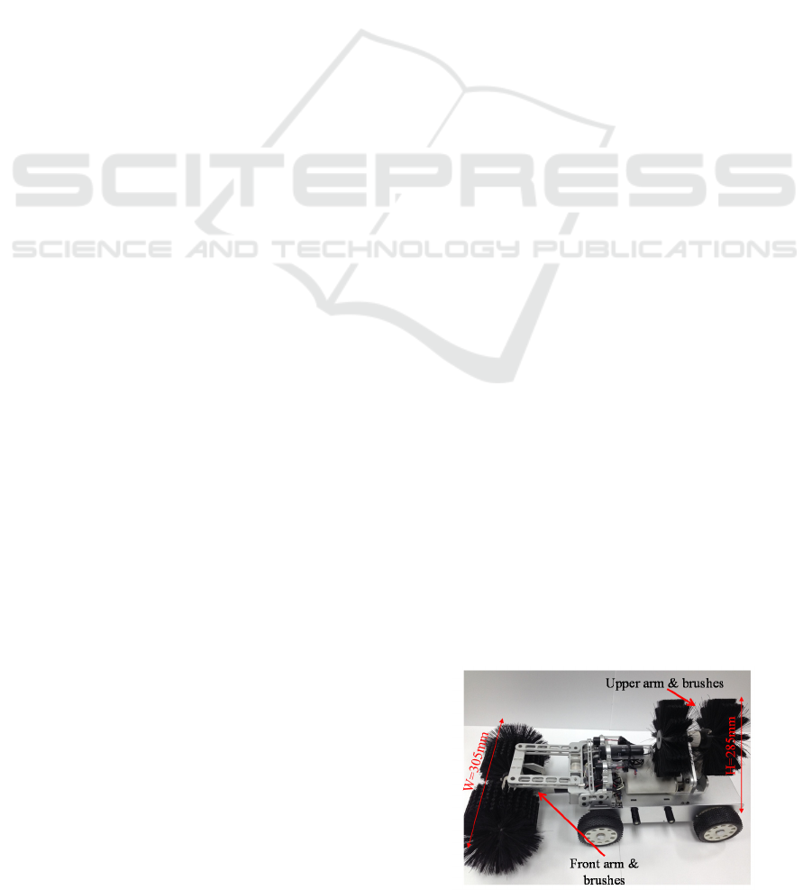
Figure 1: Prototype of the duct cleaning robot.
375
Jeon S., Jeong W., Kwon S., Lee C. and Park D..
A Trajectory Tracking Control of a Skid Steered Mobile Cleaning Robot.
DOI: 10.5220/0005562403750380
In Proceedings of the 12th International Conference on Informatics in Control, Automation and Robotics (ICINCO-2015), pages 375-380
ISBN: 978-989-758-123-6
Copyright
c
2015 SCITEPRESS (Science and Technology Publications, Lda.)
In this paper, a simple and robust control method
is proposed to enable the stable trajectory tracking of
the duct cleaning robot to reduce the effect of
uncertainties occurred by shifting CM of the
platform.
Figure 1 shows the prototype of the duct cleaning
robot which has two robotic arms and rolling
brushes for cleaning inside duct.
2 DYNAMIC ANALYSIS
2.1 Modelling of the Mobile Platform
For the trajectory tracking control of the mobile
platform, a mathematical model of the platform was
presented by considering both kinematic and
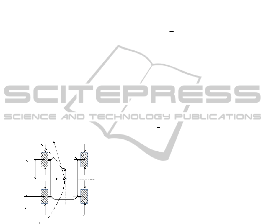
dynamic characteristics. As depicted in Figure 2, the
fixed coordinate system was set to q=[X, Y,
φ
], the
posture angle,
φ
, of the platform was the same as
the yaw angle, and the moving coordinate system [x,
y,
φ
] was defined to be placed at the center of
mass(CM) of the platform. The wheel slip was
neglected.
Figure 2: A schematic model of the mobile platform.
Based on the schematic model of the mobile
platform illustrated in Figure 2, the equation of
motion of the platform can be given by Example:
44
11
,
xi xi
ii
xF Rmy
φ
==
=+−
m
φ
=
=− +
4
1
m
yi
i
y
Fmx
,
12
().
φ
−−=
x
xr
WIFFM
(1)
where F
xi
is the tractive force at the contact point of
the wheel, R
xi
is the longitudinal resistive force of
the wheel, F
yi
is the lateral force at the contact point
of the wheel(Caracciolo et al, 1999). By assigning
friction coefficients (
,
x
y
μ
μ
) as a constant, the
resistive force, lateral force, and resistive moment at
the CM can be calculated as
44
11
sgn( ),
4
μ
==
==
xxix
ii
i
mg
R
Rx
(2)
4
13
1
(sgn( ) sgn( )),
yyiy
i
mg
F
Fyy
L
μ
=
== +
(3)
()
()
1234
2314
2
.
2
ryyyy
xxxx
L
MFFFF
W
RRRR
−−
+−−
=+
+
(4)
The dynamic model of the platform with
generalized coordinates,
(,,)
φ
=qXY can be
expressed as a matrix form by
()
(,)=−Mq E q τ F
qq
()
00
00, ,
00
1
sin s
c
in , 2 ( 1,2)
os sin
sin co
,
s
/2 /2
φ
φ
φ
φφ
φ
φφ
==
===
−
−
+
M F(q,q)
Eq τ
xi
xy
xy
r
m
m
I
cos cos
rF i
r
WW
RF
RF
M
(5)
where r is the wheel radius,
τ
are the torques at left
and right side of motors to drive wheels. To
accomplish the skid steering by creating a
differential velocity between left and right side of
wheels, the kinematic equation concerning about the
platform velocity, v, can be written by
2
(),=∈
qSqvvR
(6)
()
0
0
01
cos
sin ,
φ
φ
=
Sq
(7)
where
[]
12
,,
==
T
T
linear angular
vv vvv
refers to the linear
and angular velocity vector at the CM and S(q) is 3
☓2 matrix for coordinate transformation.
Since front and rear wheels are directly
connected with V-belts, the four-wheel skid-steering
platform can be considered as a two-wheel
differential driven mobile platform(Martinez et al,
2005). The equation of motion for the platform with
nonholonomic constraint can be presented as
()
()
()
,
λ
=−
=−
T
Mq E q τ + A q F(q,q)
Eqτ F(q,q)
[]
() sin cos 0 0
X
Y
φφ
φ
=− =
Aqq
(8)
y
x
R
x1
W
L
ϕ
R
x2
R
x3
R
x4
F
x1
F
x2
F
x3
F
x4
F
y1
F
y2
F
y4
F
y3
X
Y
2
L
ICINCO2015-12thInternationalConferenceonInformaticsinControl,AutomationandRobotics
376
From the Equation (6) and Equation (8), the state
feedback control law becomes
()
()
1
,
−
=++
TT T T
τ SE SMSu SMSv SF
(9)
where
12
[, ]==
vvuv
refers to the control input.
As the platform moves, the upper brush arm on
the mobile platform makes duct surface cleaned by
reciprocating mechanism. The CM of the platform
can be shifted by the motion of the upper brush arm.
Consequently, the yaw moment of the platform can
be changed. Therefore, for trajectory tracking
control, steering commands calculated by torques of
traction motors have to be determined by
considering the dynamic shifts of the CM (see
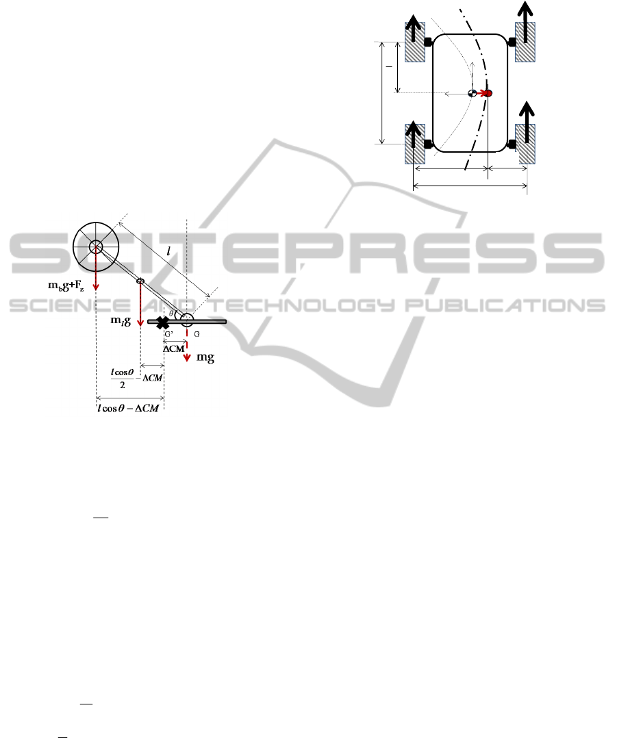
Figure 3).
Figure 3: Simplified model of the upper rotating brush
arm.
The shifting position of the CM can be calculated
as
,
θ
Δ= = ,
b
xx
m
CM L L lcos
m
(10)
where l is the length of the brush arm,
CMΔ
is a
shifted distance of the CM in the lateral direction, m
b
is the mass of the rotating brush, and m is the overall
mass except the brush and arm. The rotation angle of
the brush arm,
θ
, ranges from 0 to 180 [deg] as
shown in Figure 3. As the CM changes, the yaw
moment of the platform is changed. Thus, the
resistive moment of the Equation (4) can be
recalculated as follows
,
2
L
W
WCM=−Δ
,=+
RL
WW W
()
()()
1234
23 14
2
ryyyy
Rx x Lx x
L
MFFFF
WR R WR R
=+
++−+
−−
.
(11)
By considering the shifted CM position as depicted
in Figure 4, the yaw moment change and velocity
changes are required for accurate steering control of
the platform.
Figure 4: A scheme of skid-steering motion with the
shifting center of mass(CM) of the platform.
2.2 Trajectory Tracking Control
In order to control the platform as a given trajectory,
dynamic uncertainties by the CM position changes
and rubbing force by brush-arm need to be
considered to determine the control inputs and motor
torques. Additionally, the tracking control has to be
designed to make the pivot-truning which can cause
uncontrollerable with zero velocity at the CM.
Therefore, The integrator backstepping method
can be applied with incomplete dynamic model of
the nonholonomic system. The error vector, e,
between the target point on the given trajectory and
the platform location and the differential vector of
the error vector can be expressed as
()
,
r
eTq q=−
cos sin 0
sin cos 0
001
,
φφ
φ
φφ
φ
∅
−
== −
−
−
xr
yr
r
eXX
eYY
e
e
()
12
2
2
cos( )
sin sin .
yr
xr
r
vve x e
ve x e
v
φ
∅
∅
−+ +
=− +
−
e
(12)
The derivative of the platform target velocity,
c
v
,
for trajectory tracking can be calculated as
()
1
23
cos( )
,
sin sin
rx
rryr
xeke
kxe kx e
φ
∅
∅
+
=
++
c
v
()
()
23
1
23
cos cos
0sin()
.
0c
si
os )
n
(
ryrr
r
r
rr
xe
kke
kxe
kk
ex
xe
x
x
φ
φ
φ
φ
φ
=
++
−
+
c
v
e
(13)
y
x
v
l
v
r
W
L
F
1
F
2
F
4
F
3
W
L
W
R
CMΔ
2
L
ATrajectoryTrackingControlofaSkidSteeredMobileCleaningRobot
377
where
c
v
can be applied to the concept of the perfect
velocity tracking to obtain the control input
expressed in Equation (9). However, it is infeasible
for an actual platform to be controlled at a target
velocity without feedback of velocity errors in the
trajectory tracking. Therefore, the control input can
be expressed with feedback of the platform velocity
as follows
()
4
,
=+ −
cc
uv Kv v
(14)
where
4
K
can be a positive definite, diagonal matrix
4
k=
4
KI
.
Additionally, using the Lyapunov function, the
error vector (e) of Equation (12) can asymptotically
converge to zero value as proven by (Fierro et al,
1997). Nevertheless, when dynamic uncertainties are
occurred by shifting CM and the pressurizing force
applied by the brush-arm, stability of the trajectory
tracking cannot be assured. To obtain additional
control input for reducing the position error, simple
PID controller can be adopted. However, the traction
motor can be damaged by the derivative (D)
controller which magnifies the input signal with
disturbances. Thus, a digital I-PD controller, whose
proportional(P) and derivative(D) controller are
feedbacked by actual measurement values, can be
implemented by placing low pass filter in front of D
controller (King et al, 2010).
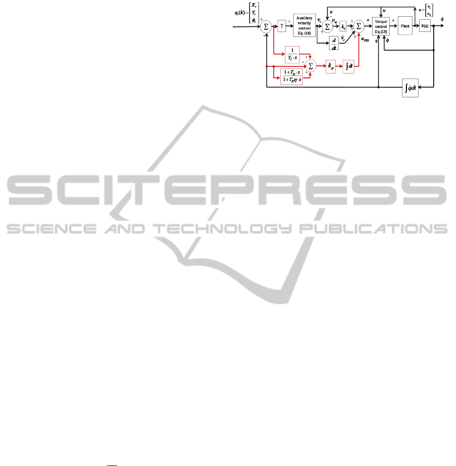
Figure 6 shows the control flow scheme
integrating the Backstepping method and the I-PD
controller for trajectory tracking control of the
platform. The I-PD controller can be converted to
discrete form and expressed as Equation (15). The
new control input can be obtained by integrating the
I-PD controller and the Backstepping controller of
the velocity, as expressed in Equation (16)
,,1 ,
,
PID k PID k PID k
−
=+Δuu u
() ( )
11
1,
kkkk
ηβ β
−−
Δ=⋅− + −ddee
1
,
kk k−
=+Δdd d
()
,1
,
PID k p k k k k
i
t
k
T
−
Δ
Δ= −+×+Δ
ueeed
(15)
()
4,
,
cPIDk
=+ −+
c
uvKvv u'
(16)
where derivative gain is
1/ 10
η
=
, effective D-
gain (
β
) is
()
/
η
+⋅Δ
dd
TtT
,
k
e
is position error at X
and Y coordinates, e
k-1
is position error in a previous
sampling period, k
p
is proportional gain, T
i
is time
integration, T
d
is time derivative, and
tΔ
is a
sampling time. Since input value (u
PID
) of the I-PD
controller is calculated by the previous sampling
time, sudden changes at input signal can be
prevented. In addition, the d
k
term is a derivative
controller with low-pass filter as a discrete form.
Figure 5: A control scheme for the suggested trajectory
tracking control.
3 SIMULATION RESULTS
For Based on the analytical model of the controller,
the simulation of trajectory tracking control was
carried out with a MATLAB tool. The parameters of
the model were set as: length (L=0.3[m]), distance
from the CM to the front wheel or rear wheel
(L/2=0.15[m]), distance between the left and right
wheels (w=0.23[m]), wheel radius (r=0.05[m]),
mass moment of inertia (I=0.19[kgm
2
]), total mass
of the cleaning robot (m
overall
= 7.823[kg]), and top
surface tool mass (m
brush
+ m
link
=1.777[kg]). To
consider the pressing effect of the brush arm under
unknown friction, a random function within a 20
percentage of pressurizing force has been applied to
the wheel of the platform model as a disturbance
input. The reference trajectory was constructed as
,0.5sin(2/60)
rrr
xvty t
π
==
to investigate the tracking
performance in steering movements. The gains of
the backstepping controller can be achieved through
iterative computation as k
1
=9, k
2
=40, k
3
=0,
4
20 0
020
=
K
and the gains of the I-PD controller
were set to k
p
=12, T
i
=2.3, T
d
=3. The initial location
of the platform was set to the starting point of the
reference path. The reciprocated cleaning movement
of the upper brush arm had considered as periodic
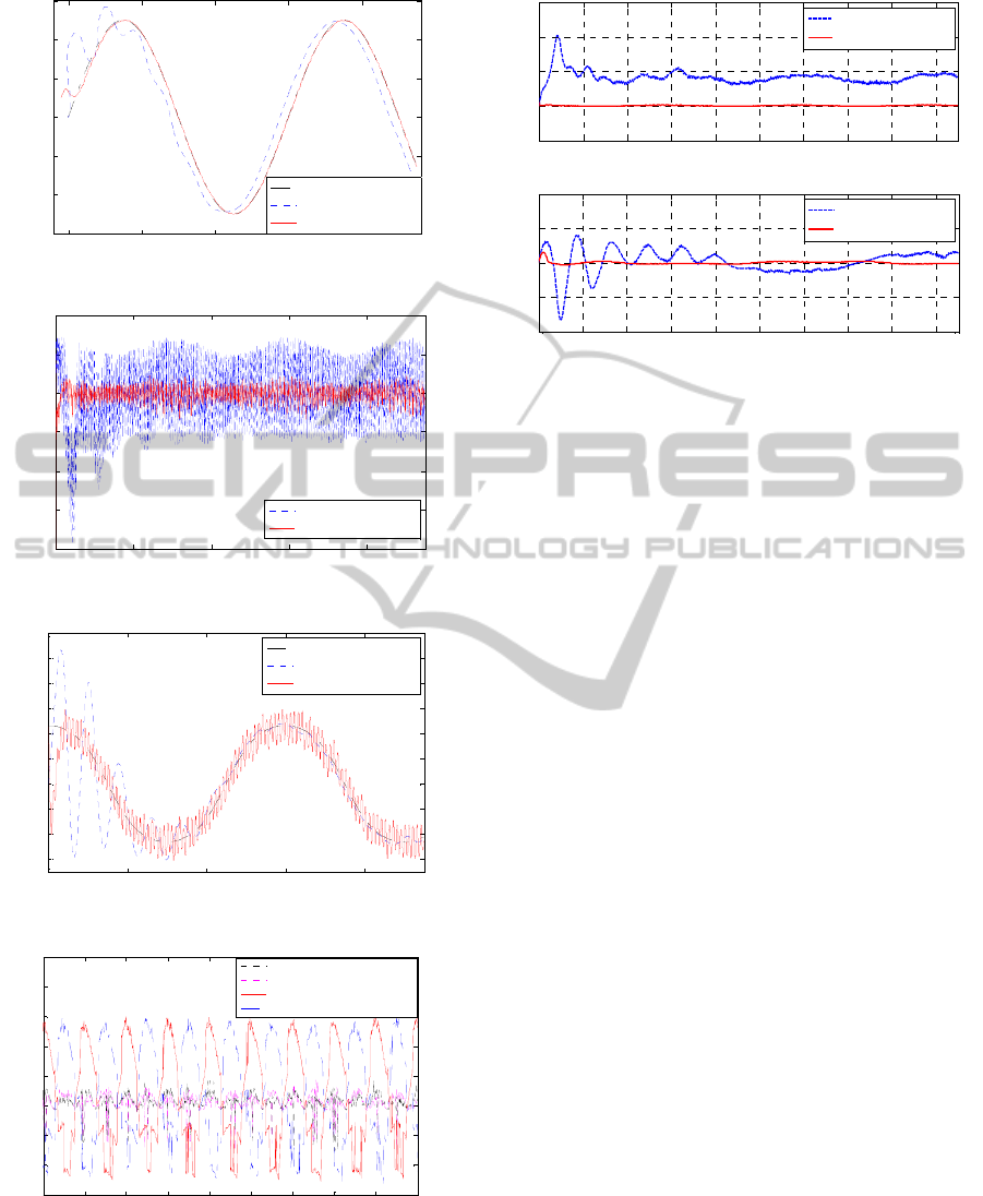
motion. Figure 6(a) and 6(b) show the position
errors and the velocity errors of the platform during
the simulation time. The steady state errors have
been achieved by applying the Backstepping control.
On the other hand, the steady state error has been
reduced by integrating I-PD and backstepping
controller. From Figure 6(c), the posture angle
becomes stable after temporary wobbling motion. As
the radius of curvature is decreased, higher torque
difference has to be exerted at both sides of platform
motors. Therefore, as resulted in Figure 6(d), the
ICINCO2015-12thInternationalConferenceonInformaticsinControl,AutomationandRobotics
378
(a)
(b)
(c)
(d)
Figure 6: Simulation results with a curved line trajectory
tracking, (a) Trajectory, (b) Error in velocity, (c) Posture
angle, and (d) Input motor torque.
Figure 7: Error comparison in the curved line trajectory
tracking.
torque difference at each motor can be generated by
exerting resistive torques to create yaw moment of
the platform. Figure 7 compares position errors of
backstepping controller with integrated I-PD
controller with backstepping.
4 CONCLUSIONS
A new controller that enables stable trajectory
tracking of an autonomous mobile platform for duct
cleaning has been presented. Four-wheeled skid
steering platform can be confronted by the
singularity problem during pivot turning where the
velocity at CM of the platform approaches zero. In
particular, shifting CM by reciprocating the brush-
arm periodically makes the steering moment of the
platform change. To avoid singularity problem
backstepping technique has been adopted for
assigning the estimated target velocity. Nevertheless,
under dynamic pressure changes in the brush arm,
there existed steady state errors which can not be
ignored. Therefore, by integrating a relatively simple
I-PD controller with the backstepping, the overall
position errors could be reduced, which enables
stable trajectory tracking control under variable CM.
ACKNOWLEDGEMENTS
This research was carried out as a part of project
partially funded by the Ministry of Land,
Infrastructure and Transport and Ministry of
Science, ICT and Future Planning in Korea.
0 1 2 3 4
-0.4
-0.2
0
0.2
0.4
0.6
X [m]
Y[m]
Reference
Backstepping
Backstepping+I-PD
0 20 40 60 80
-0.2
-0.15
-0.1
-0.05
0
0.05
Time [sec]
Velocity Error [m/s]
Backstepping
Backstepping+I-PD
0 20 40 60 80
-60
-40
-20
0
20
40
60
80
100
120
Time [sec]
Heading angle[deg]
Reference
Backstepping
Backstepping+I-PD
86 87 88 89 90 91 92 93 94 95
-4
-2
0
2
4
6
8
10
12
Time [sec]
Motor Torque [Nm]
Backstepping:Motor(L)
Backstepping:Motor(R)
Backsteppi ng+I-PD:Motor(L)
Backsteppi ng+I-PD:Motor(R)
0 10 20 30 40 50 60 70 80 90
-0.1
0
0.1
0.2
0.3
Time [sec]
Error X [m]
0 10 20 30 40 50 60 70 80 90
-0.2
-0.1
0
0.1
0.2
Time [sec]
E
rror
Y
[
m
]
Backstepping
Backstepping+I-PD
Backstepping
Backstepping+I-PD
ATrajectoryTrackingControlofaSkidSteeredMobileCleaningRobot
379

REFERENCES
Holopainen, R., Asikainen, V., Tuomainen, M., Bjorkroth,
M., Pasanen, P., Seppanen, O., 2003. Effectiveness of
duct cleaning methods on newly installed duct
surfaces.
Indoor Air. Vol. 13: pp.212-222.
Jeon, S., Jeong, W., Park, D., 2013. Surface Cleaning
Force Control of Rotating Brushes For an Air Duct
Cleaning Robot,
International Conference on
Informatics in Control, Automation and Robotics
(ICINCO), 2013 July 29-31; Reykjavik, Iceland. pp.
453-457.SCITEPRESS.
Caracciolo, L., De Luca, A., Iannitti, S., 1999. Trajectory
Tracking Control of a Four-Wheel Differentially
Driven Mobile Robot.
IEEE International Conference
on Robotics and Automation. 1999 May 10-15; Detroit,
MI. pp. 2632-2638.
Fierro, R., Lewis, F. L., 1997. Control of a Nonholonomic
Mobile Robot: Backstepping Kinematics into
Dynamics.
Journal of Robotic Systems. Vol. 14, No. 3,
pp. 149-163.
Jeong, W., 2014. Performance Analysis of a Mobile Duct
Cleaning Robot.
International Journal of Advanced
Engineering Applications.
Vol. 7, No. 2, pp. 26-32.
Kim, S., Jung, S., 2006. Hardware Implementation of a
Neural Network Controller with an MCU and an
FPGA for Nonlinear Systems.
International Journal of
Control, Automation, and Systems
. Vol. 4, No. 5, pp.
567-574.
Martinez, J. L., Mandow, A., Morales, A., Pedraza, S.,
Garcia-Cerezo, A., 2005. Approximating Kinematics
for Tracked Mobile Robots.
The International Journal
of Robotics Research.
Vol. 24, No. 10, pp. 867-878.
King, M., 2010.
Process Control: A Practical Approach.
West Sussex: John Wiley and Son. pp. 36-50.
Bloch, A. M., Reyhanoglu, M., McClamroch, N. H., 1992.
Control and stabilization of nonholonomic dynamic
systems.
IEEE Trans. Autom. Control. Vol. 37, No. 11,
pp. 1746-1757.
Sarkar, N., Yun, X., Kumar, V., 1994. Control of
mechanical systems with rolling constraints:
Application to dynamic control of mobile robots
. Int. J.
Rob. Res
. Vol. 13, No. 1, pp. 55-69.
Yang, J. M., Kim, J. H., 1999. Sliding Mode Control for
Trajectory Tracking of Nonholonomic Wheeled
Mobile Robots.
IEEE Transactions on Robotics and
Automation.
Vol. 15, No. 3, pp. 578-587.
Kanayama, Y., Kimura, Y., Miyazaki, F., Noguchi, T.,
1990. A stable tracking control method for an
autonomous mobile robot.
IEEE International
Conference on Robotics and Automation
, 1990 May
13-18; Cincinnati, OH
. pp. 384-389.
M’Closkey, R. T., Murray, R. M., 1994. Extending
exponential stabilizers for nonholonomic systems from
kinematic controllers to dynamic controllers.
Proc.
IFAC Symp. Rob. Control,1994; Capri, Italy
. pp. 211-
216.
ICINCO2015-12thInternationalConferenceonInformaticsinControl,AutomationandRobotics
380
