
Performance and Comparative Analysis of Design Schemes for
Prioritised Data in Multi-hop Wireless Mesh Backbone Networks
Sajid M. Sheikh, Riaan Wolhuter and G. J. van Rooyen
Department of Electrical and Electronic Engineering, University of Stellenbosch,
Private Bag X1, Matieland, 7602, South Africa
Keywords: DiffServ, EDCA, Fairness, IntServ, MAC, QoS, Routing, Smart Grid, Wireless Mesh Networks.
Abstract: The contention based carrier sense multiple access with collision avoidance (CSMA/CA) was originally
designed for single-hop networks. For CSMA/CA to be used in multi-hop distributed networks and to
provide guaranteed data priority, the CSMA/CA needs to be optimised. An application is the smart grid
consisting of different network domains with data of different priority levels. The IEEE802.11e standard
was developed to provide differentiated data services. With the default enhanced distributed channel access
(EDCA) settings for QoS, an unfairness problem exists for different data classes where higher priority data
can starve lower priority data and also where bandwidth is allocated unfairly. In this paper, we carry out an
investigation of six design schemes for wireless backbone networks for QoS provisioning of different data
priority classes. The design schemes are based on the concept of low-cost design for suitability in rural areas
where cost plays a major role. The simulation results were obtained using OMNET++ and the INET
framework. The performance metrics used for the analysis were end-to-end latency, packet loss percentage
and Jain’s fairness index. Simulation results show that hybrid network designs using distributed
coordination function (DCF) and EDCA can improve QoS in terms of reliability and fairness.
1 INTRODUCTION
Wireless Mesh Networks (WMNs) have gained
increasing popularity and use in recent years. This
comes due to the characteristics of WMNs that
include self organisation, auto configuration and low
cost to extend network coverage. With WMNs,
many challenges are also experienced such as
network capacity analysis, QoS routing, link-layer
resource allocation, network security, and seamless
roaming (Jiang et al., 2006). Much research has been
done and published in various areas of WMNs
which includes routing metrics, optimum routing,
security, scheduling, cross layer designs and
physical layer techniques. The capacity of WMNs is
affected by many factors such as network
architecture, network topology, traffic patterns,
network node density, number of channels used for
each node, transmission power level and node
mobility (Akyildiz et al., 2005).
Currently there are two main categories of MAC
scheduling, namely contention based and contention
free strategies. Carrier sense multiple access with
collision avoidance (CSMA/CA) is a popular
contention based scheme deployed in wireless local
area networks (WLANs) and ad-hoc networks. The
original CSMA/CA cannot perform well in wireless
multi-hop environments and offers poor throughput
performance and unfairness problems (Jiang et al.,
2006). Although IEE802.11 and IEEE 802.11e work
well in single hop networks, they present significant
challenges when used in ad-hoc networks such as
collision problems, throughput degradation and the
collision window being increased significantly with
an increase in collision and hence increasing the
end-to-end delay (Yeh, 2004).
The distributed coordination function (DCF) in
the IEEE 802.11 standard does not provide data
priority. The IEEE 802.11e standard was developed
to provide service differentiation using the enhanced
distributed channel access (EDCA). For the different
access categories (AC) or data classes, different
arbitration interframe spacing (AIFS), different
minimum and maximum contention window (CW)
sizes parameters are used in the backoff procedure
for service differentiation. High priority traffic gets
assigned smaller AIFS and CW values compared to
lower priority data classes. This gives the higher
priority AC a higher chance to access the channel
first compared to the lower AC. EDCA can only
13
Sheikh S., Wolhuter R. and Rooyen G..
Performance and Comparative Analysis of Design Schemes for Prioritised Data in Multi-hop Wireless Mesh Backbone Networks.
DOI: 10.5220/0005567300130023
In Proceedings of the 12th International Conference on Wireless Information Networks and Systems (WINSYS-2015), pages 13-23
ISBN: 978-989-758-119-9
Copyright
c
2015 SCITEPRESS (Science and Technology Publications, Lda.)

provide increased statistical chances rather than
guaranteed prioritised access to higher priority
traffic (Jiang et al., 2006).
For companies to setup wireless telemetry
networks in rural areas such as for micro-grids or to
extend the smart grid, particularly in Africa, the rate
of return of their investment plays a major role as
the population size is smaller and the standard of
living is lower compared to urban areas with a high
percentage of low income people (Sargunarangan,
2011)(Monitor, 2012). Therefore, in rural areas,
WMNs may be more feasible as a more cost
effective solution compared to other solutions such
as fiber optic, cellular networks, WiMax or VSATs.
A typical use case for WMNs viewed in this paper is
the smart grid. The smart grid is comprised of many
network domains that have to be interconnected to
provide end-to-end services. Data in these different
rural smart grid domains need to be given different
priorities depending on the application domain, such
as smart meter data, data from management or
control domains or monitoring domains (Jeon,
2011).
We investigate six design schemes for the
wireless backbone mesh networks based on the
objective of determining high performance, low cost
design implementations. The idea of investigating
different rules assigned to edge and core routers has
been taken from wired networks that provide
differentiated services using Integrated Services
(InterServ) and Differentiated Services (DiffServ).
The edge routers perform most of the complex
operations and the core routers perform simple
operations. In our investigations, schemes 1, 2 and 3
are based on single radio devices using a single
channel in the complete network. In schemes 4, 5
and 6, the core devices use single radios, while the
edge devices use two radios with two channels. Two
radios are only used in a few devices (edge devices)
to keep cost of implementation low. Hardware that
operate in the unlicensed Industrial, Scientific and
Medical (ISM) band can also provide lower cost as
compared to the use of licensed spectrum. In scheme
1, both the edge and core routers are configured with
the default IEEE802.11e EDCA. In scheme 2, the
edge routers are configured with the default
IEEE802.11e EDCA and the core routers are
configured with DCF CSMA/CA. In scheme 3, the
edge routers are configured with DCF and the core
routers are configured with EDCA. Scheme 4 is
identical with scheme 1, scheme 5 is identical to
scheme 2, and scheme 6 is identical to scheme 3
except that the edge routers use two radios and 2
channels in these designs.
The rest of this paper is organized as follows. In
section 2, a brief background on the smart grid
requirements is presented. In section 3, the
objectives of this research are presented. Section 4
presents a brief overview of some current priority
provisioning techniques. Related work is presented
in section 5. Section 6 presents an overview of the
proposed design schemes. Section 7 presents the
simulation experimental setup details. The
performance results are presented in section 8 for the
proposed design schemes.
2 BACKGROUND
In developed countries, a high percentage of people
are connected to the internet, while in developing
countries in Africa, the case is different. A
significant percentage of people in developing
countries in Africa, particularly in rural areas, are
living without internet. Most of the internet
subscribers in developing countries in Sub-Saharan
Africa are in urban areas. This leaves rural areas in
Africa, particularly Sub-Saharan Africa, mostly
without any internet connectivity (Johnson, 2013).
This creates a digital divide. The internet bandwidth
in rural areas is also very limited due to cost (Argaez
2014) (Johnson et al., 2012). The challenges faced
by rural communities include the lack of
communication infrastructure due to cost to provide
this infrastructure (Johnson et al., 2012) (ITU,
2014).
In most cases, a rural village in Africa is up to a
thousand kilometres away from urban areas and
villages are also widely scattered and separated
(Johnson 2013). The cost of covering this distance to
reach scattered rural villages is very high. As a
result, many rural deployments rely on expensive
satellite links (usually VSATs or cellular networks)
to provide internet access (i Direct n.d.) (Hammond
and Paul, 2006).
In rural areas, lower cost and cost effective
wireless communication based on WMNs may be
more feasible. The settlements in these villages are
usually scattered and found in clusters. The
backbone network can be extended and inter-
connected in a wireless mesh method to service
these clusters or connect these local power
generation sources. Wireless backhaul mesh
networks reduce deployment cost and extend
network coverage. The existence of multiple routes
between source and destination nodes ensures high
network availability when node or link failures occur
or when channel conditions are poor (Madihian,
2007).
WINSYS2015-InternationalConferenceonWirelessInformationNetworksandSystems
14

Table 1: Smart grid communication requirements.
Priority
Category
End-to-end
Latency
Applications Reliability
HIGH < 500ms Emergency Response, Fault
Detection, SCADA, Operations
Data
99-99.9%
MEDIUM 500ms - 2s Automated Demand Response
(ADR), Direct Load Control,
Transformer Monitoring, Outage
Management
99-99.9%
LOW 2s - 5s Advanced Metering Infrastructure
(AMI), Real Time Pricing, Voltage
and Current Monitoring, Remote
connect/Disconnect
99-99.9%
For this study, the requirements of a smart grid
communication network are considered. The data
services have been grouped into three priority levels
i.e. high, medium and low. For WMNs to be used in
the smart grid, it will be expected to provide the
required QoS as summarised in table 1. The network
must be very reliable and provide end-to-end latency
in communication within the tolerated ranges. These
requirements are the same in both urban and rural
networks. The advanced smart metering
infrastructure can tolerate more delay than network
data from fault detection networks. Detailed smart
grid performance requirements in terms of latency
and reliability for different smart grid applications
are also stated in (Gungor, 2011) and (Jeon, 2011).
3 OBJECTIVES OF THE STUDY
Many networks carry data of different priority data,
require the network to be very reliable and provide
end-to-end latency within the tolerated ranges. In
this paper, WMNs are investigated to provide low
cost backbone connectivity for networks carrying
data of different priority such as for the smart grid in
rural areas as highlighted in section 2.
The objectives of this study are:
• To conduct performance measures for edge
and core routers in different EDCA network
design schemes to provide QoS service level
differentiation.
• To improve the overall network reliability in
a wireless multi-hop mesh network through
hybrid network designs.
• To investigate how CSMA/CA can be
configured to give optimum performance in
multi-hop wireless mesh backbones.
4 PRIORITY PROVISIONING
TECHNIQUES
4.1 Integrated and Differentiated
Services
In wired networks, QoS provisioning is carried out
using Integrated Services (InterServ) and
Differentiated Services (DiffServ). The edge routers
perform most of the complex operations and the core
routers perform simple operations.
IntServ provides services on a per flow basis.
IntServ has three main traffic classes namely, best
effort service, controlled load service and guaranteed
service. The best effort services are characterized by
an absence of a QoS specification and the network
delivers the best quality possible. In the guaranteed
services classes, users are provided with an assured
amount of bandwidth and end-to-end delay. In the
controlled load services class, users get serviced as
close as possible to the one received by a best-effort
service in a lightly loaded network (Mahadevan and
Sivalingam, 1999). With the IntServ, QoS support
mechanisms at the network elements can be
provided by various packet classifying and
scheduling mechanisms such as Class Based
Queuing (CBQ) and Weighted Fair Queuing (WFQ).
The signalling of the flow requirements is done
using the Reservation Protocol (RSVP). The RSVP
protocol carries the QoS parameters from the sender
to the receiver to make resource reservations along
the path (Mahadevan and Sivalingam, 1999).
For DiffServ, flows are aggregated into classes
and are treated according to their class, while
IntServ provides per-flow guarantees. Diffserv does
not need to book resources in advance as compared
to IntServ. DiffServ performs mapping multiple
flows into a few service levels. The 8-bit TOS (Type
of Service) field in the IP header is included to
support packet classification. The TOS byte is
divided into 6 bit Differentiated Services Code Point
(DSCP) field and a 2-bit unused field (Mahadevan
and Sivalingam, 1999). The edge router operates in a
wired system using DiffServ included in packet
classification, packet marking and traffic
conditioning. The core router functions using
DiffServ include packet forwarding based on the
per-hop behavior (PHB) that is associated with the
packet class. DiffServ provides QoS services by
differentiating between service classes. Every class
gets a different Behaviour Aggregate (BA). A BA is
a collection of packets with the same DSCP crossing
a router node in a particular direction. Packets are
PerformanceandComparativeAnalysisofDesignSchemesforPrioritisedDatainMulti-hopWirelessMeshBackbone
Networks
15
forwarded according to the Per-Hop-Behaviour
(PHB) associated with the DSCP (Bos, 2007). The
edge routers in the network perform the complicated
functions such as traffic classification and
conditioning, and the core network is kept simple
(without per-flow information), which makes
DiffServ scalable (Jiang et al., 2006). Diffserv
provide specific treatment known as per-hop
treatment depending on the class of the packet.
4.2 Enhanced Distributed Channel
Access (EDCA)
In wireless networks, QoS is provided using EDCA
for contention based CSMA/CA. The DCF operates
on a listen before talk principle known as
CSMA/CA. In the DCF mode, if a node has data to
transmit, it first senses the medium before
transmission. If the medium is sensed to be idle for a
time period known as DCF interframe space (DIFS),
the station then performs a backoff procedure where
a slotted backoff time is generated randomly from a
contention window (CW). After this period, if the
medium is found idle, transmission takes place.
If the medium is sensed to be busy, the station
then waits for the channel to become idle for the
DIFS period and then the backoff procedure is
started again. At the first transmission attempt, the
CW is set to the minimum value, CW
min
. For any
unsuccessful transmission, this value is doubled.
When the contention window reaches its maximum
size of 1023, it stays constant until it can be reset to
CW
min
after the successful transmission.
Many networking applications require
differentiated services. This can be done by giving
higher priority data preferential access to the
medium. The IEEE 802.11e standard has been
developed to provide differentiated services for QoS
provisioning. It specifies the use of EDCA and
hybrid coordination function (HCF) (Kaveh
Pahlavan, 2002). EDCA is an extension of DCF and
introduces the concept of access category (AC) for
data types. Data is mapped at the MAC layer into the
corresponding AC. The four access categories are
background (BK), best-effort (BE), video (VI) and
voice (VO). EDCA introduces a new interframe
spacing called Arbitration IFS (AIFS). For each of
the ACs, the corresponding CW values are shown in
table 2.
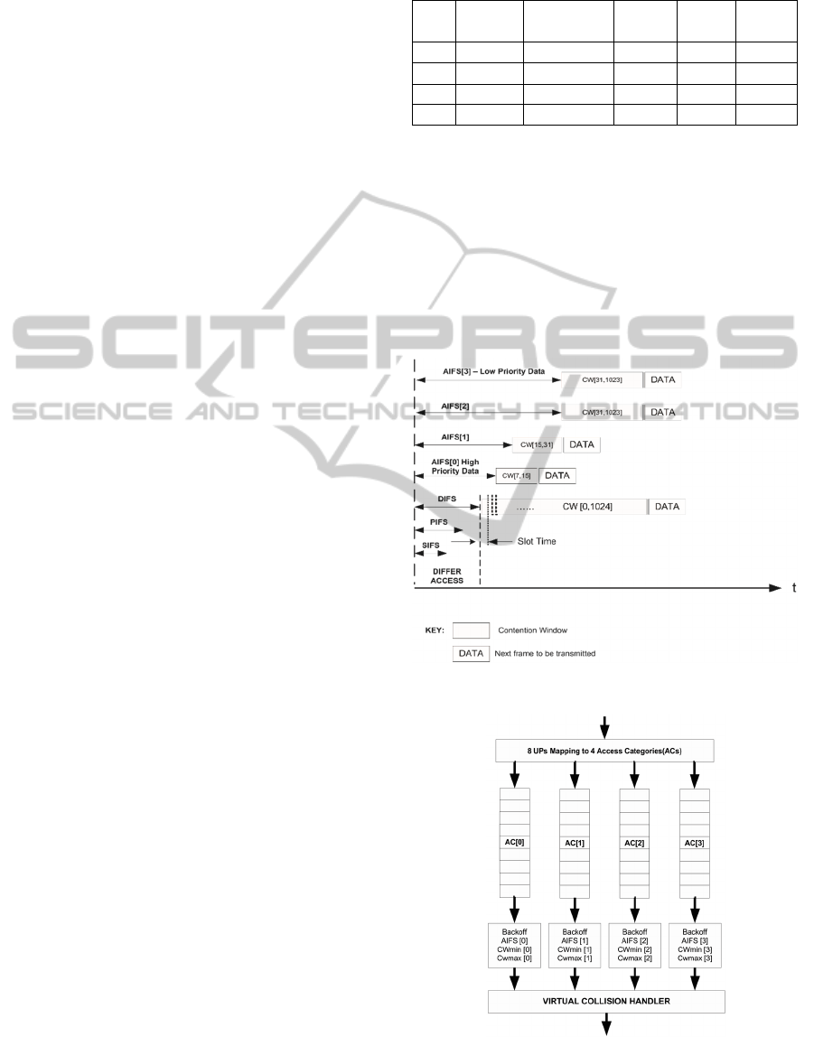
Figure 1 illustrates the different AC’s, AIFS and
parallel backoff entities in EDCA in a timing
diagram. AC[0] has the shortest AIFS period and
back off range, compared to the lower priority data.
Figure 2 shows the implementation scheduling
Table 2: Parameters of EDCA assigned to each AC
category.
AC AC Type Traffic Type AIFSN CW
min
CW
max
AC[3] AC_BK Background 7 31 1023
AC[2] AC_BE Best Effort 3 31 1023
AC[1] AC_VI Video 2 15 31
AC[0] AC_VO Voice 2 7 15
structure of EDCA. If any queue has data, data is
scheduled after sensing the medium to be idle for the
AIFS period and CW backoff depending on the
priority class. If data from two ACs finish the AIFS
period and CW back off period, an internal collision
takes place. The internal collision is handled by the
virtual collision handler, where the higher priority
data is allowed to transmit and the lower priority
data has to contend for the medium again behaving
as if a collision on the medium as occurred.
Figure 1: EDCA timing diagram.
Figure 2: Reference EDCA implementation model for
IEEE802.11e.
WINSYS2015-InternationalConferenceonWirelessInformationNetworksandSystems
16

EDCA is characterised by inherent short-term
unfairness (Jiang et al. 2006). One of the reasons for
this unfairness is that when a node transmits
successfully, it sets its CW to the CW
min
, giving its
remaining packets a better chance to be transmitted
before packets from other nodes with a larger CW
(Jiang et al., 2006).
5 RELATED WORK
The fairness problem in IEEE 802.11e has been
mainly addressed in literature using weighted queue
techniques as in (Farn and Chang, 2005), adjusting
CW values as in (Kuppa and Prakash, 2004), fair
queuing as in (Somani and Zhou, 2003) and
(Abuzanat et al. 2009) or adaptive queuing as in
(Hammouri and Daigle, 2011). Very little research
has been conducted in tackling the unfairness and
performance issues presented in EDCA from a
design aspect.
In (Kang, 2006), a differentiated services (DS)
model using IEEE 802.11e in wireless access
networks is proposed. In their design, the wireless
users are able to send and receive RSVP messages.
The wireless access point (WAP) is configured to
carry out IEEE 802.11e service differentiation, carry
RSVP signals and mark packets for service
differentiation in the core. This scheme was
designed mainly for a hybrid model of a wired and
wireless network to provide an end-to-end QoS
guarantee between mobile users over the wireless
access networks.
The novel contributions of this work are that we
introduce a design scheme that differentiates the
roles of edge and core routers. The core routers are
designed to perform simple tasks such as packet
forwarding based on channel contention detection,
while the edge routers are designed to perform more
complex tasks such as data classification and
statistically scheduling data according to the priority
class.
6 PROPOSED DESIGN SCHEMES
In this research, we propose and investigate six
design schemes for the wireless backbone network.
In the proposed schemes we assume a hierarchical
backbone mesh network structure consisting of edge
and core routers. User clients can connect to the
edge routers, while the core routers connect to the
backbone routers and carry the data in the backbone.
Figure 3 shows the six design concepts used in our
investigation.
The schemes are based on the concept of low cost
design implementation solutions and hence we
investigate designs 1, 2 and 3 for single radio and
single channel for both edge and core devices.
Schemes 4, 5 and 6 are the same designs as schemes
1, 2 and 3, with the addition of an additional radio in
the edge nodes and an additional channel. In
schemes 1, 2 and 3, omni-directional antennas are
used. In schemes 4, 5 and 6, omni-directional
antennas are used, with 1 radio in the edge devices
connecting the user devices and the other antenna
connecting the backbone devices. Non-overlapping
channels are used.
In schemes 1 and 4, EDCA is configured in both
the edge and core routers. In schemes 2 and 5, DCF
is configured in the core routers and EDCA is
configured in the edge routers. In schemes 3 and 6,
EDCA is configured in the core routers and DCF is
configured in the edge routers.
7 SIMULATION ENVIRONMENT
To investigate our design concepts, simulations were
set up in OMNET++ using the INET framework.
OMNET++ is an open source application. The INET
framework offers detailed modelling of radio
propagation, interference estimation, implementation
of various MAC, network layer, and transport and
application layer protocols of wireless network
(Ganlenbein, 2010). Table 3 gives details of the
simulation setup implemented in OMNET++ using
the INET framework. In our designs, we assume no
capture effects, and no hidden terminal or exposed
terminal problems. Simulations were carried out on
different network sizes. The maximum network size
for the backbone mesh used in the simulations was
36, as in real life deployments a network using this
many nodes can cover a comparatively large area in
outdoor applications. The standard IEEE802.11e
model with AC[0] for high priority data, AC[1] for
medium priority data and AC[2] for low priority
data was used. The traffic type was heterogeneous
with different priority levels.
For each of the 6 design schemes, 3 experiments
were carried out on different network topology sizes
(3x3, 4x4 and 5x5). Therefore, a total of 18
experiments were carried to obtain the results for the
performance analysis. The experiments were each
repeated twice to verify the results. The confidence
interval was 95%.
PerformanceandComparativeAnalysisofDesignSchemesforPrioritisedDatainMulti-hopWirelessMeshBackbone
Networks
17

Figure 3: Proposed design schemes for the wireless backbone mesh network.
Table 3: Simulation Environment.
Network Setup
Simulation Time 300 seconds
Topologies type: Grid Topology
Number of Nodes 16, 25 and 36 for the backbone
Mesh Sizes for Backbone nodes 4x4, 5x5, 6x6
Backbone separation Distance 300m between nodes
Area 2.2km x 2.2km = 4.84km
2
Propagation Model Free Space Model
Carrier Frequency 2.4GHz
Data rate 54Mbits/s
Application Data UDP Basic Burst Packets
Data Categories
3 categories of Data - Low, Medium
and High Priority
Packet Size 512bytes
Rate of Transmission 100 packets/second
User Data Protocol (UDP) data was used in our
simulations for the three types of priority data. UDP
does not establish connections between the source
and destinations (connectionless) and also there are
no retransmission of lost packets (Xylomenos and
Polyzos, 1999). The use of UDP packets help
determine the reliability of the network through
packet loss measures. On the other hand,
Transmission Control Protocol (TCP) is connection
oriented and also feedback is received for delivered
packets (Xylomenos and Polyzos, 1999).
To test the possibility of nodes dropping packets
and also higher priority data starving lower priority
data, the arrival data rate for all the data classes was
set to 100 packets/sec. In many real life situations,
the end devices are usually randomly distributed
which gain access to the network by connecting to
the backbone devices. In rural settings in Africa, it is
possible to layout backbone grid topologies or
topologies that are close to grid topology due to
large open areas as mentioned briefly in section 2.
Grid topologies provide a high number of mesh links
and hence increase the reliability when some node
connections are lost.
To assess the performance of our proposed
design schemes and carry out the comparative
analysis, end-to-end latency, packet loss (%) and
Jain’s Fairness Index metrics were used:
1. End-to-end latency: This is the average time
taken by a data packet to arrive at the destination
from the source. It includes all the delay experienced
from the source to the destination which includes
WINSYS2015-InternationalConferenceonWirelessInformationNetworksandSystems
18

route discovery processes, data queuing and packet
transmission. Only the data packets successfully
delivered to the destinations are used in these
calculations (Vardakas et al., 2007).
2. Packet Loss: This is the measure of the
percentage of packets lost from the source to the
destination. This value was measured at the
destination as (Periyasamy, 2014):
PacketLoss
%
=
∗
(1)
Where
is the number of packets is transmitted
and
is the number of packets received.
3. Jain Fairness Index (JFI): A fairness index is
a measure of how fair or unfair the resources are
shared among the competing hosts. Equation 2 is
used to calculate fairness where x
i
is the normalized
throughput of station i, and n is the number of flows
in the WMN. A JFI of 1 indicates absolute fairness
and a JFI of 0 absolute unfair resource distribution
(Deng and Han, 2009). In our case n=3 as we
investigate the fairness for 3 data classes namely for
high, medium and low priority classes.
,
,
,….,
=
∑
∑
(2)
ℎ0 ≤
,
,
,….,
≤1
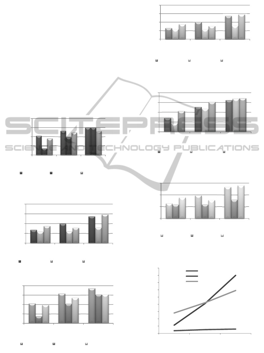
8 RESULTS
The performance of the six schemes were analysed
in terms of packet loss in figures 4 to 9. Figure 4
displays the packet loss for high priority data in
schemes 1, 2 and 3. Scheme 2 experienced the least
packet loss for high priority data in a 4 by 4 network
and 5 by 5 network. Scheme 3 experienced the least
packet loss in a 6 by 6 network for high priority
data. For high priority data in schemes 4, 5 and 6 as
can be seen in figure 5, scheme 5 experienced the
least packet loss. Figure 6 displays the packet loss
for medium priority data in schemes 1, 2 and 3.
Scheme 2 experienced the least packet loss for
medium priority data in all investigated topology
sizes. For medium priority data in schemes 4, 5 and
6 as can be seen in figure 7, scheme 5 experienced
the least packet loss. Figure 8 displays the packet
loss for low priority data in schemes 1, 2 and 3.
Scheme 2 experienced the least packet loss for low
priority data in 4 by 4 and 5 by 5 topologies. Scheme
1 experienced the least packet loss in the 6 by 6
topology. For low priority data in schemes 4, 5 and 6
as can be seen in figure 9, scheme 5 experienced the
least packet loss. Overall, in the single radio and
single channel schemes (schemes 1, 2 and 3),
scheme 2 which uses DCF in the core routers and
EDCA in the edge routers performed the best. In the
two radio and two channel schemes (schemes 4, 5
and 5), scheme 5 which uses DCF in the core routers
and EDCA in the edge routers performed the best in
terms of least packet loss. For both schemes 2 and 5,
DCF is configured in the core routers and EDCA in
the edge routers. DCF is the core routers gives all
packets carried in the core network an equal chance
of medium access and also packets are transmitted in
a first in first out (FIFO) fashion in the core network.
Doing this reduces the collision probability for high
and medium priority data. The performance in terms
of packet loss reduction improves with the addition
of the additional resources in the edge nodes as in
scheme 5. Edge routers in real life networks are
usually subjected to more traffic load and
congestion. The multi-radio and multi-channel
scheme used in scheme 5 helps lower the packet loss
considerably. Packet loss reduces in the hybrid
design of DCF in the core routers and EDCA in the
edge routers as the number of collisions is expected
to have reduced due to a larger CW range in the core
routers. DCF have larger CW ranges and contention
periods compared to the differentiated IEEE802.11e
services differentiation scheme. Higher range values
of CW with larger back off intervals reduce the
collision probability.
Figures 10 to 16 present the end-to-end latency
experienced for the six design schemes. Figure 10
shows the end-to-end latency for high priority data
in schemes 1, 2 and 3. It can be seen that high
priority data in scheme 1 experienced the least end-
to-end latency compared to schemes 2 and 3. Figure
11 shows the end-to-end latency for schemes 4, 5
and 6 for high priority data. Schemes 5 and 6 high
priority data experienced more latency compare to
scheme 4. The single channel, single radio schemes
(1, 2 and 3) experience more delay then the 2
channel and 2 radios in the edge devices (schemes 4,
5 and 6). Figure 12 shows the end-to-end latency in
schemes 1, 2 and 3 for medium priority data.
Schemes 2 and 3 medium priority data experienced a
considerable increase in latency compared to scheme
1. In figure 13 for medium priority data for schemes
4, 5 and 6, an increase in latency can be observed for
schemes 5 and 6 compared to scheme 4. In figure 14
for low priority data for schemes 1, 2 and 3, schemes
2 and 3 also experience an increase in latency
compared to scheme 1. The increase in latency for
schemes 2 and 3 for low priority data is not as much
PerformanceandComparativeAnalysisofDesignSchemesforPrioritisedDatainMulti-hopWirelessMeshBackbone
Networks
19
as that experienced for high and medium priority
data. With the hybrid design schemes with the DCF,
each priority data class are given a fixed DIFS and
CW backoff interval which results in an increase in
end-to-end latency for high and medium priority
data. It can be observed that for the cases of EDCA
configured in both edge and core routers, the latency
experienced was the least. For the schemes where
DCF was configured in the core routers and EDCA
was configured in the edge routers, a higher end-to-
end latency was experienced then the scheme with
all EDCA configured routers. The scheme where
DCF was configured in the core routers and EDCA
was configured in the edge routers, also experienced
higher end-to-end latency compared to the scheme
where EDCA was configured in the core routers and
DCF in the edge routers.
Figure 4: Packet loss for high priority data for schemes 1,
2 and 3.
Figure 5: Packet loss for high priority data for schemes 4,
5 and 6.
Figure 6: Packet loss for medium priority data for schemes
1, 2 and 3.
Figure 7: Packet loss for medium priority data for schemes
4, 5 and 6.
Figure 8: Packet loss for low priority data for schemes 1, 2
and 3.
Figure 9: Packet loss for low priority data for schemes 4, 5
and 6.
Figure 10: End-to-end latency measured for high priority
data in schemes 1, 2 and 3.
0,0
20,0
40,0
60,0
80,0
4 x 4 5x5 6x6
Packet Loss (%)
Toplogy Size
Scheme 1 Scheme 2 Scheme 3
0,0
10,0
20,0
30,0
40,0
4 x 4 5x5 6x6
Packet Loss (%)
Toplology Size
Scheme 4 Scheme 5 Scheme 6
0,0
20,0
40,0
60,0
80,0
4 x 4 5x5 6x6
Packet Loss (%)
Topology Size
Scheme 1 Scheme 2 Scheme 3
0,0
10,0
20,0
30,0
40,0
4 x 4 5x5 6x6
Packet Loss (%)
Topology Size
Scheme 4 Scheme 5 Scheme 6
0,0
20,0
40,0
60,0
80,0
4 x 4 5x5 6x6
Packet Loss (%)
Topology Size
Scheme 1 Scheme 2 Scheme 3
0,0
10,0
20,0
30,0
4 x 4 5x5 6x6
Packet Loss (%)
Toplogy Size
Scheme 4 Scheme 5 Scheme 6
0,0
10,0
20,0
30,0
40,0
50,0
60,0
70,0
80,0
90,0
4 x 4 5x5 6x6
End-to-End Latency (msec)
Topology Size
Scheme 1
Scheme 2
Scheme 3
WINSYS2015-InternationalConferenceonWirelessInformationNetworksandSystems
20
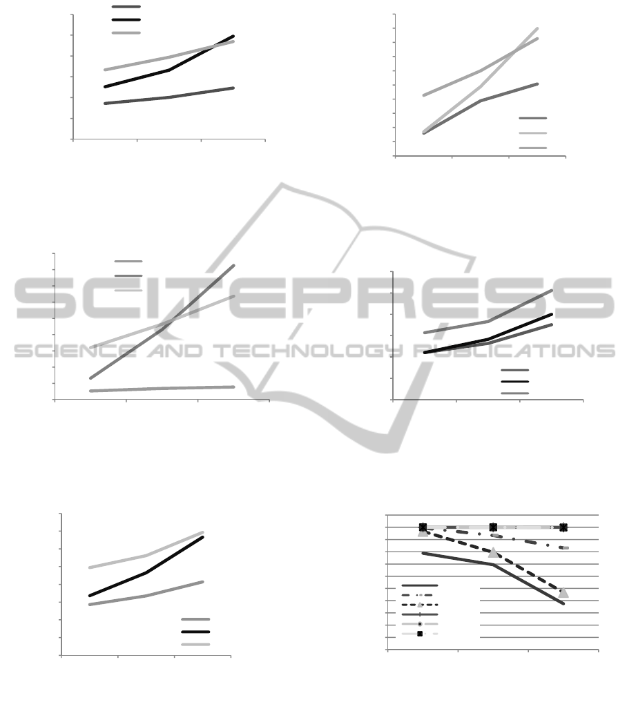
Figure 11: End-to-end latency measured for high priority
data in schemes 4, 5 and 6.
Figure 12: End-to-end latency measured for medium
priority data in schemes 1, 2 and 3.
Figure 13: End-to-end latency measured for medium
priority data in schemes 4, 5 and 6.
With the default EDCA, an unfairness problem
exists as mentioned where higher priority data can
starve lower priority data. The Jain’s fairness index
for all the six schemes is shown in figure 16. For the
single radio and single channel schemes (schemes 1,
2 and 3), scheme 2 provided the highest fairness.
Figure 14: End-to-end latency measured for low priority
data in schemes 1, 2 and 3.
Figure 15: End-to-end latency measured for low priority
data in schemes 4, 5 and 6.
Figure 16: Fairness indication of the three schemes using
Jain’s Fairness Index.
The two radios, two channels schemes configured
in the edge routers, all provided fairness of 1. The
network design in scheme 2 is shown to provide
higher fairness. Schemes 2 and 5 give an equal
chance probability to all data priority classes in the
core network which improves fairness in the
network.
0,0
1,0
2,0
3,0
4,0
5,0
6,0
4 x 4 5x5 6x6
End-to-End Latency (msec)
Topology Size
Scheme 4
Scheme 5
Scheme 6
0,0
10,0
20,0
30,0
40,0
50,0
60,0
70,0
80,0
90,0
4 x 4 5x5 6x6
End-to-End Latency (msec)
Toplogy Size
Scheme 1
Scheme 2
Scheme 3
0,0
1,0
2,0
3,0
4,0
5,0
6,0
7,0
8,0
4 x 4 5x5 6x6
End-to-End Latency (msec)
Toplogy Size
Scheme 4
Scheme 5
Scheme 6
0,0
10,0
20,0
30,0
40,0
50,0
60,0
70,0
80,0
90,0
100,0
4 x 4 5x5 6x6
End-to-End Latency (msec)
Toplogy Size
Scheme 1
Scheme 2
Scheme 3
0,0
2,0
4,0
6,0
8,0
10,0
12,0
4 x 4 5x5 6x6
End-to-End Latency (msec)
Topology Size
Scheme 4
Scheme 5
Scheme 6
0,950
0,955
0,960
0,965
0,970
0,975
0,980
0,985
0,990
0,995
1,000
1,005
4 x 4 5x5 6x6
Jain's Fairness Index
Topology Size
SCHEME 1
SCHEME 2
SCHEME 3
SCHEME 4
SCHEME 5
SCHEME 6
PerformanceandComparativeAnalysisofDesignSchemesforPrioritisedDatainMulti-hopWirelessMeshBackbone
Networks
21

9 CONCLUSIONS
In this paper the use of CSMA/CA in multi-hop
distributed backhaul networks to provide guaranteed
data priority under different design schemes was
investigated. We investigated the performance of six
design schemes for wireless backbone mesh
networks. Different roles were assigned to the edge
and core routers. Schemes 1, 2 and 3 used single
radio and single channel in core and edge routers. In
Scheme 1, all routers performed the same role and
were configured with EDCA. In Scheme 2, the edge
routers performed data classification and were
configured with EDCA. The core routers in Scheme
2 were only configured with the default DCF. In
scheme 3, DCF was configured in the edge routers
and EDCA in the core routers. Schemes 4, 5, and 6
were identical to schemes 1, 2 and 3 with the
addition of another radio in the edge routers and an
additional channel in the network.
The hybrid design scheme where DCF was
configured in the core routers and EDCA in the edge
routers experienced the least packet loss. This was
due to a reduction in the number of collisions as
DCF have larger CW ranges and contention periods
compared to the differentiated IEEE802.11e services
differentiation scheme. Higher range values of CW
with larger backoff intervals reduce the collision
probability. The different data packets carried in the
backbone devices with DCF configured have an
equal chance of gaining access to the medium and
the scheduling of packets operate as a FIFO
scheduling in the backbone devices.
The scheme with all routers configured with
EDCA in both edge and core routers, experienced
the least latency. This is as a result of the service
differentiation with higher priority data waiting less
time to access the medium. The schemes where DCF
was configured in the core routers and EDCA was
configured in the edge routers, experienced higher
delay then the EDCA scheme with all EDCA
routers. For the single radio and single channel
schemes (schemes 1, 2 and 3), scheme 2 provided
the highest fairness.
Networks that require high reliability, but can
tolerate more end-to-end latency, a hybrid design
scheme, where DCF is configured in the core routers
and EDCA is configured in edge routers will be a
good design to use. Rural smart grid networks can
be a potential application for this design scheme.
The fairness problem in IEEE802.11e in
literature has been mainly addressed using weighted
queues, adjusting CW values adaptively and
differentiated services models among others. The
novelty of this work was the improvement of
fairness from a design aspect by assigning different
roles to edge and core devices.
The objectives of the paper have been met where
DCF configured in the core routers and EDCA
configured in the edge nodes provides a hybrid
design scheme that is more reliable with less packet
loss compared to a design with EDCA configured in
all nodes. This hybrid design scheme also provides
more fairness for data of different priority. Hybrid
design schemes reduce collisions and hence result in
improved throughput.
Edge routers are subjected to more traffic load
and congestion in networks. The multi-radio and
channel scheme at the edge routers helps prevent
congestion. Further work would entail developing
fair scheduling schemes.
REFERENCES
Abuzanat, H., Trouillet, B. and Toguyeni, A., 2009. Fair
Queuing Model for EDCA to Optimize QoS in Ad-
Hoc Wireless Network. 2009 Eighth International
Conference on Networks, pp.306–311. Available at:
http://ieeexplore.ieee.org/lpdocs/epic03/wrapper.htm?
arnumber=4976692 [Accessed October 24, 2014].
Akyildiz, I.F., Wang, X. and Wang, W., 2005. Wireless
mesh networks: a survey. Computer Networks, 47(4),
pp.445–487. Available at: http://linkinghub.elsevier.
com/retrieve/pii/S1389128604003457 [Accessed May
2, 2014].
Argaez, E. de, 2014. Internet World Stats. Available at:
http://www.internetworldstats.com/stats1.htm
[Accessed April 11, 2014].
Bos, G., 2007. QoS support using DiffServ. 6th TSConIT.
Deng, J. and Han, Y.S., 2009. Fairness Index Based on
Variational Distance. Global Telecommunications
Conference, pp.1 –6.
Farn, J. and Chang, M., 2005. Proportional Fairness for
QoS Enhancement in IEEE 802.11e WLANS.
International Conference on Local Computer
Networks, (1), pp.4–5.
Ganlenbein, R., 2010. Virtual Mesh: An Emulation
Framework for Wireless Mesh Networks in Omnet++.
University of Bern.
Gungor, P.V.C., 2011. Smart Grid Communications :
Research Challenges and Oppurtunities. Presentation
at Bahcesehir Univeristy, Turkey.
Hammond, A. and Paul, J., 2006. A New Model for Rural
Connectivity. World Resouces Institure, (May).
Hammouri, M.M. and Daigle, J.N., 2011. A Distributed
Scheduling Mechanism to Improve Quality of Service
in IEEE 802. 11 Ad Hoc Networks. IEEE Symposium
on Computers and Communications (ISCC), pp.1–6.
i Direct, 8 Ways to Implementing Backhaul over Satellite
for Mobile Operators.
WINSYS2015-InternationalConferenceonWirelessInformationNetworksandSystems
22

ITU, 2014. ICTs Go Rural. Available at:
https://www.itu.int/ITU-D/ict_stories/themes/e-
rural.html [Accessed April 11, 2014].
Jeon, Y.-H., 2011. QoS Requirements for the Smart Grid
Communications Systems. International Journal of
Computer Science and Network Security, 11(3),
pp.86–94.
Jiang, H. et al., 2006. Differentiated Services for Wireless
Mesh Backbone. Communications Magazine, IEEE,
44(7), pp.113–119.
Johnson, D.L., 2013. Re-architecting Internet Access and
Wireless Networks for Rural Developing Regions.
PhD Dissertation, (March).
Johnson, D.L. et al., 2012. The Bandwidth Divide :
Obstacles to Efficient Broadband Adoption in Rural
Sub-Saharan Africa The Bandwidth Divide : Obstacles
to Efficient Broadband Adoption in Rural Sub-
Saharan Africa. , 6, pp.2467–2491. Available at:
https://www.smartgrid.gov/federal_initiatives/featured
_initiatives/usda_aims_invest_250_million_rural_sma
rt_grid_deployment.
Kang, M., 2006. Performance Analysis of An Efficient
QoS Scheme over IEEE 802. 11e Based Wireless
Access Networks. International Conference on
Advanced Communication Technology, 2, pp.929–933.
Kaveh Pahlavan, P.K., 2002. Principles of Wireless
Networks,
Kuppa, S. and Prakash, R., 2004. Service differentiation
mechanisms for IEEE 802. 11-based wireless
networks. Wireless Communications and Networking
Conference, 4, pp.796–801.
Madihian, M., 2007. Multi-hop wireless backhaul
networks: a cross-layer design paradigm. IEEE
Journal on Selected Areas in Communications, 25(4),
pp.738–748. Available at: http://ieeexplore.ieee.org/
lpdocs/epic03/wrapper.htm?arnumber=4205056.
Mahadevan, I. and Sivalingam, K.M., 1999. Quality of
Service Architectures for Wireless Networks : IntServ
and DiffServ Models. InternationalSymposium on
Parallel Architectures, Algorithms, and Networks,
pp.420 –425.
Monitor, D.S., 2012. Rural Infrastructure in Africa.
African Monitor, (1).
Periyasamy, P., 2014. Comparative Performance Analysis
of AODV and AODV-MIMC Routing Protocols for
Mobile Ad hoc Networks. International Jounal
Computer Network and Information Security, (May),
pp.54–60.
Sargunarangan, D., 2011. A Low-Cost Efficient Wireless
Architecture for Rural Network Connectivity. ACM
SIGCOMM.
Somani, A.K. and Zhou, J., 2003. Achieving Fairness in
Distributed Scheduling in Wireless Ad-Hoc Networks.
Performance, Computing, and Communications
Conference, 1, pp.95–102.
Vardakas, J.S. et al., 2007. On the End-to-End Delay
Analysis of the IEEE 802. 11 Distributed Coordination
Function. International Conference on Internet
Monitoring and Protection, pp.5–9.
Xylomenos, G. and Polyzos, G.C., 1999. TCP and UDP
Performance over a Wireless LAN. IEEE INFOCOM,
(March), pp.439–446.
Yeh, Ch.-H., 2004. A New Scheme for Effective MAC-
layer DiffServ Supports in Mobile Ad Hoc Networks
and Multihop Wireless LANs. Vehicular Technology
Conference, 4, pp.2149–2155.
PerformanceandComparativeAnalysisofDesignSchemesforPrioritisedDatainMulti-hopWirelessMeshBackbone
Networks
23
