
Issues and Challenges in Robotic Trimming of CFRP
Mohamed Slamani and Jean-François Chatelain
Department of Mechanical Engineering, École de Technologie Supérieure, Montreal, Canada
Keywords: CFRP, Trimming, Machining Errors, Robotic Machining, Robot Accuracy.
Abstract: Thanks to their adaptability, programmability, high dexterity and good maneuverability, industrial robots
offer more cutting-edge and lower-cost than machine tools to bring molded Carbon Fibre Reinforced
Polymers (CFRPs) parts to their final shapes and sizes. However, the quality of CFRP parts obtained with
robotic machining must be comparable to that obtained with a CNC machine. In addition, the robot itself
has to be very stiff and accurate to provide the same consistency and accuracy as their machine tool
counterparts. If the robot is not sufficiently stiff, chatter, overall vibrations and deviations in shape and
position of the workpieces will occur. Furthermore, during robotic machining of Carbon Fibre Reinforced
Polymer, the anisotropic and highly abrasive nature of CFRPs combined with the higher cutting forces and
the lower stiffness of the robot, lead to numerous machining problems. Therefore, robotic machining of
CFRPs stills a big challenge and need further research. In this position paper, a methodology has been
developed and implemented to identify, understand and quantify the machining errors that can alter parts
accuracy during high speed robotic trimming of CFRPs.
1 INTRODUCTION
Compared to machine tool, the industrial robot,
thanks to its adaptability, programmability, high
dexterity and good manoeuvrability, offers cutting-
edge and low cost solutions to bring the moulded
CFRP parts to their final shapes and sizes. It has
indeed already been introduced to many industrial
applications, including welding, painting and
assembly, and has produced excellent results. It is
relatively cheaper in terms of cost as compared to
the machine tool, is flexible, and has a large working
envelope. Nevertheless, current industrial robot still
cannot provide the same consistency and accuracy as
their machine tool counterparts. The most essential
sources of errors hindering the use of industrial
robots for machining applications are related to
manufacturing tolerances, joint friction, servo errors,
thermal effects, as well as flexibilities in the drives
and joints. Because of these flexibilities, the robot
end-effector will vibrate along the desired trajectory
and deflects due to the cutting forces. These
flexibilities not only limit the accuracy but also the
dynamic performance of the robot.
The successful fulfillment of manufacturing
orders requires high performance industrial robots.
However, since very limited information on robot
performance can be obtained from robot
manufacturers, its assessment in terms of accuracy
and repeatability has become increasingly important,
especially in the aerospace sector. High accuracy
trajectory performance is also a requirement in many
industrial applications, and should be provided by
the robot controller.
Many research works deal with positioning
performance in terms of type and magnitude of
typical errors. Muelaner et al. (Muelaner, 2010) used
a FARO Laser Tracker to assess the repeatability of
a large KUKA KR240 industrial serial robot and
found that it is no more than 10 micrometers, when
short periods of time are considered. The validity of
such results is, however, questionable since the
repeatability of the FARO Laser Tracker (ADM
only) itself is approximately 8 micrometers at 2 m.
To evaluate the backlash error type, which is one
of the most important source of errors affecting the
performance of industrial robots, Slamani et al.
(Slamani, 2012a) proposed an experimental
approach using a laser interferometer measurement
instrument. The effects of backlash error are
assessed statically by experiments conducted on
horizontal and vertical paths. Following statistical
analyses, they found that backlash is highly
dependent on both robot configuration and Tool
Center Point (TCP) speed, but remains nearly
unaffected by changes in payload. Ruderman et al.
400
Slamani M. and Chatelain J..
Issues and Challenges in Robotic Trimming of CFRP.
DOI: 10.5220/0005568504000405
In Proceedings of the 12th International Conference on Informatics in Control, Automation and Robotics (ICINCO-2015), pages 400-405
ISBN: 978-989-758-123-6
Copyright
c
2015 SCITEPRESS (Science and Technology Publications, Lda.)

(Ruderman, 2009) present an approach to the
modeling and identification of elastic robot joints
with hysteresis and backlash. The distributed model
parameters are identified from the experimental data
obtained from internal system signals and an
external angular encoder mounted on the second
joint of a six-axis industrial robot. However, the
static assessment technique does not consider the
real mode of operation of the robot.
We know that in many automated manufacturing
systems, higher speed is a key to productivity
enhancement. High accuracy trajectory performance
is also a requirement in many industrial robot
operations, and should be provided by the servo
mechanism. A major problem with the servo
systems of industrial robots is contour error, which
occurs during curve tracking (Slamani, 2012b,
Brogardh, 2009). A desired curve is the shortest
distance between the actual trajectory and that of the
reference command. When the robot speed is
relatively low, the contour error caused by the servo
system is usually acceptable. However, once high
speed and high accuracy are demanded, as in water
jet cutting, laser cutting, gluing, dispensing, and
deburring, for example, contour errors will have a
significant effect (Brogardh, 2009), and hence the
need to improve the performance of contouring
control by decreasing or eliminating contour errors
as much as possible. There are two commonly used
methods for achieving this. One is to design
advanced controllers, and the other is path pre-
compensation.
With respect to the control field, a large amount
of work has been done on trajectory planning,
feedback control, system compensation, and
feedforward control (Lambrechts et al. 2005,
Hakvoort et al. 2008). Koch et al. (Koch et al. 2011)
have presented an algorithm to adjust the position
and orientation of the tool by predictive vision-based
control, which compensates for system delays
caused by the robot dynamics and the vision sensor.
Dynamic errors are generally manifested in the
form of overshooting, rounding-off, and vibration
(Kataoka et al. 2011). In the case of vibration, a
well-planned trajectory guarantees good path
tracking, and generates less excitement of the
robot’s mechanical structure and servo control
system, and so this source of error can be avoided
(Olabi et al. 2010, Shimada, 95). Friction is one of
the major limitations in performing high precision
manipulation tasks, as it affects both static and
dynamic contouring performance and may cause
instability when coupled with position or force
feedback control (Lischinsky et al. 1997). Tracking
error is most likely to occur in circular arcs and
corners. When a circular arc path is ordered, the
radius of the actual path is smaller than that of the
ordered path because of a delayed servo response in
each axis. Without appropriate command system
capability and correct servo tuning, moving around a
corner at high TCP speed and acceleration actually
creates and aggravates errors.
Robotic machining has become a very important
tool in the industry. Many research studies have
been done in recent years, and have shown that
industrial robots achieve remarkable success in
many machining applications such as polishing,
grinding, deburring, and milling (Shirase et al. 1996,
Dumas et al. 2011, Leali et al. 2014). On the other
hand, precision machining applications require high
performance and precision, e.g. accuracy and
repeatability, of the industrial robot.
In the aerospace sector, the demand for lighter
aircraft components with high mechanical and
physical properties has increased the popularity of
Carbon Fibre Reinforced Polymers (CFRP). CFRP
parts are usually produced by moulding or near net
shape processing. In most applications, however,
trimming, milling, and drilling are still required to
bring CFRP parts to their final shapes and sizes. For
these machining operations, industrial robots
represent a cost-saving and flexible alternative
compared to standard machine tools. However,
during robotic machining of CFRP, the anisotropic
and highly abrasive nature of this material combined
with the higher cutting forces and the lower stiffness
of the robot, lead to high levels of vibrations. This in
turn results in numerous machining problems, such
as rapid tool wear, fibre pull-out, fibre fracture,
delamination, trajectory deviation, poor quality, and
in some cases, rejection of machined parts.
The main objectives of this work regard a better
understanding of the errors sources that can
deteriorate parts accuracy during high-speed robotic
trimming of CFRP.
2 METHODOLOGY
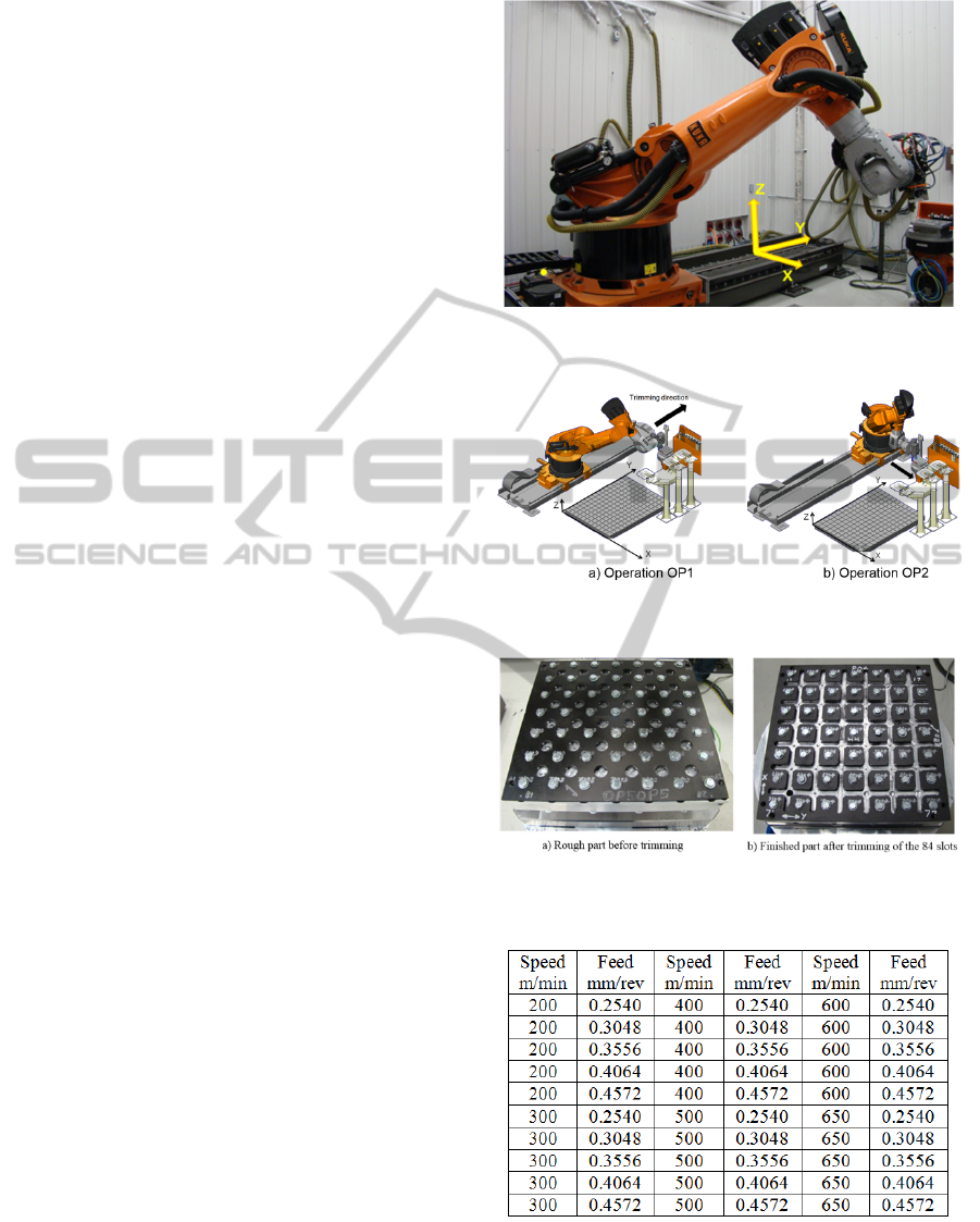
Tests were performed using a six-axis KUKA KR
500-2 MT industrial robot mounted on a 13-foot
linear rail and manipulating a heavy spindle HSD
Mechatronic ES 789 delivering spindle speeds of up
to 26000 rpm (Fig. 1). The robot could handle a
payload of 500 kg.
Because the industrial robot has heterogeneous
stiffness within its working envelope and the
compliance error is highly depending on the
IssuesandChallengesinRoboticTrimmingofCFRP
401
manipulator configuration during trimming, two
configurations (placements) were tested in this
study. The two placements were obtained by moving
the robot base on the linear axis while maintaining
the same trimming position in the two-axis
positioning table. A first placement noted “operation
OP1” with a relatively stretched configuration is
shown in Figure 2a. The trimming direction in the
OP1 is parallel to the linear axis and Y-axis of the
cell. A second placement noted “operation OP2”
with a relatively folded configuration is shown in
Figure 2b. The trimming direction of OP2 is
perpendicular to the linear axis and parallel to the X-
axis of the cell. For a given position, the distance
between the robot base and the tool is 2669 mm for
OP1 and 1816 mm for OP2.
The laminates for the machining tests were
prepared in a controlled aeronautical environment
using pre-impregnated technology. The stacks were
autoclave-cured, and the plies were oriented such as
to ensure that the laminate had quasi-isotropic
properties. The 24-ply laminate was 3.68 mm thick,
with a fibre volume fraction of 64 %.
Before starting the first trimming test, the
laminates were pre-drilled for tightening on a
machining fixture, as shown in Figure 3. The pre-
drilling was necessary for screwing the laminate to
the fixture, to facilitate the smooth entry of the cutter
in the laminate and to avoid the transient vibrations
and reached a constant TCP speed when detouring
each slot using different cutting conditions. The
aluminum back plating system (Fig. 3), which uses
49 screws and a torque wrench to secure the
laminate, was designed to trim 84 slots on two
placements of the robot (OP1 and OP2) and under
different cutting conditions. A total of 42 slots along
the Y-axis of the cell during the OP1 operation and
42 slots along the X-axis of the cell during the OP2
operation were trimmed. As shown in Table 1,
different combinations of cutting parameters were
tested for the OP1 and OP2 operations, respectively.
The subassembly (laminate and back plate) was
tightened to a three-axis Kistler 9255B type
dynamometer table. The assembly was subsequently
installed on the two-axis positioning table KUKA
DKP-400 (Fig. 1), located in the working space of
the robot. The positioning table and the linear axis
supporting the robot were static during the trimming
tests. The tool used to trim the coupons was a
3/8 inch diameter PCD end mill with two straight
flutes, having a 20° rake angle, a 10° relief angle and
a 5 μm cutting edge radius. The cutter was inspected
prior to the machining operation.
Figure 1: Photo of the six-axis KUKA KR 500-2 MT
industrial robot.
Figure 2: Robot configurations during the operation
OP1and OP2.
Figure 3: State of the part before and after trimming.
Table 1: Cutting conditions of the robotic trimming tests.
3 RESULTS AND DISCUSSION
The machinability of CFRPs in high speed robotic
ICINCO2015-12thInternationalConferenceonInformaticsinControl,AutomationandRobotics
402
end milling was evaluated via parameters such as
cutting forces, delamination, profile deviation and
dimensional error. The knowledge of the cutting
forces during robotic trimming processes is of great
importance, it is considered as the most important
indicator of machining condition. Usually, in robotic
machining this force causes essential deflections that
decrease the quality of the part.
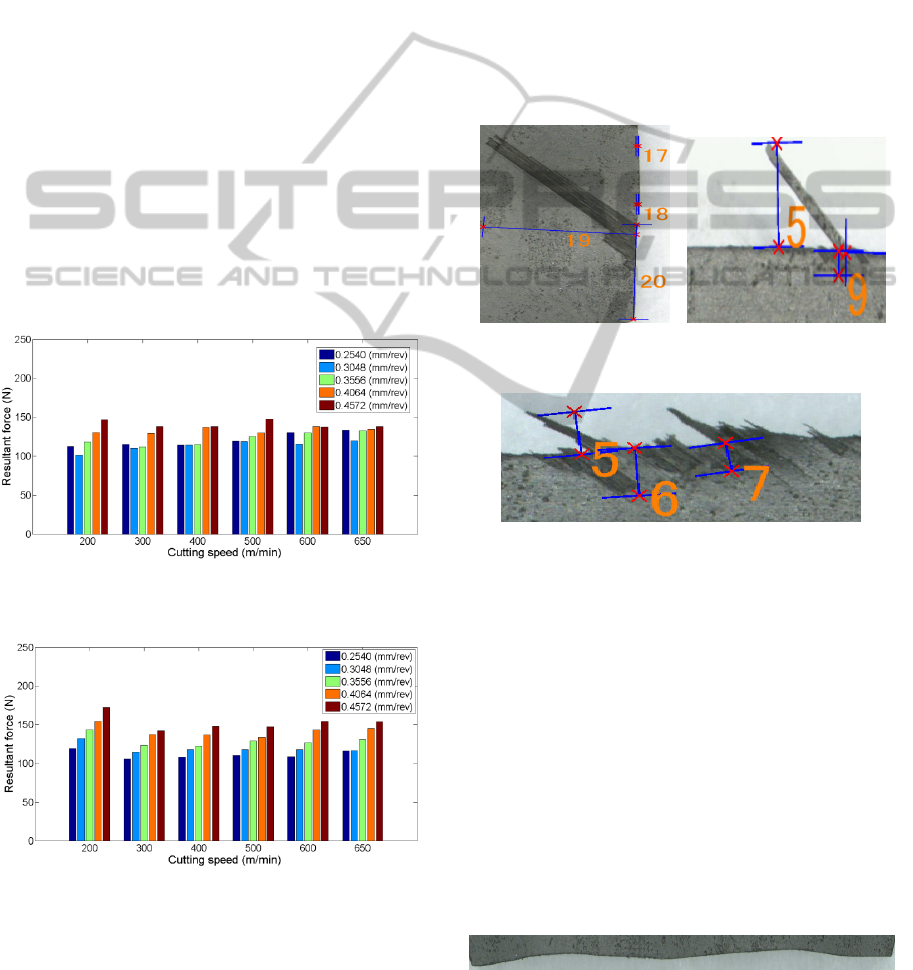
Specimens were trimmed under different cutting
conditions, and the cutting forces were measured in
the x, y, and z directions with a 3-axis dynamometer
table. The cutting force data were then recorded for
further analysis and evaluation. Figures 4 and 5
express the evolution of resultant cutting forces
versus TCP speed (feed rate) and cutting speed for
the OP1 and OP2 operations respectively. According
to these figures, it can be seen that the cutting force
increases as the TCP speed increases. This is
explained by the fact that when the TCP speed
increases, the laminate resists more to the rupture
and requires larger efforts. Hence the cutting force
increases as the TCP speed increases. On the other
hand, Figures 4 and 5 show that there is no much
effect of cutting speed on cutting force.
Figure 4: Resultant cutting force as function of cutting
speed and TCP speed for the OP1 operation.
Figure 5: Resultant cutting force as function of cutting
speed and TCP speed for the OP2 operation.
The most important type of edge surface
damages during trimming of CFRP is delamination
(Sheikh-Ahmad, 2009). This damage is caused by
the absence of support from the adjacent plies during
trimming. So the delamination is usually found on
the top and the bottom of the surface plies. Figure 6
shows the delamination of type I of the surface areas
where some ply fibers are missing. The maximum
value of delamination measured in this case was
4.8 mm (#19 in Fig. 6). Figure 7 shows the
delamination of type II where some of the uncut
fibers overhung from the trimmed edge. The value
of delamination in this case was 1.4 mm (#5 in
Fig. 7). A combination of both type I, and type II
delamination was also observed in these tests
(Fig. 8). The measured delamination values were
0.65 mm, 0.7 mm and 0.45 mm for #5, #6 and #7
respectively (Fig. 8).
Figure 6: Type I
delamination.
Figure 7: Type II
delamination.
Figure 8: Type I/II delamination.
During the trimming operations, when the robot
controller attempts to move the tool along the
nominal tool path, the actual profile usually deviates
from the programmed one. This deviation is due to
the combined effects of the robot errors and the
machining process errors. Figures 9 to 12 show
some trajectory deviations for different cutting
conditions. We can observe from these figures that
the machining error consists in material undercuts
for the whole profiles having magnitudes of
0.32 mm, 0.435 mm, 0.45 mm and 1.02 mm (Fig. 9
to 12). The figures also show that the trajectory
deviations are strongly affected by the cutting
conditions. This is shown by different wavy paths
that are clearly visible for each cutting condition.
Figure 9: Trajectory deviations for OP1 operation at TCP
speed of 0.3048 mm/rev and speed of 400 m/min.
IssuesandChallengesinRoboticTrimmingofCFRP
403
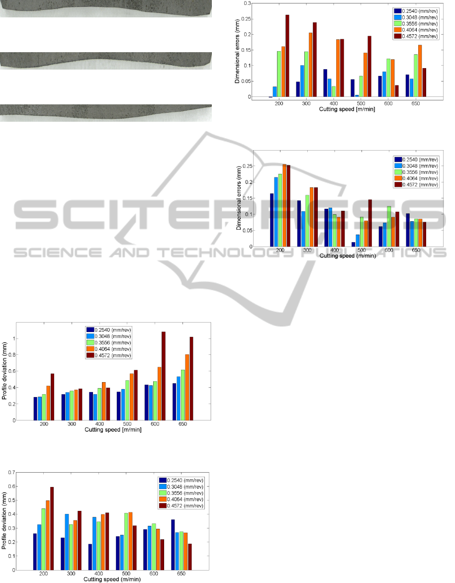
Figure 10: Trajectory deviations for OP1 operation at TCP
speed of 0.2540 mm/rev and speed of 600 m/min.
Figure 11: Trajectory deviations for OP1 operation at TCP
speed of 0.2540 mm/rev and speed of 650 m/min.
Figure 12: Trajectory deviations for OP1 operation at TCP
speed of 0.4572 mm/rev and speed of 650 m/min.
At high cutting conditions, dynamic errors
become a significant source of errors, which affect
the path accuracy. This is manifested through high
amplitude vibrations along the trimmed path. This
behaviour is explained by the variations of the
cutting force during machining and the poor rigidity
resulting from flexibility in the joints, which induces
vibrations in the end-effector. It is important to note
that the dynamic performance of an industrial robot
is even less homogeneous than its static
performance. Obviously, the less the main joints
(especially joint 1) are displaced, the better the
dynamic performance of the robot.
Figure 13: Profile error as a function of the cutting speed
and TCP speed for OP1.
Figure 14: Profile error as a function of the cutting speed
and TCP speed for OP2.
Figure 15: Dimensional error as function of the cutting
speed and TCP speed for OP1.
Figure 16: Dimensional error as function of the cutting
speed and TCP speed for OP2.
For further analysis of the machining errors, each
trimmed slot was inspected with a Mitutoyo
CRYSTA coordinate measuring machine. The
profile deviations and dimensional errors for each
cutting condition were calculated and the results are
plotted in Figures 13 to 16.
Figures 13 and 14 show the profile deviation as a
function of the cutting speed and TCP speed for the
OP1 and OP2 configurations, respectively. The
results show that the profile deviations for the OP2
(with relatively folded configuration) are much
better than for OP1. They vary from 0.3 mm to
1.15 mm and from 0.2 mm to 0.6 mm for the OP1
and OP2, configuration respectively. They also show
that generally, the profile deviations for the OP1
configuration slightly increases with an increase in
the TCP speed and cutting speed. Conversely, for
the OP2 configuration, the results show that overall;
the profile deviations increase with an increase in
the TCP speed and slightly decrease with an increase
in cutting speed.
4 CONCLUSIONS
In this paper, the sources of error in high speed
robotic trimming of CFRP are investigated. The
most important sources were identified and
ICINCO2015-12thInternationalConferenceonInformaticsinControl,AutomationandRobotics
404

quantified. In the light of the experimental results
presented, the following conclusions can be drawn:
• The cutting forces proved to be more sensitive
to the TCP speed than it is for the cutting speed;
they increased as the TCP speed increased.
• Results show that during high speed robotic
trimming, inaccuracies of the serial robot
kinematic, the mechanical compliance of the
robot and the effective process forces are
leading to large trajectory deviations which
leads to profile errors and dimensional errors.
• Results show also that trajectory deviations and
delamination are the main sources of error
affecting the accuracy of CFRP parts.
• The robot configuration, which is optimally
suited to perform the trimming task, is reached
by using a relatively folded configuration and a
minimal displacement of the joint 1.
During high-speed robotic trimming of CFRP,
the higher cutting forces and the lower stiffness of
the robot, lead to high levels of vibrations.
Regenerative vibrations create chatter. Chatter not
only limits the productivity of cutting processes, but
also causes delamination, poor surface finish,
reduces geometrical accuracy and in some cases,
rejection of machined parts. As future work, it
would be interesting to study the relationship
between cutting conditions and chatter, chatter and
delamination, chatter and tool wear and finally
chatter and surface roughness. A study on the
stability lobes for the prediction of chatter formation
could be also interesting.
On the other hand, results show that trajectory
deviations are the most sources of error affecting the
accuracy of CFRP parts. To reduce the effect of
trajectory deviations, it might be interesting to
propose compensation strategies for this error.
REFERENCES
Muelaner, JE., Wang, Z., Maropoulos PG., 2010.
Concepts for and analysis of a high accuracy and high
capacity (HAHC) aerospace robot, 21
st
International
Computer-Aided Production Engineering Conference
(CAPE), Edinburgh, Scotland.
Slamani, M., Nubiola, A., Bonev, IA., 2012a. Modeling
and assessment of the backlash error of an industrial
robot. Robotica 30(7), 1167-1175.
Ruderman M, Hoffmann F, Bertram T (2009) Modeling
and identification of elastic robot joints with hysteresis
and backlash. IEEE Transactions on Industrial
Electronics 56(10), 3840–3847.
Slamani, M., Nubiola, A., Bonev, IA., 2012b. Assessment
of the positioning performance of an industrial robot
Industrial Robot 39(1), 57-68.
Brogardh, T., 2009. Robot control overview: An industrial
perspective. Modeling Identification and Control
30(3): 167-180.
Lambrechts, P., Boerlage, M., Steinbuch, M., 2005.
Trajectory planning and feedforward design for
electromechanical motion systems. Control
Engineering Practice 13(2): 145-157.
Hakvoort, WBJ., Aarts, RGKM., Dijk, VJ., Jonker, JB.,
2008. Lifted system iterative learning control applied
to an industrial robot. Control Engineering Practice
16(4), 377-391.
Koch, H., Konig, A., Kleinmann, K., Weigl-Seitz, A.,
Suchy J., 2011. Predictive Robotic Contour Following
Using Laser-Camera-Triangulation, IEEE/ASME
International Conference on Advanced Intelligent
Mechatronics, Budapest, Hungary, 422-427.
Kataoka, H., Miyazaki, T., Ohishi, K., Katsura, S.,
Tungpataratanawong, S., 2011. Tracking control for
industrial robot using notch filtering system with little
phase error. Electrical Engineering in Japan 175(1):
793-801.
Olabi, A., Bearee, R., Gibaru O., Damak, M. 2010
Feedrate planning for machining with, industrial six-
axis robots. Control Engineering Practice 18(5):
471-482.
Shimada, A., 1995. Servo system design considering low-
stiffness of robot, Precision Engineering 61(9):
1332-1336.
Lischinsky, P., Canudas-de-Wit, C., Morel, G., 1997.
Friction Compensation of a Schilling Hydraulic Robot.
IEEE International Conference on Control
Applications, Hartford, CT, USA 294-299.
Shirase, K., Tanabe, N., Hirao, M., Yasui, T., 1996,
Articulated robot application in end milling of
sculptured surface, JSME Int. J., Series C, 39 (2):308-
316.
Dumas, C., Boudelier, A., Caro, S., Garnier, S., Ritou, M.,
Furet, B., 2011. Development of a robotic cell for
trimming of composite parts, Mechanics & Industry
12: 487-494.
Leali, F., Vergnano, A., Pini, F., Pellicciari, M., Berselli,
G., 2014. A workcell calibration method for enhancing
accuracy in robot machining of aerospace parts, Int J
Adv Manuf Technol, DOI 10.1007/s00170-014-6025-y.
Sheikh-Ahmad, Jamal Y., 2009. Machining of Polymer
Composites, Springer.
IssuesandChallengesinRoboticTrimmingofCFRP
405
