
Application of 3D Navier-Stokes Equations and Mathematical
Optimization Techniques to Improve the Efficiency of Seven-Stage
Axial Compressor
Oleg V. Baturin, Grigorii M. Popov, Evgeny S. Goryachkin and Yilia D. Novikova
Department of Aircraft Engine Theory, Samara State Aerospace University, Samara, Russian Federation
Keywords: High Pressure Compressor, Efficiency, Optimization, Numerical Model, Performance Map.
Abstract: The paper presents the results of an optimization of the high-pressure compressor of the engine NK-36ST
using the mathematical optimization techniques. The article describes in detail the search algorithm of the
optimal form of the compressor blades using the software package Numeca and software package IOSO.
The description of the used numerical model is given, its verification was carried out. It is shown that only
by correcting the stagger angles of the blade rows the efficiency of the considered compressor can be
increased by 1.5% at the current position of the working point on the characteristic of the compressor. Also
the search possibility of compromise solution that provides a simultaneous increase in the efficiency of the
compressor in two modes is shown.
1 INTRODUCTION
The gas turbine plants (GTP) must always be
improved to retain a share in the market and to
successfully compete with the newly appearing
products. The designers and manufacturers of the
engines must constantly work to reduce the costs.
They should identify and remedy the defects, find
actions to increase durability of details, that will
increase the engine resource and time of its life. The
cost of fuel makes up a large part of the life cycle
cost of the engine and the reduction of consumption
can provide the significant economic benefits
(Kulagin, 2002).
All engine-enterprises are faced with problem
described above. Such as JSC "Kuznetsov". This
company is located in Samara (Russia) and it is the
manufacturer of the GTP for the drive of the gas
compressor units and the electric generating station
with the capacity from 4 to 32 MW. Over the past
five years the company carries out active work to
modernize the engine NK-36ST with the capacity 25
MW. This engine is used to drive the gas
compressor units. It is made according to the scheme
with the free turbine (FT) and it has the three-shaft
gas generator based on the aircraft turbofan engine
(turbojet). The company is conducted the search
operations that is aimed at the overall efficiency
increasing of the engine for 2...3%. Samara State
Aerospace University (SSAU) also is involved in
this work. The work on the modernization of the
engine NK-36ST is supported by Government of
Russian Federation.
The series of the thermodynamic calculations
was carried out in SSAU and it was shown that the
components of the high-pressure stage and the FT
have the greatest influence on the working process
and efficiency of the GTP. The values of the
coefficients of impact on the overall efficiency
(Kulagin, 2002) of the high pressure compressor
(HPC), the high pressure turbine (HPT) and the FT
are equal to 0.167, 0.202 and 0.284 (Kuzmichev,
Rybakov, Tkacheno, Krupenich, 2014).
To the authors team of the this article it was
tasked to find the ways of the HPC efficiency
increase of the engine NK-36ST for the operation
mode which is corresponding to 100% capacity of
the power plant (25 MW). This compressor is axial,
seven stage, subsonic. The value of the pressure
ratio at n=100% is
к
*
=4,2. In order to reduce the
manufacturing costs of the modernized version the
JSC "Kuznetsov" has set severe restrictions. It was
forbidden to change any elements of the rotor and
stator except blades, but also the shape of blade
airfoil should remain unchanged as much as
possible. In fact, to obtain the compressor efficiency
increase it is planned to correct only the stagger
227
V. Baturin O., M. Popov G., S. Goryachkin E. and D. Novikova Y..
Application of 3D Navier-Stokes Equations and Mathematical Optimization Techniques to Improve the Efficiency of Seven-Stage Axial Compressor.
DOI: 10.5220/0005570302270232
In Proceedings of the 5th International Conference on Simulation and Modeling Methodologies, Technologies and Applications (SIMULTECH-2015),
pages 227-232
ISBN: 978-989-758-120-5
Copyright
c
2015 SCITEPRESS (Science and Technology Publications, Lda.)
angle of compressor blades. In addition, the quite
tight deadline were set for obtention of the first
results.
2 THE USED COMPUTATIONAL
MODEL
Comercial CFD software package NUMECA and
software of the mathematical optimization IOSO is
used for solving the problem.
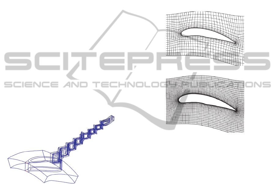
The initial geometric model of the computational
domain was based on the design documentation
provided by JSC "Kuznetsov" and it contained
domains of the middle bearing, inlet guide vanes,
and blade wheel (BW), guide vanes (GV) and output
area (Figure 1). The geometry of the blades airfoils
transmitted to NUMECA as text files in the format
.geomTurbo, which previously had been formed in
the software Profiler developed in SSAU (Shablii,
Dmitrieva, 2014). The geometry of the
computational domain took into account the changes
in the diameter of the compressor under the
influence of the heat and centrifugal loads (Matveev,
Popov, Goryachkin, Smirnova, 2014).
Figure 1: HPC computational model of NK-36ST.
The calculation model of the HPC took into
account the presence of a radial clearance over the
rotor blades, the values of which in the operation
have been taken on the recommendations JSC
"Kuznetsov". Also in the model, the presence of the
working fluid bleed after the BW of fourth turbine
cooling stage in an amount of 2.75% of the total air
flow rate at the compressor inlet was taken into
account.
The created model was divided into the finite
volumes by block-structured grid using internal tools
of the software NUMECA. Two grid models were
created. Model №1 contained two million of the
finite volumes. On average the one BR had 120
thousand of the finite volumes. The maximum value
of the parameter y + for this grid was 12. Model №2
contained 8.2 million of the finite volumes. On
average, the one BW had 500 thousand of the finite
volumes. The maximum value of the parameter y +
for this grid was 1. To improve the description
quality of the processes in the boundary layers in
both models, in the description of turbulence the
option Extended Wall Function was used.
Comparison of the finite volumes mesh of the
models №1 and №2 is shown in Figure 2. In the
considered computational domain the space around
the rotor blade and guide vanes was allocated.
а)
b)
Figure 2: Comparative picture of the finite volumes grid of
the models №1 (a) and №2 (b).
As the boundary conditions at the inlet of the
HPC the value of the total pressure was set equal to
р
*
=101,325kPa and the total temperature was equal
to T * = 288,15K. The flow direction at the inlet of
the computational domain 30
is relative to the
axis of rotation. k-ε turbulence model was used.
Parameters of the turbulence at the inlet boundary
are k=5m
2
/с
2
,
=30000 m
2
/с
3.
To evaluate the quality of the grid models
created by program Numeca Fine Turbo the
characteristics head branches of the engine NK-
36ST were calculated at rotor speeds n=90, 95, 100
и 102% (the rotational speed n=100% corresponds
to the GTP work at power in the output shaft is equal
to 25 MW). The obtained results were compared
with the experimental studies data of the considered
compressor which was provided by JSC
"Kuznetsov".
Characteristics are presented as the parameters
that correspond to the operating mode with the rotor
speed of 100 rev / min.
SIMULTECH2015-5thInternationalConferenceonSimulationandModelingMethodologies,Technologiesand
Applications
228
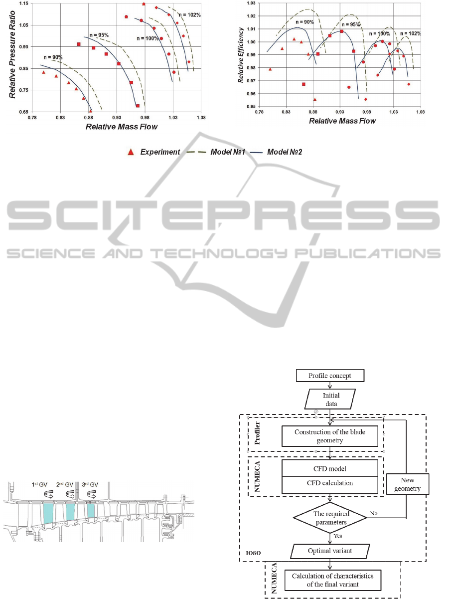
Head characteristic
Efficiency characteristic
Figure 3: Comparison of the characteristics, obtained by the different grid models, of the investigated HPC with the
experimental data.
The results of the comparison are shown in Figure 3.
It shows the dimensionless characteristics of the
NK-36ST HPC as two dependences: the relative
compression ratio and the relative efficiency of the
relative air flow rate through the compressor.
As it can be seen from Figure 3, the both created
numerical models show the good qualitative
coincidence with the experimental results. However,
the model №2 shows significantly better quantitative
coincidence with the experimental results. The
difference of values for the efficiency and the
compression ratio is not more than 2%. For this
reason, the model №2 was used for further studies.
Streamline workflow of the HPC BY THE GUIDE
VANES stagger angle of the first stages/
In the first phase, by agreement with JSC
"Kuznetsov", it was decided to find out how the
HPC efficiency can be improved at operation mode
is n = 100% by changing the stagger angles of the
guide vanes of the first three stages (Figure 4). The
range of variation of the stagger angles was limited
by company to 5 of the initial values for the
maximum preservation of the parts of the existing
engine.
Figure 4: Guide vanes, the stagger angles of which have
changed.
It was decided for finding the maximum
efficiency to use the methods of the mathematical
optimization. In particular, the program IOSO was
used. It is based on the optimization method which
based on the creating of the response surface, which
is refined and evolved for each access to calculation
model. A detailed description of the algorithm IOSO
can be found in the work (Egorov, Kretinin,
Leshchenko, Kuptzov, 2002).
The search algorithm of the optimal geometry of
the compressor on the basis the three-dimensional
numerical simulation under the control of program
optimizer IOSO (Figure 5) was developed to solve
this problem. It is as follows. The program IOSO
generates the input data block based on which the
software Profiler changes the geometry of the blades
(changes the stagger angle) and transmits it as the
text file in NUMECA.
Figure 5: Search algorithm of the optimal form of the
compressor blades using the software package IOSO.
Applicationof3DNavier-StokesEquationsandMathematicalOptimizationTechniquestoImprovetheEfficiencyof
Seven-StageAxialCompressor
229
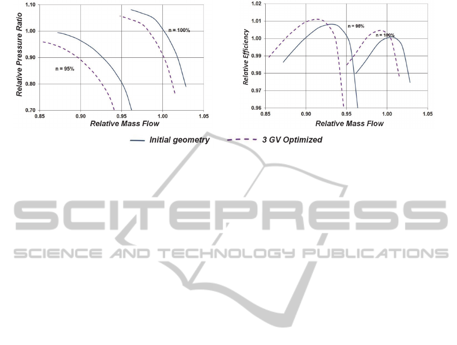
Figure 6: Comparison of the characteristics of the initial HPC with characteristics of the compressor with optimized stagger
angles of the first three stages.
There, on the basis of the obtained information,
the computational model was created and the flow
was calculated in it as a result of which the
compressor efficiency and other parameters is
determined, the results were written to the output
file. IOSO wrote this file and on the basis of
calculation, as well as calls to previous numerical
model, created the new combination of the input
data and the process is repeated to the required
extremum.
The software package IOSO had 102 calls to
computational model to solve the problem of
optimization. The total computation time was more
than 150 hours of computer time on cluster of 10
PCs.
Figure 6 shows comparison of the characteristics
of the initial and optimized version of the HPC. An
analysis of the obtained results shows that by
decreasing the stagger angles of the GV in 1, 2 and 3
stages at 1.9480, 1.9470 and 1.7290 degrees
respectively it succeeded to increase the efficiency
of the compressor at the HPC rotor speed n = 100%
to 0,3% (abs.). The efficiency increase caused by
matching of the contact angles of the first stages.
The decrease in the GV stagger angles has led to the
fact that the сщккусеув specific air flow rate in the
considered mode is decreased by 1.3%, that may
cause the decrease in the engine power.
Thus, it was demonstrated that by correcting of
the stagger angles of the GV it's possible to achieve
the increase of the HPC efficiency, but this increase
is not a significantly. In addition by the results of the
study it had concluded to save the joint work of
nodes while optimizing it should the impose
restrictions on the position of key operating point on
the characteristic of the compressor. Streamline
workflow HPC by stagger angles of all blade rows.
According to the studies results which described
above the JSC "Kuznetsov" was convinced that the
significant increase of the efficiency of HPC is not
possible by changing the number of the blade rows .
For this reason, the task has been adjusted. It was
instructed to determine how the efficiency of the
considered HPC can be increased by changing of the
blade rows stagger angles, which are placed there.
Together with this it was tasked to achieve the
efficiency increase of the HPC not only at rotational
speed of 100%, but at rotational speed of 95%, while
maintaining the flow rate and the compression ratio
at these operation modes.
To reach the given task the problem of
optimization has been changed. Maximum
efficiencies of the compressor at the relative
rotational speeds of 95% and 100% were selected as
optimization criteria.
In order to prevent the shift of characteristics of
the compressor, in agreement with the JSC
"Kuznetsov", the following restrictions were set in
the optimization:
the flow rate of the working fluid through the
HPC at the relative frequency of rotation of
95% was not supposed to be different from the
respective flow rate of the base compressor
more than ±1,3%;
the flow rate of the working fluid through the
HPC at relative frequency of rotation of 100%
was not supposed to be different from the
respective flow rate of the base compressor
more than ±0,6%;
the value change of the HPC pressure ratio in
comparison with the base compressor at points
of the maximum efficiency at relative
rotational speeds of 95% and 100% was
allowed within ±1,5%.
The stagger angles of all rotor blades, the GV and
IGV of the HPC were selected as varied variables.
SIMULTECH2015-5thInternationalConferenceonSimulationandModelingMethodologies,Technologiesand
Applications
230
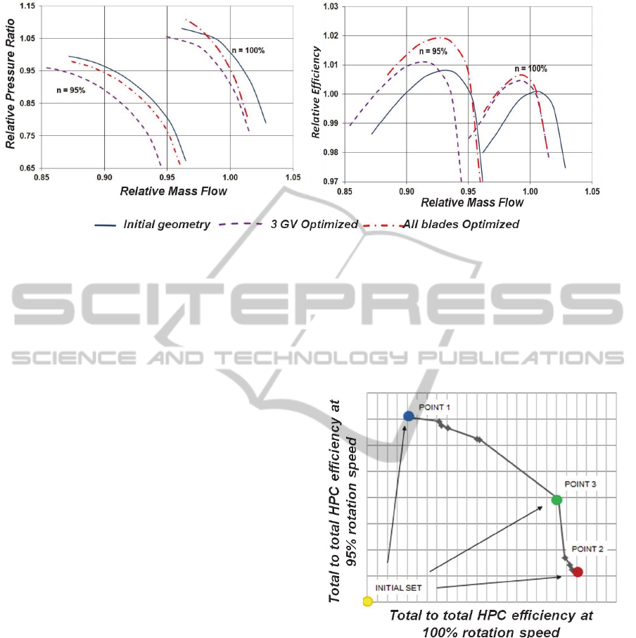
Figure 7: Comparison of the characteristics of optimized versions of the compressor and basic HPC.
The range of the stagger angles change of the vanes
of each blade row has been selected so that during
the blades rotation their profiles fits into the existing
blade stoppers. The blades number in the row wasn't
changed. This solution allowed to find the variant to
increase the efficiency of the HPC, that would not
require the modification of the disk and the body
parts of the compressor. The total number of the
changed variables was 15.
To solve the formulated problem of the
optimization the software package IOSO had 446
calls to the numerical model of the HPC. Each call
to the numerical model is calculation of two points
on the characteristic of the HPC (points of the
maximum efficiency on the branches corresponding
to the relative frequency of the rotation of 95% and
100%) in the software package NUMECA
FineTurbo.
As a result, a lot of unimprovable solutions
(Pareto set) were obtained, which are a compromise
between the increase of efficiency at the relative
rotational speed of 95% and the increase of
efficiency at the relative rotational speed of 100%
(Figure 8). Each point of Pareto set corresponds to
the unique geometry of the HPC which is
represented as an array of the stagger angles of all
blade rows of the HPC.
Analysis of the extreme points of Pareto set
shown that at relative rotation frequency of 95% the
highest increase of the maximum efficiency is 1.8%
(abs.) at the substantially constant maximum
efficiency at the relative rotational speed of 100%
(point 1 of Pareto set in Figure 8). When the relative
rotational speed is 100% the highest increase of
maximum efficiency is 0.6% (abs.) at the increase of
the maximum efficiency at relative rotational speed
of 80% to 1% (point 2 Pareto set in Figure 8).
However, for further research the one of midpoints
of the set Pareto have been selected (point 3 in
Figure 8), which is provide the increase of the
efficiency as at relative rotation frequency of 100%
(0.5% (abs.)) and at the relative frequency rotation
of 95 % (1.2% (abs.)).
Figure 8: Pareto set.
The numerical model of the HPC corresponding to
the selected point #3 of the Pareto set was created to
analyze the results of the optimization. The
characteristics of optimized version of the HPC at
the relative rotational speeds of 95% and 100% were
obtained by this numerical model and their
comparison with the characteristics of the HPC base
version (Figure 7) and with the searching results of
the optimal combination of the stagger angles at the
first three stages was performed.
As the result of the comparison the following
characteristics was revealed:
Applicationof3DNavier-StokesEquationsandMathematicalOptimizationTechniquestoImprovetheEfficiencyof
Seven-StageAxialCompressor
231
the operation stall margin of the optimized
HPC was changed slightly in comparison
with the base case at the investigated rotation
frequencies;
the values change of the air flow rate and the
compressor pressure ratio of the optimized
HPC at points of the maximum efficiency at
the investigated rotation frequencies is within
the accepted limits;
the HPC efficiency at the relative rotation
frequency of 95% has increased by 1.2%
(abs.) and at relative rotation frequency of
100% the increase of efficiency was 0.5%
(abs.).
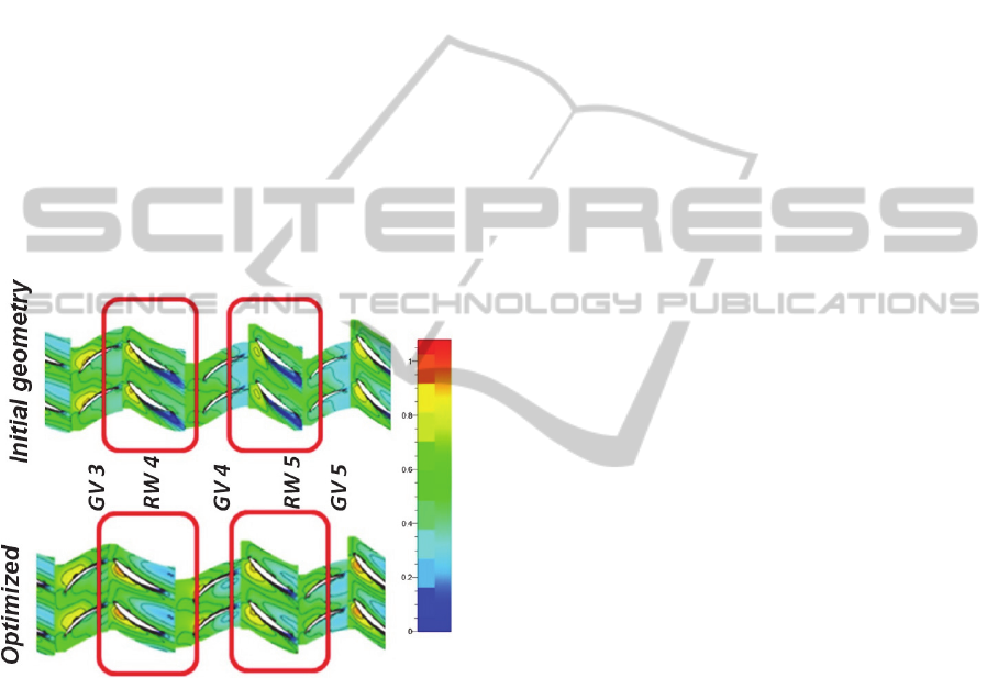
Analysis of the flow structure in the optimized
version of the HPC at the point of the maximum
efficiency at the relative rotation frequency of 100%
shown that the optimization of the HPC blades
stagger angles has removed the stall in the hub
section of the fourth and fifth HPC BW (Figure 9).
Figure 9: Comparison of the fields of the relative Mach
number near the hub section of the base and optimized
HPC.
3 CONCLUSIONS
As a result of the work described above the
searching algorithm the optimal form of compressor
blades by numerical models of workflow in program
NUMECA and optimizer
program IOSO has been
developed and implemented.
The adequacy of the developed method has been
proved by the example of solving the problem of
optimization of the high pressure compressor of real
gas turbine plant.
It was found the configuration of the compressor
allowing to obtain improved efficiency by 1.2% at
the rotating frequency of 95% and efficiency by
0.5% at the rotation frequency of the rotor of 100%.
Changing the shape of blades,the guide vanes
and the flow part during optimization has allowed to
obtain the higher values of efficiency of the
compressor.
ACKNOWLEDGEMENTS
This work was supported by the Ministry of
Education and Science of the Russian Federation in
execution of the order №218 from 09.04.2010
(theme code 2013-218-04-4777).
The work was financially supported by the
Ministry of education and science of Russia in the
framework of basic part of government assignment.
REFERENCES
Kulagin, V., 2002. The theory, calculation and design of
aircraft engines and power plants Fundamentals of the
theory of the CCD. Workflow and thermodynamic
analysis, Mashinostroenie, Moskow.
Kuzmichev, V., Rybakov, V., Tkacheno, A., Krupenich,
I., 2014. Optimization of working process parameters
of gas turbine engines line on the basis of unified
engine core. In ARPN Journal of Engineering and
Applied Sciences, vol. 9, pp 1873-1878.
Shablii, L., Dmitrieva, I., 2014. Blade geometry
transformation in optimization problems from the
point cloud to the parametric form. In Russian
Aeronautics, vol. no 3, pp. 276–282.
Matveev, V., Popov, G., Goryachkin, E., Smirnova, Y.,
2014. Effect of Accounting of Air Bleed from the
Flow Passage of the Multi-Stage Axial Low Pressure
Compressor on its Design Performances. In Research
Journal of Applied Sciences, vol. 9, no. 11, pp. 784-
788.
Egorov, I., Kretinin, G, Leshchenko, I., Kuptzov, S., 2002.
Optimisation Toolkit - Novel Software to Create
Better Design. In Proc. of 9th AIAA/ISSMO
Symposium on Multidisciplinary Analysis and
Optimisation.
SIMULTECH2015-5thInternationalConferenceonSimulationandModelingMethodologies,Technologiesand
Applications
232
