
IT-enabled Management of Sharing Logistic Trucks
Ichiro Satoh
National Institute of Informatics, 2-1-2 Hitotsubashi, Chiyoda-ku, Tokyo 101-8430, Japan
Keywords:
Carbon Emission, Earth-friendly Logistics, Process Calculus.
Abstract:
This paper proposes a management system for sharing trucks as cooperative logistics. To reduce fossil fuel
consumption and carbon dioxide emissions resulting from transport, we should improve transport efficiency
of trucks, which play an essential role as carriers in modern logistics services. We propose a language for
specifying the routes of trucks and an order relation between the requirements of routes and the possible
routes of trucks. The former is formulated as process calculus and the latter selects suitable trucks whose
itineraries can satisfy the requirements of users and are more friendly the environment.
1 INTRODUCTION
Green logistics is important to minimize the ecolog-
ical impact of logistics activities. Transportation ac-
counts for about 23-percent of energy-related carbon
dioxide (CO
2
) emissions(Agency, 2009). IEA has ex-
pected, given current trends, energy demand and CO
2
emissions in transport nearly 80-percent higher by
2050 without any efficiency improvements. Trucks,
which play an essential role as carriers in modern lo-
gistics services, emit a huge quantity of carbon diox-
ide (CO
2
) into the atmosphere. There have been sev-
eral approaches to reducing fossil-fuel consumption
and CO
2
emissions from tracks.
• Low-emission tracks: the amount of CO
2
emis-
sion from tracks is reduce by using environmen-
tally friendly trucks, which produces less harm-
ful impacts to the environment than comparable
conventional internal combustion engine vehicles
running on gasoline or diesel, or one that uses cer-
tain alternative and sustainable fuels.
• Low-emission operation for individual tracks:
since the amount of CO
2
emission from each track
is basically in proportion to the distance traveled
by the track. Shortening such a distance can re-
duce CO
2
emission. Environmentally friendly
driving is important because driving of trucks,
e.g., slowing down and up, depends on the amount
of CO
2
emission.
• Low-emission management for trucks: the num-
ber of tracks seriously affect the amount of CO
2
emission. It is reduced by efficiently managing
trucks in addition to reducing freights.
This paper addresses cooperative logistics as a solu-
tion to the third approach. Cooperative logistics has
been expected as one of the most efficient and pop-
ular ways of improving truck-load ratios and reduc-
ing trucks. However, it tends to be complicated in
comparison with existing (non-earth-friendly) logis-
tics. In fact, several industries, e.g., food and automo-
bile manufacturers, in addition to the dairy industry,
have attempted to use cooperative logistics.
Nevertheless, most attempts to support coopera-
tive logistics have been failed because of their man-
agement problems for several reasons. There are
often conflicts between the requirements of suppli-
ers/customers and the operations of shared trucks.
Even if there are many shared trucks, it is difficult
to find trucks that can satisfy the requirements of sup-
pliers/customers, because the requirements are more
complicated than those of moving people. Most coop-
erative logistics management tends to depend on hu-
mans, e.g., logistics managers in suppliers and truck
drivers. This may be rational in a small scale cooper-
ative logistics consisting of two or three suppliers, but
seriously affect scalability. We need a systematic and
scalable approach for managing cooperative logistics.
To solve these problems, we propose an e-logistics
for sharing trucks between operators or customers
to support cooperative logistics. This paper de-
fines our e-logistics management system for sharing
trucks. The system is constructed based on a theoreti-
cal framework consisting of a process-calculus-based
language that describes truck routes and a mechanism
for selecting suitable trucks according to the require-
ments of customers. This is because the selection
17
Satoh I..
IT-enabled Management of Sharing Logistic Trucks.
DOI: 10.5220/0005571300170024
In Proceedings of the 12th International Conference on e-Business (ICE-B-2015), pages 17-24
ISBN: 978-989-758-113-7
Copyright
c
2015 SCITEPRESS (Science and Technology Publications, Lda.)
of trucks need to be exact in the sense that selected
trucks must satisfy the requirements. The mechanism
is defined based on an algebraic relation that deter-
mine whether a truck can visit various points, e.g.,
farmers and manufacturers, along its route to collect
or deliver items. It enables collection/delivery points
to select trucks according to the truck route because
the route a truck takes is critical in determining its ef-
ficiency.
2 EXAMPLE SCENARIO
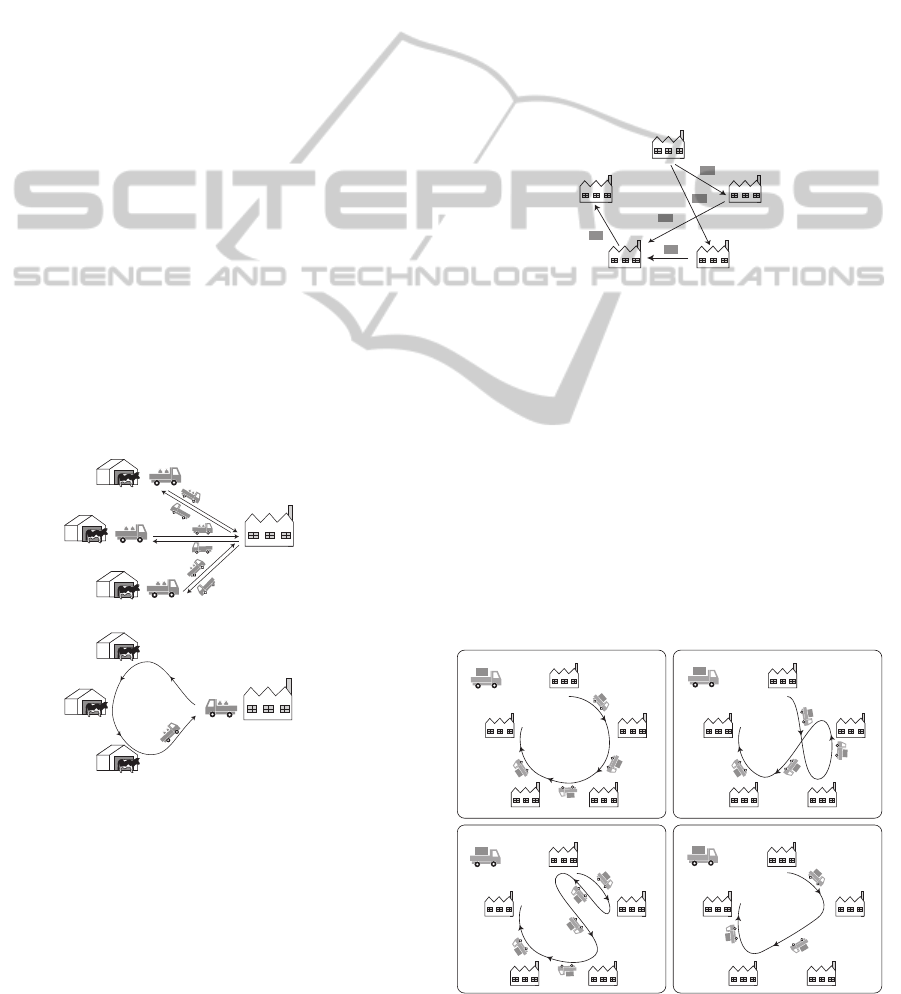
Milk-run operation is one of most typical cooperative
logistics ones for improving truck-load ratios, refers
to a means of transportation in which a single truck
cycles around multiple suppliers to collect or deliver
freight. The name is derived from the milk-runs car-
ried out by farmers collecting milk from dairy cows
spread out over pastures (Fig. 1). Using the milk-run
approach, one truck calls at each of the suppliers on a
daily basis before delivering the collected milk to the
customer’s plant. On the other hand, in a traditional
approach, e.g., the Just-In-Time approach, all suppli-
ers have their own trucks and send one truckload per
day to the customer (Fig. 1). The milk-run approach
is effective in reducing the amount of CO
2
emitted by
trucks.
Conventional approach
(three trucks)
Milk-run approach
(one truck)
Dairy factory
Dairy farmar
Dairy farmar
Dairy
farmar's
truck
Dairy
factory's
truck
Dairy
farmar's
truck
Dairy
farmar's
truck
Figure 1: Legacy approach and milk-run approach.
As mentioned previously, existing cooperative lo-
gistics has serious problems in their management.
The cooperative logistics approach needs for logis-
tics operators to provide multiple trucks using varied
routes to satisfy the needs of customers and cater for
the requirements of the products. Therefore, the cus-
tomers are confronted by another problem: they need
to design truck routes and select suitable trucks with
routes that satisfy their requirements. For example,
suppose five suppliers, e.g., dairy farmers, send their
products to the processing plant every weekday. Fig-
ure 2 shows five factories, A, B, C, D, and E, that have
the following dependencies:
• Factory A manufactures products and ships the
products to factories B and C.
• Factory B manufactures products and ships the
products to factory D.
• Factory C manufactures products and ships the
products to factory D.
• Factory D manufactures products and ships the
products to factory E.
E
D
C
Factory A
B
Product
Figure 2: Five factories with dependencies.
We assume that a truck has sufficient carrying ca-
pacity. It starts at factory A and may visit factory
A again. Figure 3 shows four trucks carrying out
milk-runs on different routes. The first, second, and
third trucks can satisfy the above requirements but the
fourth cannot. The third is less efficient than the first
and second on their rounds. The system proposed in
this paper was inspired by our real experiences. Al-
though the milk-run approach is effective in reducing
the amount of CO
2
emitted by trucks, its management
tends to be complicated, which is one of the most sig-
nificant barriers preventing wider adoption of the ap-
proach in real logistics.
Truck 1
A
E
D
C
B
Truck 2
A
E
D
C
B
Truck 3
A
E
D
C
B
Truck 4
A
E
D
C
B
Figure 3: Four trucks for milk-run operation.
ICE-B2015-InternationalConferenceone-Business
18

This paper assumes that one or more trucks in-
volved in milk-run logistics operations call at multi-
ple points along their routes. Customers and suppliers
have to decide which truck and which route will best
satisfy their requirements, and this decision is not an
easy one.
3 REQUIREMENTS
The proposed e-logistics system was inspired from
our discussions on real logistics companies. The
system must therefore satisfy the following require-
ments:
• In cooperative logistics trucks may be shared by
multiple customers, so that they collect products
at one or more source points and deliver the prod-
ucts at one or more destination points on their
way. The trucks need to visit the source points
before they visit the destination points. Our sys-
tem therefore needs to specify the order in which
trucks call at various points.
• Some products may be collected/delivered at
points by trucks without any need for a specific
order of arrival at collection/delivery points. That
is, the order of the movement of trucks between
points does not affect the efficiency of the trucks’
operations. Suppliers or customers should select a
truck according to the number of movements be-
tween the points that the trucks visit.
• One or more trucks are available in cooperative
logistics, but their routes may be different. Most
logistic trucks runs their driving plans, which
were submitted to or assigned by truck opera-
tors’ offices, although they may be changed daily,
weekly, or monthly. That is, trucks do not change
their routes after starting their operations.
• Our e-logistics management system should re-
ceives the routes submitted by truck operators and
maintains the routes in its database. When it re-
ceives queries about the trucks that can satisfy the
requirements of customers, it returns such trucks
to them. The system should provide truck opera-
tors and customers with web-based interfaces.
• Pallets or boxes that contain multiple products are
considered as transport units in many current lo-
gistics systems, rather than as individual products.
These types of containers may have multiple des-
tinations required by their inner products and the
receivers may take only some of the products in
the container when it arrives at their point.
4 APPROACH
The selection of the routes of trucks for cooperative
logistics, including milk-run operations, is critical for
industrial efficiency and for minimizing carbon diox-
ide emissions. Careful consideration must be given
to selecting suitable trucks with routes that satisfy the
requirements of customers and suppliers. To select
suitable trucks exactly, our e-logistics management
system should be constructed based on a theoretical
framework.
• It provides a specification language for describ-
ing and analyzing truck routes. The language
is aimed at specifying only the routes of trucks
formulated as an extended process calculus with
the expressiveness of truck routes between collec-
tion/delivery points.
• It defines an algebraic order relation over the
terms of the language. The relation is defined
based on the notion of bisimulation and compares
possible truck routes and the routes required by its
specifications. This allows us to accurately deter-
mine whether the former satisfies the latter.
Note that the order relation is not intended to gener-
ate the most efficient route, because truck routes tend
to be designed according to external factors. Thus,
the computational complexity for this relation is not
large. Some readers may think that simple executable
languages, such as Lisp and Prolog, should be used
to specify routes, but it is difficult to verify whether
or not routes written in such languages will satisfy
the requirements of customers and suppliers because
these languages have many primitives that are not
used in describing routes. We explain the reason why
our e-logistics management system is constructed as
a process calculus-based approach, because itinerary
plans, which transporters are obligated to make for
their trucks, can be treated as the sequences of desti-
nations that the truck visit like expressions of process
calculi. Therefore, we can easily transform itinerary
plans for trucks into process calculus-based specifica-
tion in comparison with other approaches, i.e., logic-
based and graph-based specifications.
5 TRUCK SHARING MODEL
This section defines our model for sharing logistic
trucks. The model provides a language for speci-
fying about truck routes and a system for selecting
the routes that can satisfy the requirements of suppli-
ers/customers. The language consists of two classes.
The first is designed to specify truck routes and the
IT-enabledManagementofSharingLogisticTrucks
19

second is designed to specify the routes required by
products or customers.
Definition 1. The set E of expressions of the lan-
guage, ranged over by E,E
1
,E
2
,... is defined recur-
sively by the following abstract syntax:
E ::=
0
| ℓ | E
1
;
E
2
| E
1
+
E
2
| E
1
#
E
2
| E
1
%
E
2
| E
1
&
E
2
| E
*
where L is the set of location names ranged over by
ℓ, ℓ
1
,ℓ
2
,..., and where points correspond to the loca-
tions of suppliers and customers. We often omit
0
.
We describe a subset language of E as S , when elim-
inating E
1
#
E
2
, E
1
%
E
2
, E
1
&
E
2
, and E
*
from E . Let
S, S
1
,S
2
,... be elements of S.
⊓
⊔
Our e-logistics system assumes that each truck has its
own route written in S and that its driver visits points
along the route. Although its semantics is defined in
the Appendix, we describe intuitive meaning of the
terms is as follows:
•
0
represents a terminated route.
• ℓ represents that a truck moves to a point called ℓ.
• E
1
;
E
2
denotes the sequential composition of two
routes E
1
and E
2
. If the route of E
1
terminates,
then the route of E
2
follows that of E
1
.
• E
1
+
E
2
represents the route of a truck according to
either E
1
or E
2
, where the selection is done by the
truck.
• E
1
#
E
2
means that a truck itself can go through ei-
ther E
1
or E
2
.
• E
1
%
E
2
means that a truck can follow either E
1
be-
fore E
2
or E
2
before E
1
on its route.
• E
1
&
E
2
means that two routes, E
1
and E
2
, may be
executed asynchronously.
• E
*
is a transitive closure of E and means that a
truck may move along E an arbitrary number of
times.
where in E
1
+
E
2
the truck can select the E
1
(or E
2
)
route when the E
1
route is available. For example, if
the E
1
route is available and the E
2
route is congested,
the truck goes through the E
1
route. E
1
#
E
2
means
that a truck can go through either E
1
or E
2
. E
1
%
E
2
,
E
1
&
E
2
, and E
*
are used to specify possible routes.
1
For example, E
1
#
E
2
permits the truck to go through
one of the E
1
or E
2
routes.
We show several basic examples of the language
as shown in Fig. 4. The first diagram in Fig. 4
1
E
*
specifies that the truck follows the E route more than
zero times like the notion of Kleene closure. The operator
is used to specify that the requirement of a truck’s route
permits the truck to visit specified destinations if the truck
wants to do this.
a
e
d
c
b
a
e
d
c
b
a;(b#c);d;e
a;(b%c);d;e
a;((b;c)&d);e
a
e
d
c
b
a
e
d
c
b
a;b;c;d;e
Figure 4: Examples of specification.
shows the transitions of a
;
b
;
c
;
d, the second shows
a
;
(b
#
c)
;
d
;
e the third shows a
;
(b
%
c)
;
d
;
e, and
the fourth shows a
;
((b
;
c)
&
d)
;
e.
We formally defines a system for selecting the
routes of trucks that can satisfy the requirements in
the Appendix. The system selects trucks according
to their routes based on the concept of bisimulation
(Milner, 1989). The relation is suitable for selecting
a truck for a milk-run operation with a route that sat-
isfies the requirements of suppliers and customers, as
specified an inequality E ⊒
n
S. The informal meaning
of E ⊒
n
S is that S is included in one of the permissible
routes specified in E and n corresponds to the number
of movements of a truck that can satisfy E. Since
the language supports an external selection operator,
i.e., +, like other process calculi, our truck selection
cannot be defined as simple algebraic relations, e.g.,
trace-based semantics. We show several basic proper-
ties of the order relation below. Let us look at some
basic examples.
• (a
%
b)
;
c ⊒
3
a
;
b
;
c
where the left-hand-side requires a truck to carry
products to a, and b in an indefinite order and then
return to point c; the right-hand-side requires a
truck to carry products to three points, a, b, and c,
sequentially. When the right-hand-sideis changed
to b
;
a
;
c, the relation is still preserved, but when
the right-hand-side becomes c
;
a
;
b or a
;
c
;
b,
the relation is not preserved.
• (a
;
b
;
c)
#
(a
;
c
;
b
;
c) ⊒
3
a
;
b
;
c
where the left-hand-side means that a truck fol-
lows one of either a
;
b
;
c or b
;
c
;
a. When the
right-hand-side becomes a
;
c
;
b
;
c, the relation
ICE-B2015-InternationalConferenceone-Business
20
is not preserved, because ⊒
3
means that the truck
can visit its destinations at most three times. Nev-
ertheless, ⊒
4
is preserved with a
;
c
;
b
;
c at its
right-hand-side.
• ((a
;
b
;
c)
&
d
*
)
;
d ⊒
6
a
;
d
;
b
;
d
;
c
;
d
where the left-hand-side allows a truck to drop
in at point d an arbitrary number of times on
route a
;
b
;
c and then finish its movementat point
d. The right-hand-side is a star-shaped route
between three destinations, a, b, c, and point
d satisfies the left-hand-side. When the right-
hand-side becomes a
;
b
;
d
;
c
;
d, a
;
d
;
b
;
c
;
d,
or a
;
b
;
c
;
d, the relation is preserved, but
a
;
b
;
c
;
d is the most efficient route.
6 E-LOGISTICS MANAGEMENT
SYSTEM FOR SHARING
TRUCKS
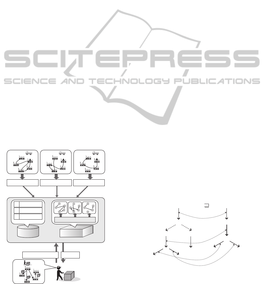
This section describes a prototype implementation
of our e-logistics system. The experiment was con-
structed as a distributed logistics management system
consisting of six supplier points in addition to a cus-
tomer point with a route-selection server. Figure 5
shows the basic structure of the system. The server
was responsible for receivingroute requirements from
suppliers and customers through a network and se-
lecting suitable trucks with routes that satisfied these
requirements.
a
b
c
d
e
Truck 1
a
b
c
d
e
Truck 2
a
b
c
d
e
Truck 3
a;b;e;c;d;e
a;c;b;d;e a;b;d;e
Database
Verification
engine
a;b;e;c;d;e
1
2
3
a;c;b;d;e
a;b;d;e
1
2
3
Bisimulation
e-Logistics system for managing shared trucks
Step 2:
Submitting routes
Step 1:Specifying routes
a
b
c
d
e
(a;(b%c))&(a;d;e) Truck 2
Step 3: Querying about the trucks
that can satisfy the requirement.
Step 4: Selecting trucks
Customer
When more than one truck
can satisfy the requirement,
the truck that has the shortest
route is selected
Requirement
Figure 5: Basic structure of logistics management system.
6.1 Route Selection Algorithm
Here, let us explain the selection algorithm used for
the current implementation, which we tried to make
as faithful to Definition 3 as possible. The server
maintains its own repository database containing the
routes of trucks. To reduce the cost of the selection
algorithm, the possible routes written in E are trans-
formed into tree structures before they are stored in
the database. These are called
transition trees
or
derivation trees
in the literature on process cal-
culus (Milner, 1989). Each tree is derived from a
route in E according to Definition 2 and consists of
arcs corresponding to ℓ-transitions or τ-transitions in
the route. When a route selection server receives a
required route from suppliers or customers, it extracts
the required route written in S and then transforms the
route into a transition tree. It next determines whether
or not the trees derived from the routes stored in the
database system can satisfy the tree derived from the
required route by matching the two trees according to
the definition of the order relation (⊒
n
⊆ E × S) as in
the following.
(1) If each node in one of the two trees has arcs corre-
sponding to ℓ-transitions, then the corresponding
node in the other tree can have the same arcs, and
the sub-nodes derived through the matching arcs
of the two trees can still satisfy either (1) or (2).
(2) If each node in the tree derived from the required
route has one or more arcs corresponding to τ-
transitions, then at least one of the nodes derived
through the arcs and the corresponding node in the
tree derived from the truck’s route can still satisfy
(1) or (2).
(3) If neither (1) nor (2) is satisfied, the route selec-
tion server backtracks from the current nodes in
the two trees and tries to apply (1) or (2) to their
two backtracked nodes.
a;b;(c+d)a;((b;(c+d))#d)
(b;(c+d))#d
τ
τ
b;(c+d)
d
b;(c+d)
c+d
dc
dc
a
a
b
b
d
3
Figure 6: Matching transition trees in route-order relation
algorithm.
Figure 6 illustrates the matching of two transition
trees in the above algorithm. If one or more truck
IT-enabledManagementofSharingLogisticTrucks
21

routes in the database satisfy the required route, it se-
lects the truck with the least number of truck move-
ment between points, which is n of ⊒
n
in Definition
3. Although the cost of selecting a route is dependent
on the number of trucks and the length of their routes,
the system can handle each of the routes presented in
this paper within a few milliseconds.
Non-deterministic operators, e.g.,
#
and
%
, tend
to cause the exposition of a number of sub-trees in
transition trees. Nevertheless, our algorithm can eas-
ily restrain the number of sub-trees resulting from
non-deterministic operators because the expansion
rules of expressions, i.e., the operational semantics
of the language, distinguish between derivations re-
sulting from deterministic operators and those result-
ing from non-deterministic operators. Readers may
wonder why E
*
operator creates an infinite number
of sub-trees, but the current implementation interprets
the operator in a lazy evaluation manner.
Route
Database
Client (Supplier A)
Client (Supplier C)
Client (Supplier B)
Recommended
truck identifier
Route
RFID tag reader
RFID tag reader
RFID tag
reader
Box with
RFID tag
Box with
RFID tag
Box with RFID tag
Recommended truck
Recommended truck
Required route
in RFID tag
Required route
in RFID tag
Required route
in RFID tag
Route
Selection
Engine
Route selection server
Route
Route
Figure 7: Experiment.
We have implemented the e-logistics system on a
PaaS cloud computing infrastructure, called Google’
App Engine. Trucks’ routes are maintained in a key-
value store, called Bigtable, provided by the infras-
tructure. When our system receives a truck route
from a truck operator, it transforms the required route
into a tree structure and stores the structure into the
Bigtable database. When it receives a request with a
required route, our route selector engine transforms
the required route into a tree structure and matches
between the structure and the structures correspond-
ing to trucks’ routes. This means truck operators and
suppliers do not need any special equipment to use
the logistics management system. This is important
because in cooperative logistics, most suppliers are
small to medium enterprises that do not want to have
to invest in additional equipment for cooperative lo-
gistics.
The current implementation assumes that the
routes required for products or pallets are stored in
RFID tags attached to the products or pallets because
they may have their own delivery requirements. It
assumes that each client-side system at a supplier or
customer point has more than one RFID tag reader,
which periodically or explicitly tries to detect the
presence of tags within its coverage area. It supported
Phillips i-Code system (13.56 MHz), which provides
each tag with 112 bytes. We were able to maintain
each of the example routes presented in these papers
in the first and second tag systems, where the length of
the identifier for each point was 4 bytes. The current
implementation of the algorithm was not optimized
for performance. Nevertheless, we describe the ba-
sic performance of the implementation. By using an
RFID reader embedded with a WiFi network inter-
face, the cost of reading the route specification in a
tag depends on the length of the specification, e.g. the
cost of reading a specification with a length of less
than 40 bytes is within 0.2 sec. When the routes of
five trucks were registered in the server running on a
computer (Intel Core 2 Duo 2 GHz and WindowsXP),
the cost of selecting a truck after the reader had de-
tected a tag, including the cost of communication be-
tween the server and client via a TCP/IP session, was
less than 1.2 sec. Client-side systems for suppliers
and customers can be operated using only RFID read-
ers, which connect to a server through either wired
or wireless networks. This means they do not need
any special equipment to use the logistics manage-
ment system. This is important because in milk-run
logistics, most suppliers are small to medium enter-
prises that do not want to have to invest in additional
equipment for milk-run logistics.
7 RELATED WORK
There have been many attempts to use process calculi,
e.g., as formal methods for various businessenterprise
processes. Several researchers have used process cal-
culi, e.g., π-calculus, as business-process modeling
languages, such as BPEL, (K. Xu, 2006; M. Mazzara,
2006; F. Puhlmann, 2005; Smith, 2003). π-calculus
has been used as a formal composition language for
software composition and Web service composition,
e.g., Orc (J. Misra, 2004) and SCC (M. Boreale and
Zavattaro, 2006). Process calculi are theoretically
sound and support bisimulation analysis and model
checking. They are also gaining increasing accep-
tance as a support tool in industry. However, there
have been no process-calculus-based formal methods
for logistics, in particular for improving the transport
efficiency of trucks.
ICE-B2015-InternationalConferenceone-Business
22

8 CONCLUSIONS
This paper presented an e-logistics system for man-
aging for shared trucks to reduce the environmental
impacts of transport operations. The system was for-
mulated based on a process calculus-based language
and an order relation over two terms corresponding
to truck routes and the required routes in the lan-
guage. The language could specify truck routes for
milk-run operations and the required routes for ship-
ping. The relation could be used to accurately deter-
mine whether a truck route satisfies the requirements
of customers and suppliers. A prototype implementa-
tion system based on the framework was constructed
using Java language and RFID tag systems and ap-
plied to our experimental distributed logistics man-
agement system.
REFERENCES
Agency, I. E. (2009). Transport energy and co2 (moving
toward sustainability). Technical report, International
Energy Agency.
L. Cardelli and A. D. Gordon. Mobile Ambients, Proceed-
ings of Foundations of Software Science and Compu-
tational Structures. in Springer, 1998.
F. Puhlmann, M. W. (2005). Using the pi-calculus for for-
malizing workflow patterns. In Proceedings of In-
ternational Conference on Business Process Manage-
ment.
J. Misra, W. R. C. Computation orchestration: A basis for
wide-area computing. In Journal of Software and Sys-
tems Modeling.
K. Xu, Y. Liu, J. Z. C. W. (2006). Pi-calculus based bi-
transformation of state-driven model and flow-driven
model. International Journal of Business Process In-
tegration and Management, 1(4).
M. Boreale, R. Bruni, L. Caires, R. De Nicola, I. Lanese,
M. Loreti, F. Martins, U. Montanari, A. Ravara, D.
Sangiorgi, V. T. Vasconcelos, and G. Zavattaro Scc:
a service centered calculus. ”Proceedings of Web Ser-
vices and Formal Methods”, in Springer 2006.
M. Mazzara, R. L. (2006). A pi-calculus based semantics
for ws-bpel. Journal of Logic and Algebraic Program-
ming, 70(1).
Milner, R. (1989). Communication and Concurrency. Pren-
tice Hall.
Smith, H. (2003). Business process management-the third
wave: Business process modeling language (bpml)
and its pi-calculus foundations. Information and Soft-
ware Technology, 45(15).
APPENDIX
To accurately express such routes, we need to define
a specification language based on a process calculus
approach such as CCS (Milner, 1989). The semantics
of the language are defined by the following labeled
transition rules:
Definition 2. The language is a labeled transition
system h E, L ∪ {τ} {
α
−→⊆ E × E |α ∈ E ∪ {τ} } i.
The transition relation −→ is defined by two kinds of
axioms or induction rules as given below:
−
ℓ
ℓ
−→
0
E
1
ℓ
−→ E
′
1
E
1
;
E
2
ℓ
−→ E
′
1
;
E
2
E
1
ℓ
−→ E
′
1
E
1
+
E
2
ℓ
−→ E
′
1
E
2
ℓ
−→ E
′
2
E
1
+
E
2
ℓ
−→ E
′
2
E
1
ℓ
−→ E
′
1
E
1
&
E
2
ℓ
−→ E
′
1
&
E
2
E
2
ℓ
−→ E
′
2
E
1
&
E
2
ℓ
−→ E
1
&
E
′
2
−
E
1
#
E
2
τ
−→ E
1
−
E
1
#
E
2
τ
−→ E
2
−
E
1
%
E
2
τ
−→ E
1
;
E
2
−
E
1
%
E
2
τ
−→ E
2
;
E
1
E
1
τ
−→ E
′
1
E
1
;
E
2
τ
−→ E
′
1
;
E
2
E
1
τ
−→ E
′
1
E
1
+
E
2
τ
−→ E
′
1
E
2
τ
−→ E
′
2
E
1
+
E
2
τ
−→ E
′
2
E
1
τ
−→ E
′
1
E
1
&
E
2
τ
−→ E
′
1
&
E
2
E
2
τ
−→ E
′
2
E
1
&
E
2
τ
−→ E
1
&
E
′
2
where
0;
E, E
&0
, and
0&
E are treated to be syn-
tactically equal to E and E
*
is recursively defined
as
0#
(E
;
E
*
). We often abbreviate E
0
τ
−→ E
1
τ
−→
···
τ
−→ E
n−1
τ
−→ E
n
to E
0
(
τ
−→)
n
E
n
.
⊓
⊔
In Definition 2, the ℓ-transition defines the semantics
of a trucks movement. For example E
ℓ
−→ E
′
means
that the truck moves to a point named ℓ and then be-
haves as E
′
. Also, if there are two possible transi-
tions E
ℓ
1
−→ E
1
and E
ℓ
2
−→ E
2
for a truck, the process-
ing by the truck chooses one of the destinations, ℓ
1
or ℓ
2
. In contrast, the τ-transition corresponds to a
non-deterministic choice of a truck’s routes .
Readers may think that the above operational se-
mantics could be more compact. However, the aim
is to design a system that can be easily implemented
because the purpose of our e-logistics system is not
to provide just a theoretical foundation for determin-
ing truck-route logistics, but a practical mechanism
for selecting suitable trucks for milk-run operations.
The language does not needs recursive or loop nota-
IT-enabledManagementofSharingLogisticTrucks
23

tions, because each truck does not continue to run for
24 hours everyday.
• Route specification, a
;
b
;
c
;
d, in S is interpreted
as follows:
a
;
b
;
c
;
d
a
−→ b
;
c
;
d
b
−→ c
;
d
c
−→ d
d
−→
The first diagram in Fig. 4 illustrates the above
derivation.
• Next, we show an example of a specification in E.
This is a route requirement.
a
;
(b
#
c)
;
d
;
e
a
−→ (b
#
c)
;
d
;
e
τ
−→ b
;
d
;
e or c
;
d
;
e
where
#
corresponds to a combination of two re-
quired routes so that trucks are required to follow
both routes as shown in the third diagram in Fig.
4. That is, a truck needs to call at point a and then
at either b or c. Next, it calls at d and then e.
• We show another route requirement specification,
a
;
(b
%
c)
;
d
;
e, in E. It has two derivations as
follows:
a
;
(b
%
c)
;
d
;
e
a
−→ (b
%
c)
;
d
;
e
τ
−→ b
;
c
;
d
;
e or c
;
b
;
d
;
e
where
%
means that trucks can take either one of
the two routes before they take the other. The sec-
ond diagram in Fig. 4 shows possible routes that
could satisfy this requirement specification.
• a
;
((b
;
c)
&
d)
;
e in E is an example of
&
.
a
;
((b
;
c)
&
d)
;
e
a
−→ ((b
;
c)
&
d)
;
e
b
−→ (c
&
d)
;
e
c
−→ d
;
e
d
−→ e
where
&
corresponds to asynchronous reduction.
Thus, this permits a truck to move to d while mov-
ing along c
;
b. As shown in the fourth diagram in
Fig. 4, the following two derivations are possible
in addition to the above derivation.
a
;
((b
;
c)
&
d)
;
e
a
−→ ((b
;
c)
&
d)
;
e
b
−→ (c
&
d)
;
e
d
−→ c
;
e
c
−→ e
or
a
;
((b
;
c)
&
d)
;
e
a
−→ ((b
;
c)
&
d)
;
e
d
−→ (b
;
c)
;
e
b
−→ c
;
e
c
−→ e
• The first requirement presented in the pre-
vious section is described as specification
(a
;
(b
%
c))
&
d
*
&
e
*
. We show one of the possi-
ble derivations from the specification as follows:
(a
;
(b
%
c))
&
d
*
&
e
*
a
−→ (b
%
c))
&
d
*
&
e
*
b
−→ c
&
d
*
&
e
*
We can also have another derivation from the
specification as follows:
(a
;
(b
%
c))
&
d
*
&
e
*
a
−→ (b
%
c))
&
d
*
&
e
*
c
−→ b
&
d
*
&
e
*
where E
&
d
*
means that the truck can visit d
more than zero times while it moves along E.
(a
;
(b
%
c))
&
d
*
&
e
*
def
= (a
;
(b
%
c))
&
(
0#
d
;
d
*
)
&
e
*
τ
−→ (a
;
(b
%
c))
&
(d
;
d
*
)
&
e
*
d
−→ (a
;
(b
%
c))
&
d
*
&
e
*
Next we show an algebraic order relation as a theoret-
ical foundation of our selection of trucks.
Definition 3. A binary relation R
n
(R ⊆ (E × S) ×
N ) is an n-route prebisimulation, where N is the set
of natural numbers, if whenever (E,S) ∈ R
k
where
k ≥ 0, then, the following holds for all ℓ ∈ L or τ.
i) if E
ℓ
−→ E
′
then there is an S
′
such that S
ℓ
−→ S
′
and (E
′
,S
′
) ∈ R
k−1
ii) There is an E
′
such that E (
τ
−→)
∗
E
′
and (E
′
,S) ∈
R
k
iii) if S
ℓ
−→ S
′
then there exist E
′
, E
′′
such that
E (
τ
−→)
∗
E
′
ℓ
−→ E
′′
and (E
′′
,S
′
) ∈ R
k−1
where E ⊒
n
S if there exist some n-route prebisimula-
tions such that (E, S) ∈ R
n
. We call the ⊒
n
n-route
order. We often abbreviate ⊒
n
to ⊒ where n is infi-
nite.
⊓
⊔
ICE-B2015-InternationalConferenceone-Business
24
