
Range Data Fusion for Accurate Surface Generation from
Heterogeneous Range Scanners
Mahesh Kr. Singh
1
, K. S. Venkatesh
1
and Ashish Dutta
2
1
Department of Electrical Engineering, Indian Institute of Technology Kanpur, Kanpur, India
2
Department of Mechanical Engineering, Indian Institute of Technology Kanpur, Kanpur, India
Keywords:
Gaussian Mixture Model, Laser Range Scanner, Kinect, RGB-D image, Delaunay Triangulation.
Abstract:
In this paper, we present a new method for range data fusion from two heterogeneous range scanners for
accurate surface modeling of rough and highly unstructured terrain. First, we present the segmentation of
RGB-D images using the new framework of the GMM by employing the convex relaxation technique. After
segmentation of RGB-D images, we transform both the range data to a common reference frame using PCA
algorithm and apply the ICP algorithm to align both data in the reference frame. Based on a threshold criterion,
we fuse the range data in such a way that the coarser regions are obtained from Kinect sensor and finer regions
of plane are obtained from the Laser range sensor. After fusion, we apply Delaunay triangulation algorithm to
generate the highly accurate surface model of the terrain. Finally, the experimental results show the robustness
of the proposed approach.
1 INTRODUCTION
The multi-range sensor data fusion is the process
of combining the range information from redundant
and/or complementary sensors, to produce a complete
and accurate description of the targeting region. The
range data fusion has a special significance to gen-
erate the good quality surface. Nowadays, the gen-
eration of dense 3D representations of the environ-
ment has gained more attention. Some of the first
work focused on the fusion of range data by mak-
ing an implicit function (Wheeler et al., 1998) and
then polygonizing it using the marching cubes algo-
rithm for high resolution surface reconstruction. In
(Trevor et al., 2012), the combination of 2D lines and
3D planes with a high level representation and easy
to be annotated with semantic data have generated an
accurate 3D map with its high level features. As dis-
cussed in (An et al., 2012), the authors have presented
a fast incremental method of extracting planes using
2D lines from 3D point clouds acquired sequentially
from a tilted LRF over mobile robot. In (Kl¨aß et al.,
2012), the authors have built the 3D surface element
grid maps and present Monte Carlo localization with
the probabilistic observation models for 2D and 3D
sensors in this map. In (Newcombe et al., 2011), the
authors have presented a new method for real-time 3D
modeling of complex and arbitrary indoor scenes in
variable lighting conditions using a Kinect sensor and
commodity graphics hardware. They have fused all
the streamed depth data into a single global implicit
surface model of the observed scene. In (Lai et al.,
2011), the authors have presented a new method for
RGB-D based object recognition and detection using
color and depth information. In (Johnson and Man-
duchi, 2002), the authors have proposed a probabilis-
tic rule for adaptive resolution integration of 3D data
which has collected from multiple distributed sensors.
In (Singh et al., 2014), the authors have proposed a
new method for range data fusion from two heteroge-
neous range scanners. They have exploited the terrain
characteristic (i.e. coarser and finer region) to fuse the
range data and generated accurate 3D fused surface of
the planner environment.
In this paper, first we present the segmentation of
RGB images using the new framework of the Gaus-
sian mixture model by applying the convex relaxation
technique. After segmentation of RGB-images, we
extract the corresponding location in Depth images
by calibration RGB and depth images (Herrera et al.,
2012). Now we are able to detect the finer location in
Kinect frame. Also, we obtain the range data of the
same environment from the Laser range scanner. Us-
ing the PCA algorithm, we transform both the range
data into a common reference frame, and apply the
ICP algorithm to align both range data. Based on a
444
Singh M., Venkatesh K. and Dutta A..
Range Data Fusion for Accurate Surface Generation from Heterogeneous Range Scanners.
DOI: 10.5220/0005574504440449
In Proceedings of the 12th International Conference on Informatics in Control, Automation and Robotics (ICINCO-2015), pages 444-449
ISBN: 978-989-758-123-6
Copyright
c
2015 SCITEPRESS (Science and Technology Publications, Lda.)
threshold criterion, we have fused the range data in
such a way that the coarser regions are obtained from
Kinect sensor and finer regions of plane are obtained
from the Laser range sensor. After fusion, we ap-
ply the Delaunay triangulation method to generate the
highly accurate surface model of the terrain.
The remainder of this paper is organized as fol-
lows: Section II describes the proposed method in
detail. Section III presents the experimental results.
Finally, we conclude this paper in Section IV.
2 THE PROPOSED METHOD
The steps of the proposed method are described as
follows:
2.1 Range Data Acquisition Systems
For the fusion of range data, we have used two het-
erogeneous range sensor, i.e. Laser range scanner and
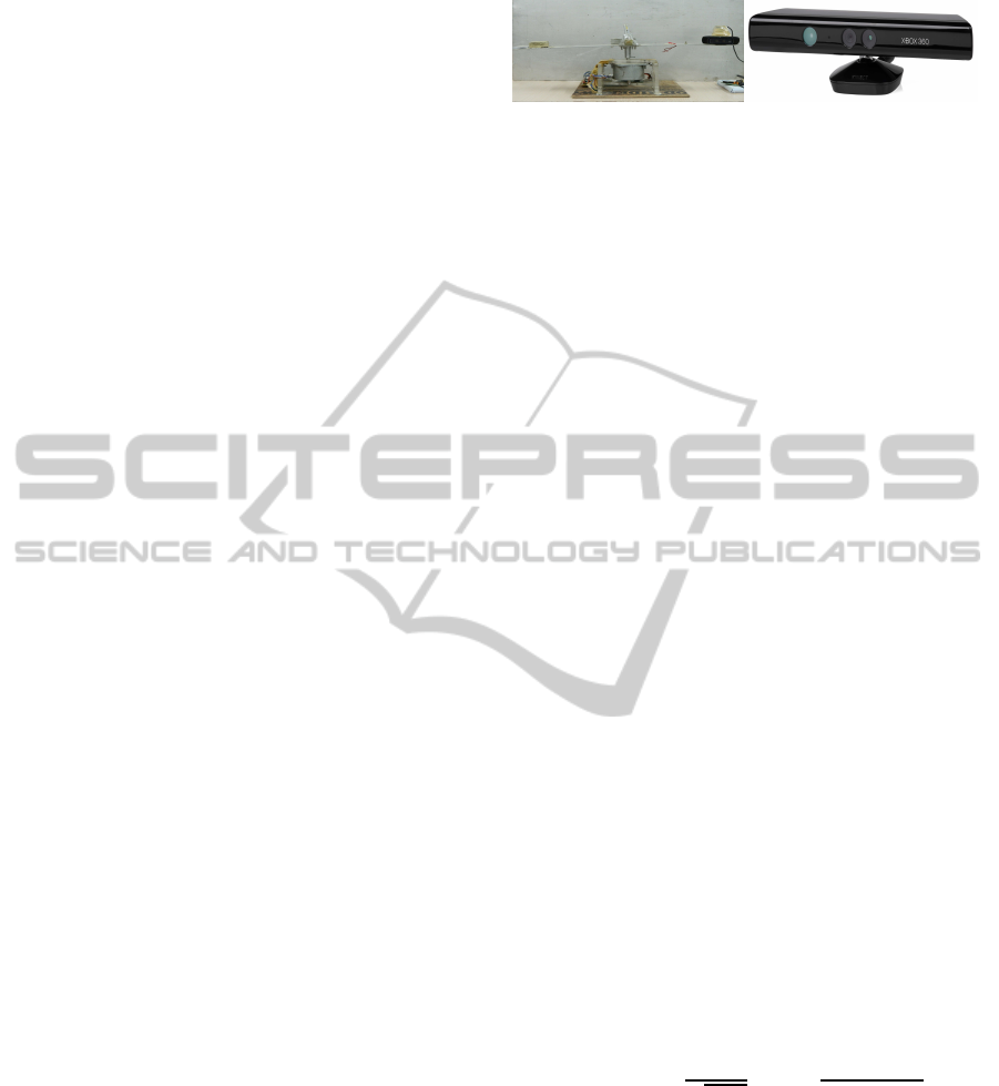
Microsoft Kinect. The figure 1(a) shows the Laser
range scanner which is deigned at our robotics lab.
In the Laser scanner system, the Laser projects laser
line on the plane and camera captures the laser line
profile. When range scanner moves over the object
surface, the camera acquires images of the distorted
pattern which are reflected by the object surface. The
height of the objects are obtained by taking into ac-
count the distortion of the laser light stripe caused
by their shapes. The designed Laser range scanner
gives accurate range measurements of the large an-
gular field with angular resolution 0.1125
0
. The ac-
curacy of the range scanner is approximately ±2-3
mm throughout its range. The major advantage of de-
signed range scanner: it gives accurate result, very
high angular resolution, no correspondence issue be-
cause the camera acquires the illuminated scene to
obtain the dense 3D geometric information in a sin-
gle exposure. The disadvantage is its high scanning
time due to sequentially scan the terrain. The fig.1(b)
shows the Kinect sensor that was introduced in Nov
2010 by Microsoft for the Xbox-360 video game sys-
tem. The detail description of Microsoft Kinect is de-
scribed in the papers (Zhang, 2012; Khoshelham and
Elberink, 2012). In(Khoshelham and Elberink, 2012),
the authors have investigated the accuracy and resolu-
tion of Kinect depth data for indoor mapping applica-
tions. They have presented that the random error of
depth measurement increase quadratic-ally with in-
creasing the distance from the sensor and it ranges
from few millimeters up to 4 cm at the maximum
range of the sensor. For the mapping application, the
working range should be within 1-3 meter distance
(a) (b)
Figure 1: (a) Laser Range sensor designed at our robotics
lab (b) The Microsoft Kinect system.
from the sensor otherwise the quality of data is dete-
riorated by noise and low resolution.
2.2 RGB-D Segmentation
In this section, we describe the method to unsu-
pervised segmentation of RGB-D images using new
framework of GMM using by employing convex re-
laxation approach.
2.2.1 Gaussian Mixture Model and EM
Algorithm
A Gaussian mixture model is a probabilistic model
that presumes all the sample points are generated
from a mixture of a fixed number of Gaussian distri-
butions with unknown parameters. Therefore a Gaus-
sian mixture model is a weighted sum of M Gaussian
component densities of x which is a D-dimensional
measurement vector as given by the equation,
p(x/µ
i
,σ
i
) =
N
∑
i=1
ω
i
g
x;µ
i
,σ
2
i
(1)
where ω denote the mixture ratio, p is the Gaus-
sian pdf parameterized by mean µ
i
and variance σ
2
.
Given data, the parameters Θ =
ω,µ,σ
2
can be ef-
ficiently estimated through maximum likelihood es-
timation (MLE) using the EM algorithm, then clus-
ters will be obtained through estimated parameters.
The log-likelihood function for GMM is given by
(McLachlan and Krishnan, 2007)
L (Θ) =
Z
Ω
log
N
∑
i=1
ω
i
√
2πσ
i
exp
(
−
[ f(x) −µ
i
]
2
2σ
2
i
)
dx
(2)
we drive the conclusion from EM algorithm that the
E-step and M-step can guarantee L
Θ
t+1
≥ L (Θ
t
)
during the updating process (i.e. t → t+1), which de-
notes the local convergence of the EM algorithm.
2.2.2 GMM using Convex Relaxation Approach
In this section, we present GMM algorithm us-
ing a convex relaxation approach. The optimiza-
tion of logarithm and summation function like
RangeDataFusionforAccurateSurfaceGenerationfromHeterogeneousRangeScanners
445

equation (2) is difficult task because the opera-
tions of these functions are not non-commutative.
However, the solution of these function could
be achieved by adding a convex relaxation term.
(u,v) represent the a vector valued function such
as v(x) = (v
1
(x),v
1
(x),v
3
(x).......v
N
(x)) and ∆ =
v|0 < v
i
< 1,
∑
N
i=1
v
i
= 1
. The symbol ∆ is defined
as the convex relaxation term for non binary vector
space (v) =
v|v
i
= {0, 1},
∑
N
i=1
v
i
= 1
. For commu-
tativity of log-sum function, we have used a deduction
of convex analysis (Rockafellar, 1997)
Lemma 1. The Log-sum Commutativity operations of
given a function α
i
(x) > 0, for any function β
i
(x) > 0,
we have
−log
N
∑
i=1
α
i
(x)exp[−β
i
(x)] = min
v(x)∈∆
(
N
∑
i=1
[β
i
(x) −α
i
(x)]v
i
(x)
+
N
∑
i=1
v
i
(x)logv
i
(x)
)
(3)
Now we set
ω
i
√
2piσ
i
= α
i
(x),
kf(x)−µ
i
k
2
2σ
2
i
= β
i
(x) and
apply lemma in equation (2). The optimization prob-
lem becomes
ˆ
Θ = argmax
Θ
L (Θ) = −argmin
Θ
L (Θ)
= argmin
θ
{
Z
Ω
min
v(x)∈∆
(
N
∑
i=1
[β
i
(x) −logα
i
(x)]v
i
(x)
+
N
∑
i=1
v
i
(x)logv
i
(x)
)
dx} (4)
Now we introduce a functional
ˆ
ε(Θ,v) with two vari-
ables Θ,v.
ˆ
ε(Θ,v) =
Z
Ω
N
∑
i=1
kf(x) −µ
i
k
2
2σ
2
−log
ω
i
√
2πσ
i
v
i
(x)dx
+
Z
Ω
N
∑
i=1
v
i
(x)logv
i
(x)dx (5)
Then we compute the minimizer of
ˆ
ε(Θ,v) via the
following alternating algorithm:
v
t+1
= argmin
u∈ξ
ˆ
ε
Θ
t
,v
Θ
t+1
= argmin
Θ
ˆ
ε
Θ,v
t+1
(6)
Where t = 1,2... is the iteration number and Θ
0
is an
initial guess.
2.2.3 The Basic Model
Now we consider the non-uniform intensity problem
because Kinect sensor capture the RGB-D images
of unstructured terrain, which can be mathematically
modeled as:
f(x) = γ(x)g(x) (7)
where g(x) is the ground truth image, f (x) refers the
observed data and γ(x) refers to a smooth varying bias
field. From (Li et al., 2008), we have taken assump-
tions that the bias field is non-negative and smoothly
varying. In the nearest neighborhood circle centered
at x i.e. γ(y) = γ(x), for all y ∈O
x
.
Here we describe method in (Li et al., 2008) with
statistical interpretation. Let us first focus on the
neighborhood O
y
centered at y , all the intensity f(y)
within neighborhood O
y
have same pfd p(x) with
the parameter µ
i
,σ
2
i
,β(y). If we deal with different
contributions to the cost functional ε(Θ,v) in terms
of distance to centering point, then we consider to
add some weights for each pixel. We have taken
the Gaussian function with std σ, G
σ
(x) ≈ 0 when
x 6∈ O
y
. Therefore, integral domain of O
y
is expanded
to whole domain Ω. i.e.,
ε
y
(Θ) = −
Z
Ω
G
σ
(y−x)log
N
∑
i=1
ω
i
√
2πσ
i
exp
(
−
[ f (x) −µ
i
]
2
2σ
2
i
)
dx
(8)
For the desirable segmentation result, we have
taken the global information and the total cost func-
tional becomes
ε(Θ) =
Z
Ω
ε
y
(Θ)dy (9)
The segmentation problem can be solve by the mini-
mization problem
Θ = argmin
Θ
ε(Θ) (10)
However, the above optimization problem is very dif-
ficult to solve due to the presence of the log-sum func-
tion. As a result, we construct the above cost function
with two variables mention in previous section. Ac-
cording to lemma 1, the final data term becomes
ˆ
ε(Θ,v) =
1
2
Z
Ω
Z
Ω
N
∑
i=1
G
σ
(y−x)
kf(x) −µ
i
k
2
2σ
2
−log
ω
i
√
2πσ
i
v
i
(x)dxdy
+
Z
Ω
N
∑
i=1
v
i
(x)logω
i
(x)dx +
1
2
Z
Ω
N
∑
i=1
v
i
(x)logσ
2
i
dx
+
Z
Ω
logβ(y)dy+
Z
Ω
N
∑
i=1
v
i
(x)logv
i
(x)
2
dx
(11)
we have to minimize
ˆ
ε(Θ,v) under the constraint
v ∈ ∆ to get the optimized v
∗
,Θ
∗
. Inspired by (Wang
ICINCO2015-12thInternationalConferenceonInformaticsinControl,AutomationandRobotics
446

et al., 2009), we have introduced another regulariza-
tion term which is guarantee the precise close-form
solution of v. The regularization term define as
R (v) =
Z
Ω
N
∑
i=1
v
i
(x)e(x)
Z
N(x;η)
[1−v
i
(y)]dydx (12)
where e is the edge detector function, N(x;η)give the
neighborhood centered at x with radius η. In the pa-
per, we take e =
1
1+k▽G
σ
∗fk
. Therefore combining the
data term and regularization term, we introduce our
new model as follows
(Θ
∗
,v
∗
) = arg min
Θ,v∈∆
L :=
ˆ
ε(Θ,v) + λR (v) (13)
where λ > 0 is a regularization parameter that con-
trols the trade-off between these two function. The
parameter set Θ becomes
Θ =
ω
1
...ω
N
,,µ
1
...µ
N
,σ
2
1
...σ
2
N
[
y
{β(y)}
(14)
This new model is inherently different from clas-
sical GMM. Firstly, the classical GMM is very sen-
sitive to noise and lacks in spatial smoothness con-
straint while the above new model has a controlling
parameter that makes it robust to noise. Secondly,
the data term in traditional GMM is only works well
for images that have almost piece-wise constant and
it can not handle the images with non-uniform inten-
sity. However, the new model incorporates local bias
function information, global intensity and edges in-
formation. Therefore, it works well on the images
with non-uniform intensity. The minimizing eq. (15),
starting from a given initial value Θ
0
such that
u
t+1
= argmin
u∈ξ
L
Θ
t
,v
Θ
t+1
= argmin
Θ
L
Θ,v
t+1
(15)
The stopping criteria of above proposed method is
kL
t
−L
t+1
k
2
< δk L
t
k
2
. In this way, we segment the
RGB-images obtained from Kinect. Now our aim to
correlate the segmented the RGB-images to their cor-
responding Depth images. For calibration of as dis-
cussed in (Herrera et al., 2012), the calibration of
Depth and the color image pair is done using planar
surface and a simple checkerboard pattern. The same
calibration method is used to establish the relation be-
tween two range sensors. After calibration, we can
easily locate the objects in the environment.
2.3 Data Fusion
The time cost of data acquisition from Laser range
scanner is high, but it provides a very high quality
range data i.e. 2 mm precision throughout the range.
On the other hand the random depth error in Kinect
(Khoshelham and Elberink, 2012) increases with in-
creasing distance from the sensor, but it is low cost,
compact range sensor and very fast relative to de-
signed Laser range sensor. The terrain characteristic
is determine in terms of surface elevation. The finer
regions of terrain are determined as the regions whose
elevation is greater than 4 cm. Therefore, the thresh-
old criterion for finer regions is determined in terms
of elevation. We use Kinect to scan the coarser re-
gions of terrain and the finer regions are scanned from
a Laser range scanner. Since the range data obtain
from both the range scanners are in different coordi-
nate systems. Thus, it is necessary to transform both
the range data into a common referenceframe. We ap-
ply the Principal component analysis (PCA)(Jolliffe,
2005) to both range data sets that orthogonality trans-
form the data set to the new coordinate system such
that the largest variance of the data is defined as first
coordinate (i.e. first principle component) and so on.
This new coordinate system is defined as a common
reference frame. Both range data are transformed
into this reference coordinate system. With the help
of segmented depth data, we find their correspond-
ing points in the transformed reference frame. The
finer detailed regions are identified in the reference
frame. Now we apply the ICP algorithm (Elseberg
et al., 2012) to align both the data set in this frame.
This alignment of the two heterogeneous range data
in reference frame is much faster than alignment of
the range data in different coordinate system. Based
on a threshold criterion, we fuse the finer region of
data which is obtained from Laser range scanner to
Kinect’s coarser regions data. The fused range data
eliminate the demerits of the range scanners by com-
plementing each other. To generate the surface, we
apply the Delaunay algorithm to the fused range data.
In this way, we reconstruct the accurate, realistic sur-
face of the terrain.
3 EXPERIMENTAL RESULTS
The proposed fusion method is tested on real world
data by creating different types of environment in our
lab. In the experiment, we have used the two hetero-
geneous Laser range scanner and Kinect shown in Fig
(1). The purpose of the range data fusion is to gen-
erate the accurate, realistic, and a fast 3D surface of
the terrain and eliminates the demerits of both range
scanners by complementing each other. In the experi-
ments, two range data sets of the same environment
are obtained from both scanners (i.e. Laser range
scanner and Kinect). First Kinect captures the RGB
RangeDataFusionforAccurateSurfaceGenerationfromHeterogeneousRangeScanners
447
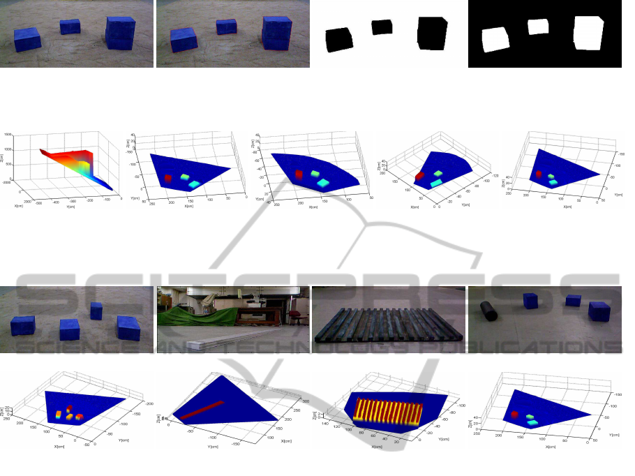
(a) (b) (c) (d)
Figure 2: (a) Figure of different types of object placed in plane (b) Active contour map (c) Segmented blocks of RGB image
and(d) Corresponding depth image.
(a) (b) (c) (d) (e)
Figure 3: (a) The 3D surface of plane isobtained from Kinect (b) After applying ICP algorithm the aligned surface from Kinect
and (c) from Laser range scanner (d) The Segmented fine region of surface from Laser range scanner (e) The accurately fused
3D surface model from both range sensors.
(a) (b) (c) (d)
(e) (f) (g) (h)
Figure 4: (a) Figure of different objects are placed on sandy plane (b) Figure of rectangular aluminum log (c) The plywood
board consist of several stick’s is placed (d) The different objects are placed (e) Shows the fused accurate 3D model of different
objects (f) Shows the fused 3D model of aluminum log (g) Shows the fused 3D surface of plywood board (h) Shows the fused
3D surface of different objects.
and Depth image of the environment. The Fig 2(a)
shows the RGB-image, The Fig 2(b) shows the ac-
tive contour with new approach of GMM and Fig 2(c)
shows the segmented objects in the image. To estab-
lish the relation between rgb image and depth image,
we have used the calibration method given by (Her-
rera et al., 2012). The Fig 2(d) shows the segmented
objects in the depth image. The finer regions of terrain
are defined as the points of range data whose elevation
is greater than 4 cm which is the threshold criterion.
The range data acquired from both the range sensors
are in different coordinate system. Therefore, it is
necessary transform both range data into one common
reference frame. We transform the both range data to
a new coordinate system such that new set of uncorre-
lated variables axis, called principle components. The
axis’s of common reference frame are defined as the
largest variance after transformation of data set to first
coordinate system and so on. The figure 3(b-c) shows
the aligned 3D surface of the terrain after applying the
ICP algorithm. The alignment of both range data in
the common reference frame using ICP algorithm is
much faster than directly apply the ICP algorithm for
alignment of the range data in two different frames.
We have defined the threshold for selecting fine re-
gion based on height data variation. Since Laser scan-
ner time cost is high, therefore we have scanned the
finer region of terrain using Laser scanner based on
segmented depth data obtained from Kinect and rest
regions are taken from Kinect i.e. we have retained
the coarser detailed regions and erase the fine detailed
region of Kinect range data. Now we have fused fine
region range data acquired from Laser scanners to
the coarser regions range data obtained from Kinect.
Using Delaunay algorithm, we have generated sur-
face of the terrain. The Fig. 3(e) shows the finally
fused surface. In 3D fusion experiment, the relative
sensor disparity of Laser range sensor relative to the
Kinect in the reference frame is as the rotation matrix
R=[ 0.9704 0.2418 0;-0.2418 0.9704 0; 0 0 1.0000];
ICINCO2015-12thInternationalConferenceonInformaticsinControl,AutomationandRobotics
448

and translation vector t=[119.4117 127.9851 0]. The
alignment root mean square error of the fused data is
approximately 3.2 mm. Many range data fusion ex-
periments have been performed with different objects
in the environment. Fig 4(a) shows the different kind
of objects place in the plane and its accurate fused 3D
terrain model is shown in Fig 4(e). Again the rectan-
gular aluminum log is placed in plane as shown in Fig
4(b) and its fused terrain model is shown in Fig 4(f).
Similarly, now we place the plywood board that has
15 rectangular log and different objects in the plane
as Fig. 4(c-d). Fig. 4 (g-h) shows the accurately fused
3D model of the terrain. The resulting fused surface
shows, the proposed method is applied to accurately,
realistically and rapidly represent the real-world envi-
ronment.
4 CONCLUSIONS
In this paper, we have presented a new approach for
range data fusion from two heterogeneous range scan-
ners (i.e. Laser range scanner and Microsoft Kinect)
in order to integrate the merits of both scanners for
the generation of accurate, realistic surface of the ter-
rain. First, we have presented a new framework of
the GMM using convex relaxation approach for seg-
mentation of RGB-D images having inhomogeneous
intensity. After transforming both the range data to
common reference frame, we have applied the ICP
algorithm to align these range data. The alignment
method of two different range data in a common refer-
ence frame is much faster than directly apply the only
ICP algorithm to their scanner coordinate system. In
the fusion process, we have selected the coarser de-
tailed region from Kinect and finer region from Laser
scanner. The fused surface of the terrain is recon-
structed using the Delaunay triangulation algorithm.
In this way, we have generated a seamless integra-
tion of the terrain surface from two overlapping range
data. The experimental results have shown the accu-
rate 3D model of terrain from fused range data. The
alignment rms error of the fused data has approxi-
mately 3-5 mm. So the main contribution of this pa-
per is to present a range data fusion approach that
eliminates the limitation of both the range sensors and
generate the accurate surface modeling of rough and
highly unstructured terrain.
REFERENCES
An, S.-Y., Lee, L.-K., and Oh, S.-Y. (2012). Fast incremen-
tal 3d plane extraction from a collection of 2d line
segments for 3d mapping. In Intelligent Robots and
Systems (IROS), 2012 IEEE/RSJ International Con-
ference on, pages 4530–4537. IEEE.
Elseberg, J., Magnenat, S., Siegwart, R., and N¨uchter,
A. (2012). Comparison of nearest-neighbor-search
strategies and implementations for efficient shape
registration. Journal of Software Engineering for
Robotics, 3(1):2–12.
Herrera, C., Kannala, J., Heikkil¨a, J., et al. (2012). Joint
depth and color camera calibration with distortion cor-
rection. Pattern Analysis and Machine Intelligence,
IEEE Transactions on, 34(10):2058–2064.
Johnson, A. E. and Manduchi, R. (2002). Probabilistic
3d data fusion for adaptive resolution surface genera-
tion. In 3D Data Processing Visualization and Trans-
mission, International Symposium on, pages 578–578.
IEEE Computer Society.
Jolliffe, I. (2005). Principal component analysis. Wiley
Online Library.
Khoshelham, K. and Elberink, S. O. (2012). Accuracy and
resolution of kinect depth data for indoor mapping ap-
plications. Sensors, 12(2):1437–1454.
Kl¨aß, J., St¨uckler, J., and Behnke, S. (2012). Efficient mo-
bile robot navigation using 3d surfel grid maps. In
Robotics; Proceedings of ROBOTIK 2012; 7th Ger-
man Conference on, pages 1–4. VDE.
Lai, K., Bo, L., Ren, X., and Fox, D. (2011). A large-
scale hierarchical multi-view rgb-d object dataset. In
Robotics and Automation (ICRA), 2011 IEEE Interna-
tional Conference on, pages 1817–1824. IEEE.
Li, C., Kao, C.-Y., Gore, J. C., and Ding, Z. (2008). Min-
imization of region-scalable fitting energy for image
segmentation. Image Processing, IEEE Transactions
on, 17(10):1940–1949.
Newcombe, R. A., Davison, A. J., Izadi, S., Kohli, P.,
Hilliges, O., Shotton, J., Molyneaux, D., Hodges,
S., Kim, D., and Fitzgibbon, A. (2011). Kinectfu-
sion: Real-time dense surface mapping and tracking.
In Mixed and augmented reality (ISMAR), 2011 10th
IEEE international symposium on, pages 127–136.
IEEE.
Rockafellar, R. T. (1997). Convex analysis. Number 28.
Princeton university press.
Singh, M. K., Venkatesh, K., and Dutta, A. (2014). Accu-
rate 3d terrain modeling by range data fusion from two
heterogeneous range scanners. In India Conference
(INDICON), 2014 Annual IEEE, pages 1–6. IEEE.
Trevor, A. J., Rogers, J., and Christensen, H. I. (2012).
Planar surface slam with 3d and 2d sensors. In
Robotics and Automation (ICRA), 2012 IEEE Inter-
national Conference on, pages 3041–3048. IEEE.
Wang, J., Ju, L., and Wang, X. (2009). An edge-weighted
centroidal voronoi tessellation model for image seg-
mentation. Image Processing, IEEE Transactions on,
18(8):1844–1858.
Wheeler, M. D., Sato, Y., and Ikeuchi, K. (1998). Con-
sensus surfaces for modeling 3d objects from multiple
range images. In Computer Vision, 1998. Sixth Inter-
national Conference on, pages 917–924. IEEE.
Zhang, Z. (2012). Microsoft kinect sensor and its effect.
MultiMedia, IEEE, 19(2):4–10.
RangeDataFusionforAccurateSurfaceGenerationfromHeterogeneousRangeScanners
449
