
Toward a Human-like Locomotion: Modelling Dynamically Stable
Locomotion of an Anthropomorphic Robot in Simulink Environment
Ramil Khusainov, Ilya Shimchik, Ilya Afanasyev and Evgeni Magid
Intelligent Robotic Systems Laboratory (LIRS), Innopolis University
40-42 Profsoyuznay str., Kazan, Republic of Tatarstan, Russian Federation
Keywords:
Anthropomorphic Robot, Biped Robot Locomotion, Dynamic Stability, Modelling, Simulink.
Abstract:
In the near future anthropomorphic robots will turn into an important part of our everyday routine. To suc-
cessfully perform various tasks these robots require stable walking control algorithms, which could guarantee
dynamic balance of the biped robot locomotion. Our research is focused on the development of locomotion
algorithms which could provide effective anthropomorphic walking of a robot. As a target robotic platform
we utilize an experimental model of a human-size robot - a novel Russian robot AR-601M. In this paper we
introduce AR-601M robot and present a model of a biped robot with 11 DoF which simulates a simplified
AR-601M robot. The simulation model is implemented in Matlab/Simulink environment and uses walking
primitives in order to provide a dynamically stable locomotion.
1 INTRODUCTION
In the last century robotics was mainly the focus of
interest of Ministries of Defense and Space, univer-
sity research laboratories and a few giant corpora-
tions. One of the most critical tasks was to develop
multi-terrain robots in order to operate in danger-
ous environments (e.g., nuclear, chemically or bio-
logically polluted environments) and to perform var-
ious functions in order to support humans in search
and rescue operations, military and space missions.
Today robotic products are rapidly turning into con-
sumer’s goods - yet not affordable and available to
all groups of the population. But that is just a ques-
tion of time, and in the coming decades we will see
the wide-spread of domestic, social and educational
robots. Such robotic systems will replace people in
various operations in unfriendly environments and at
home, and thus require comparable to a human skills
of locomotion inside buildings together with the abil-
ity to operate the devices which were originally cre-
ated for a human. To guarantee the comparable to
a human skills, multi-functionality and flexibility, an
anthropomorphic structure of a robot would be re-
quired. Bipedal locomotion of an anthropomorphic
robot provides mechanisms to step over obstacles,
climb stairs and ladders, and walk on uneven terrain
- the activities which could not be fully performed by
a wheeled or a tracked robot. Anthropomorphic do-
mestic robotic assistants would also facilitate human-
robot interactions and social activities, which often
require the robot to work in a direct physical contact
with a person, to master safe (Amirabdollahian et al.,
2013) and acceptable by a human social behavior, and
to be visually acceptable by a human (Fink, 2012).
Therefore anthropomorphic robotic systems with sta-
ble anthropomorphic movement dynamics and high-
energy efficiency become critical. During the decades
of bipedal locomotion research a number of different
approaches targeting for stable locomotion were de-
veloped, and Section 3 presents a brief overview of
the existing approaches. Unfortunately, due to seri-
ous difficulties with balance preserving and redundant
degrees of freedom (Wu et al., 2009), walking of hu-
manoid robots is still far from achieving a comparable
to a human level of anthropomorphism and reliabil-
ity (Wright and Jordanov, 2014).
The objectives of our research are to develop solu-
tions of dynamically stable walking for a biped robot
AR-601M. In order to reduce the time of software de-
velopment with the real robot and to provide system
debugging on early stages of algorithm development,
it is essential to create a relevant simulation model
which takes into an account physical properties of the
robot and its interaction with the environment. Dy-
namical mathematical models for legged locomotion
- for animals (Ijspeert, 2008), insects (Holmes et al.,
2006) or humans (Zajac et al., 2003) - help to simu-
141
Khusainov R., Shimchik I., Afanasyev I. and Magid E..
Toward a Human-like Locomotion: Modelling Dynamically Stable Locomotion of an Anthropomorphic Robot in Simulink Environment.
DOI: 10.5220/0005576001410148
In Proceedings of the 12th International Conference on Informatics in Control, Automation and Robotics (ICINCO-2015), pages 141-148
ISBN: 978-989-758-123-6
Copyright
c
2015 SCITEPRESS (Science and Technology Publications, Lda.)
late the balance-based locomotion algorithms behav-
ior prior to experiments with a robot and also may
give clues on ”healthy” or ”pathological” gaits. In
this paper we introduce current stage of our study and
present the simulation model of the biped robot AR-
601M in Matlab/SimMechanics
1
.
The rest of this paper is organized as follows. Sec-
tion 2 introduces Russian humanoid robot AR-601M.
Section 3 considers the theoretical background of a
biped robot locomotion methods. Section 4 presents
a designed Simulink model of AR-601M robot. Fi-
nally we conclude and discuss the future steps of our
research in Section 6.
2 SYSTEM SETUP
This section describes the AR-601 robot as the holis-
tic system setup, which is used for dynamically stable
robot locomotion model development.
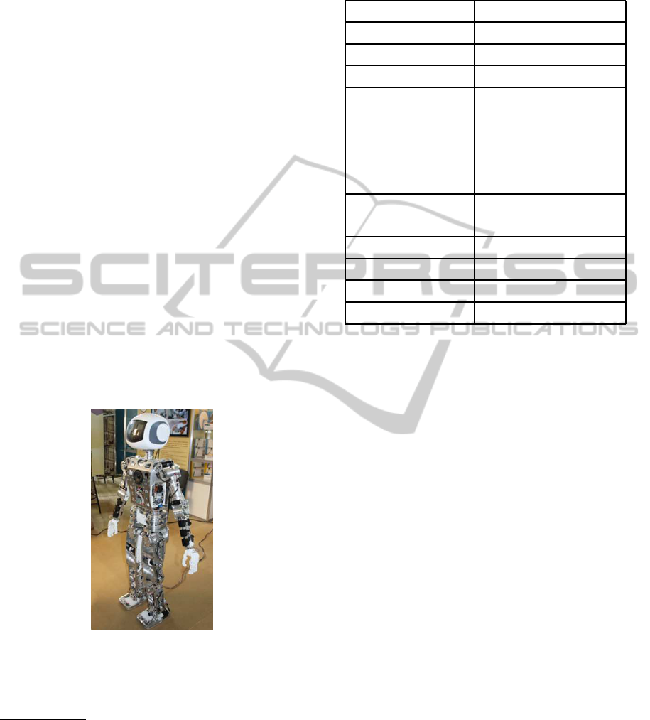
The anthropomorphic robot AR-601M (fig. 1) is
being developed by Russian company ”Android Tech-
nics”
2
. It is a full-scale anthropomorphic robot sys-
tem with the height of 144 cm and the weight of 60 kg,
which correspond well with an average human body
parameters
3
.
Figure 1: Testing anthropomorphic robot AR-601M, the
shell is removed.
The robot has a lightalloy frame with power elec-
tric motors, two robotic arm-manipulators and two
1
Multibody Simulation - SimMechanics, http://
www.mathworks.com/products/simmechanics/
2
Androidnaya Tehnika (Android Technics), AR-601M be-
longs to a generic AR-600 series of robots, http://en.npo-
at.com/products/ar-600/
3
In human robot interaction in order to maintain a clear
master-slave relationship between the two parties it is impor-
tant that a robot is not emitting any kind of threat to a human
and this requirement is particularly embodied in lower than an
average human height of the robot.
Table 1: Technical characteristics of AR-601 robot.
Parameter Value
Height 1442 mm
Mass 60 kg
Battery life 3 hours
Sensors IR × 16
Camera × 3
Lidar × 2
Accelerometer × 6
Magnetic encoder × 30
Degrees of freedom Total: 69
Active: 45
Type of Motors Electrical
Material of body Plastic
Battery type Li-FePo
Network interfaces Wi-fi, Ethernet
legs, which allows having up to 69 degrees of free-
dom (DoF), of which six DoFs belong to each leg.
To control the robot movement there are 26 large and
12 small electric motors with STM32F103T8U6 con-
trollers and the communication protocol provides data
about all motor states, pressure values in robot’s feet
and on-board gyroscopes. The robot has a built-in
multi-sensor system, speech recognition and synthe-
sis systems. Table 1 presents in details some of the
important parameters of AR-601M which influenced
our model and algorithms development.
The robot locomotion control is carried out by set-
ting the joint angles for motor’s rotation along with
angular velocities and accelerations. In addition, each
joint could be controlled directly with torque out-
put commands. Therefore, MATLAB Simulink can
be used to reproduce an interface of communications
protocol and simulate on-board robot control system
and input signals to control electric motors. To do this
within the Simulink model, simulated signal packages
are sent to the motors in synchronous mode and the
controllers manage the response packages from sen-
sors. Furthermore, it makes possible to set the coef-
ficients of the PID controller with specially simulated
commands or even to simulate the particular com-
mands like, for example, the brake coupling for fix-
ing the drives position with knee and hip joints lock-
ing. However, in common case, it is sufficient to set
the rotation angles for each joint and ignore particular
mechanisms of motor control.
ICINCO2015-12thInternationalConferenceonInformaticsinControl,AutomationandRobotics
142

3 ON BIPEDAL ROBOT
LOCOMOTION MODELLING
This section familiarizes the reader with popular mod-
els of biped robot locomotion modelling and methods
for robot motion control.
3.1 A Bipedal Robot Model
The widely utilized strategies for simulating a biped
robot are to use a model of inverted pendulum with or
without a spring.
For Inverted pendulum or linear inverted pen-
dulum model a biped robot acts as an inverted pen-
dulum, because the center of mass (CoM) of the robot
is localized in the upper body part. When the biped
robot is doing a step, its swinging leg is similar to an
inverted pendulum whose massless rod connects the
supporting foot to the CoM of the robot (Stephens
and Atkeson, 2009). As an illustration, this ap-
proach had evolved in the following models: virtual
height inverted pendulum model, two masses inverted
pendulum model, multiple masses inverted pendu-
lum model, gravity compensated inverted pendulum
model, etc. (Siciliano and Khatib, 2008)
Spring loaded inverted pendulum model is one
of the best and simplest approximation that describes
the spring-like leg behavior of human and animal
walking or running (Garofalo et al., 2012). Spring
loaded inverted pendulum is represented by a point
mass that is attached to a massless spring with resting
length and leg stiffness.
The important question is what approaches to the
biped robot locomotion control should be applied in
order to supply energy efficiency and acceptable loco-
motion speed while maintaining stability of the robot.
Next, we briefly describe a number of methods, which
are broadly applied for biped robot locomotion con-
trol by various research teams. According to (Manch-
ester et al., 2011) all the existing humanoid bipedal
walking robots could be roughly divided into two
groups: ZMP-controlled ones and passive-dynamic
walkers.
3.2 Approaches for Bipedal Robot
Locomotion Control
Zero moment point (ZMP) is a theoretical model of
biped locomotion where ZMP is defined as a point
in which all the forces and moments can be replaced
with a single force and a single moment respec-
tively (Vukobratovic and Borovac, 2004). In other
words this method defines a special point where the
sum of horizontal inertial and gravitational forces
equals to zero (Erbatur and Kurt, 2006). In order
to maintain biped robot balance its ZMP should lie
within the boundaries of a predefined stability region.
This approach plays a role of a criterion in the stabil-
ity analysis of biped robot locomotion and could be
considered as a dynamic analogue of CoM or center
of gravity (CoG) criterion for static stability analy-
sis (Magid et al., 2011). ZMP approach defines tra-
jectory of robot bodies without considering the load
of each particular joint which causes poor energy ef-
ficiency of the locomotion.
Passive walking method is based on the body’s
momentum. A biped robot which is actuated by this
method usually does not have any motors that pro-
duce forces for leg motion and the robot walks on an
inclined slope without applying any force (McGeer,
1990). It is rather efficient for controlling robot loco-
motion because it creates movements in a similar way
a human does, but due to low stability for external
disturbances, this approach is not broadly used (Iribe
and Osuka, 2006).
Walking primitives is an approach which gener-
ates trajectories for the joints. Usually walking prim-
itives are calculated offline a-priori and next locomo-
tion planning algorithm generates a sequence of mo-
tions as a combination of these predefined walking
primitives(Denk and Schmidt, 2003) in order to move
from the current posture and location to the goal lo-
cation. The main assumption in this approach is that
before and after applying a walking primitive acceler-
ations and velocities of all joints are equal to zero, and
therefore zero moment point always resides within a
support polygon (Magid et al., 2008). As an example,
a walking primitive can be realized by replacing the
center of pressure from one leg to another. In order
to combine two walking primitives together the initial
state of the second primitive should be the end state
of the previous one. This requirement is referred as a
precondition and a post-condition of a walking prim-
itive. Concatenating together several walking primi-
tives is used to generate locomotion of a biped robot.
This paper applies walking primitivesapproach which
is further described in Section 4.
Artificial neural networks approach is used to
learn the nonlinear dynamics of biped robot loco-
motion using a neuroadaptive control algorithm and
the robot achieves optimization criterion of dynamic
balance, such as ZMP. Given approach is broadly
used - for example, Boston Dynamics uses this ap-
proach for Atlas robot locomotion algorithms (Atmeh
et al., 2014). Major drawback of neural networks that
makes them less practical for real-time control ap-
plications are the exponential growth of the number
of parameters as a large-scale system becomes more
TowardaHuman-likeLocomotion:ModellingDynamicallyStableLocomotionofanAnthropomorphicRobotinSimulink
Environment
143

complicated.
Full-body posture goal approach to path plan-
ning for humanoid robots computes dynamically-
stable, collision-free trajectories from full-body pos-
ture goals (Kuffner et al., 2001). This method per-
forms a search through configuration space of the
robot in order to find a collision-free path to the goal
posture while keeping dynamic balance.
Dimension reduction techniques serve for re-
ducing calculation time: as a robot should make a
decision on a next state within a limited time, a sig-
nificant calculation time may become a reason of an
algorithm’s failure. Thus reducing dimension of lo-
comotion equations directly influences feasibility of a
locomotion algorithm. Those techniques decrease di-
mension of variables, which are used in the equations
that describe control algorithms of a robot or even
could reduce the number of such equations (Stilman
et al., 2005).
4 MODELLING A STABLE BIPED
ROBOT LOCOMOTION IN
SIMULINK
Simulations became an important tool in robotics re-
search. It helps to create advanced designs, eval-
uate new control algorithms and investigate a wide
range of solutions for complicated problems. Sig-
nificant advantage of such simulations is that there
is no need of constructing or modifying a real robot,
whereas simulated design solutions and experimental
conditionsdepend only on researcher’screativity. Nu-
merous software solutions for modeling multi-body
dynamical systems have been created specially for
robotic simulations, such as Gazebo
4
, V-Rep
5
, Mat-
lab/Simulink and others. The later provides efficient
tools for modeling and simulating mechanical sys-
tems (e.g., SimMechanics tool) which save significant
time and effort for researchers. SimMechanic uses the
standard Newtonian dynamics differential equations
and simulates 3D translational and rotational motion
by predicting the future state of a system from the
current state. SimMechanics has a great number of
tools to specify geometry, trajectories, mass distribu-
tion, constraints and instruments to initiate and mea-
sure motion, providing quite simple modeling of an
anthropomorphic robot (bodies, joints, and external
forces).
The equations of motion of a multibody system
4
http://gazebosim.org/
5
Coppelia Robotics, http://www.coppeliarobotics.com/
can be written in the following descriptor form:
˙q =
˜
Hv (1)
M(q) ˙v = f (t,q,v) +
˜
H
T
(q)G
T
(q,t)λ (2)
g(q,t) = 0 (3)
where t represents time, q is a vector of configuration
variables; H is a kinematic relationship matrix be-
tween the velocity variable v and ˙q so that v = H(q) ˙q
with matrix
˜
H denoting the right inverse of H; M(q)
is a mass matrix; f(t,q,v) represents the contribution
of centrifugal, Coriolis, and external forcing terms;
g(q,t) is a constraint equation and G(q,t) = ∂g/∂q
is a constraint Jacobian; λ represents the vector of
Lagrange multipliers associated with the constraint
forces (Wood and Kennedy, 2003).
In (Velasquez-Lobo et al., 2013) the authors
demonstrate an example of a biped robot model de-
sign and its locomotion verification with SimMechan-
ics tool. Their model consists of five rigid bodies:
a torso (modelled as a parallelepiped) and identical
cylindrical shanks and thighs. These bodies are con-
nected with revolute joints with a single rotational
DoF in each joint and which sum up to 4 DoF in to-
tal. Unfortunately, such model simulates only the bot-
tom part of the robot with its torso moving only in a
sagittal plane relatively to the fixed coordinate system
without rotation (2 DoF); this creates artificial condi-
tions which prevent the robot from falling down.
In this paper we present a biped robot model
which is free from the above mentioned limitations.
The following simulation steps were performed using
SimMechanics:
• Specify geometry of robot parts and their inertial
properties
• Create links between the robot part - connect the
bodies with rotational joints
• Set up ground reaction forces
• Provide reference signal for positions of each joint
• Start simulation, calling the Simulink solvers
• Visualize the model
Specifying robot geometry begins with defining a
number of links and joints. Our current simplified
robot model consists of twelve bodies, which are con-
nected with revolute joints for knees, ankles, hips (one
rotational DoF) and fixed (non-rotating) joints for a
neck, elbows and shoulders. The torso and feet have
a shape of a parallelepiped, a head is a sphere, and
all other bodies are cylinders; the body parameters are
described in details in Table 2. With regard to a global
fixed coordinate system the torso has 3 DoF in sagit-
tal plane: a rotation and 2 translations in vertical and
ICINCO2015-12thInternationalConferenceonInformaticsinControl,AutomationandRobotics
144
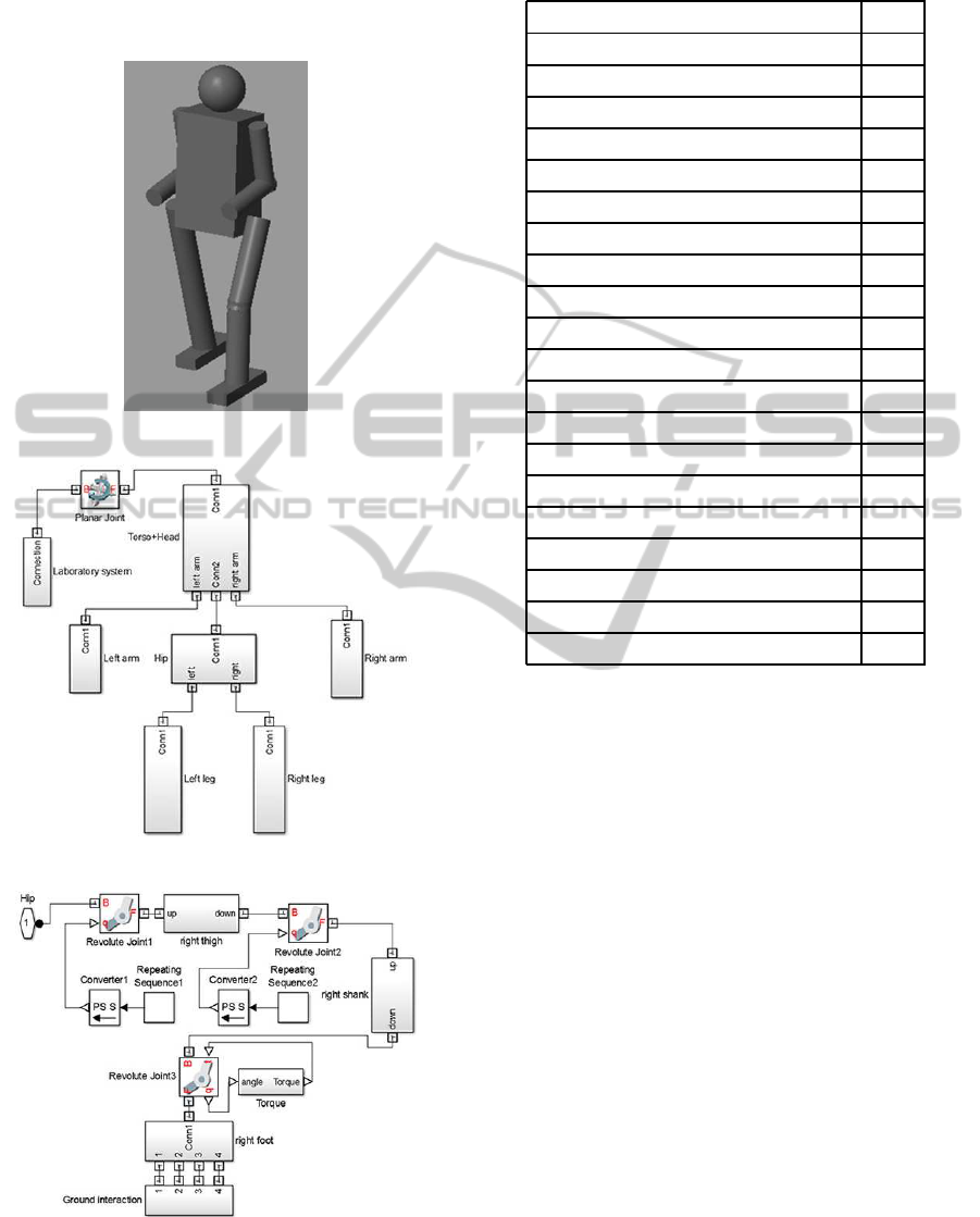
horizontal directions. Figure 2 shows the model struc-
ture. SimMechanics block diagram of the whole robot
and its leg are shown in Fig. 3 and Fig. 4 respectively.
Figure 2: The robot model in Simulink.
Figure 3: SimMechanics block diagram for the biped robot.
Figure 4: SimMechanics block diagram for the leg.
Definition of ground contact forces is a very im-
portant issue in biped robot simulation and should
Table 2: Link parameters.
Torso parameters
a, m 0.3
b, m 0.2
c, m 0.5
Mass, kg 30
Shank and Thigh parameters
R, m 0.05
Length, m 0.4
Mass, kg 3.14
Head parameters
Radius, m 0.1
Mass, kg 2.1
Upper and lower arm parameters
R, m 0.01
Length, m 0.3
Mass, kg 0.75
Foot parameters
Width, m 0.1
Length, m 0.3
Height, m 0.05
Mass, kg 1.5
be carefully modeled. When robot’s feet touch the
ground, normal and tangential forces are applied.
There are several different approaches to calculate
these forces. In the current work foot-ground interac-
tion was modeled through a linear system with damp-
ing and stiffness. The following equation represents
normal forces:
F
n
= −k
n
y− b
n
˙y (4)
where y is the coordinate of the leg tip (y=0 corre-
sponds to ground surface), k
n
in the elastic constant
and b
n
is the damping coefficient. Normal force ap-
plied only when y ≤ 0 (i.e. when the leg touches the
ground). In order to avoid leg sticking F
n
is limited to
positive values only.
The following equation represents tangential
force:
F
t
= −b
t
˙x (5)
where b
t
is the tangential damping coefficient. Simi-
larly to normal force, tangential force is applied only
when y ≤ 0. The ground coefficients k
n
,b
n
,b
t
should
be large (Table 3) in order to guarantee acceptable
small penetrations of feet below ground level (the re-
sponsible for penetration coefficient is k
n
) and reason-
ably fast damping of contact velocity (the responsi-
ble for damping coefficients are b
n
,b
t
). Equation 5
TowardaHuman-likeLocomotion:ModellingDynamicallyStableLocomotionofanAnthropomorphicRobotinSimulink
Environment
145
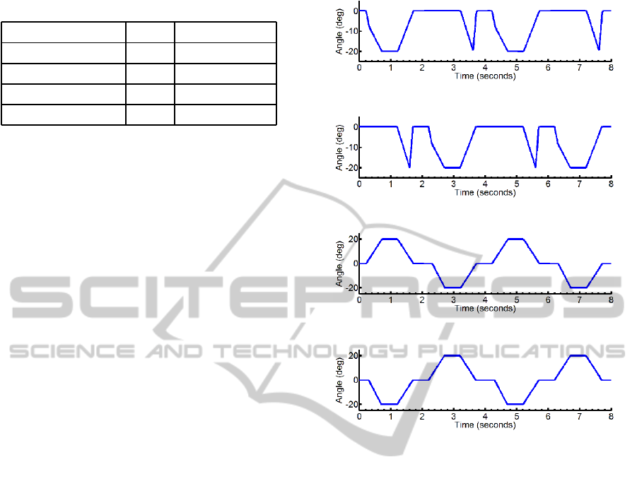
Table 3: Ground parameters (coefficients).
Coefficient Label Value / Units
penetration k
n
1000000 N
normal damping b
n
10000 (N*s)/m
tangential damping b
t
1000 (N*s)/m
friction µ 10
works perfect at leg landing, whereas at leg raising a
so-called sticking effect emerges: we cannot provide
strict vertical movement and have a horizontal com-
ponent of velocity, which results in large tangential
force. To avoid this sticking effect, the absolute value
of tangential force should be limited to µF
n
, where µ
is a friction coefficient. At leg landing normal force
F
n
value is large, so the tangential force will be large
enough to prevent the robot from sliding. At leg rais-
ing normal force F
n
is small enough to avoid sticking.
As far as the robot moves only in sagittal plane, there
are no contact forces in
~
Z direction.
There are several ways in SimMechanics to ac-
tivate robot locomotion. The simplest one is to set
positions of revolute joints. SimMechanics module
calculates necessary torques to achieve desired angles
in joints at each time step. These nominal trajectories
can be set up a-priori, e.g., by utilizing motion capture
system. In our work we realized dynamically stable
robot motion using the method of walking primitives
described in Section 3.2. It means that robot move-
ment is divided into identical periods with walking
primitives, at the beginning and at the end of which
the robot returns to the same position. The leg move-
ment pattern is the same in each primitive and can be
divided into four phases (assuming generically that
the step primitive starts from the left foot): (1) lift
the left foot by specifying desired angles for hip and
knee joints; (2) perform the inverted pendulum mo-
tion until the left foot touches the ground; (3) move
the right foot forward by specifying the joint angles
which make the knee and the hip joint angles equal to
zero; (4) damp forward motion by applying torque in
the ankles. Next, the same phases are repeated start-
ing the step from the right leg. The input signals for
the knee and thigh joint positions of the robot’s legs
are shown in Fig. 5– 8.
In the last walking phase the robot’s forward mo-
tion is damped by applying torque in ankles when
hip and knee joint angles become zero. The value of
torque is calculated according to the following equa-
tion:
T = −cφ − d
˙
φ (6)
where φ is the ankle joint angle, c=10 is stiffness, d=4
is the damping coefficient. Equation 6 is a standard
Figure 5: The input angle for the right knee.
Figure 6: The input angle for the left knee.
Figure 7: The input angle for the right hip.
Figure 8: The input angle for the left hip.
representation of damping oscillations. As far as os-
cillations cannot be damped simultaneously, a pause
△t is required before starting new movement with an-
other leg.
5 SIMULATION RESULTS
To solve differential equations described above, the
Simulink solver method ”ODE 23t” was used. Fig. 9
shows a sequence of the biped robot frames at differ-
ent time while performing a single step. The smooth
character of simulated robot walking illustrates rea-
sonable settings for the angle positions of the joints
and contact forces within the model. The horizontal
locomotionof the torso center with the mean robot ve-
locity of 0.3-0.4 m/s is shown in Fig. 10, demonstrat-
ing the periodical body movement during two second
time period. At the beginning of each motion period
the body velocity is zero. Torque values in the hip
and the knee joints obtained from the simulation are
shown in Fig. 11-14, which help to estimate motor
characteristics.
The simulation shows that maximum torque is ap-
proximately 500 N*m in the thigh joint and 300 N*m
ICINCO2015-12thInternationalConferenceonInformaticsinControl,AutomationandRobotics
146
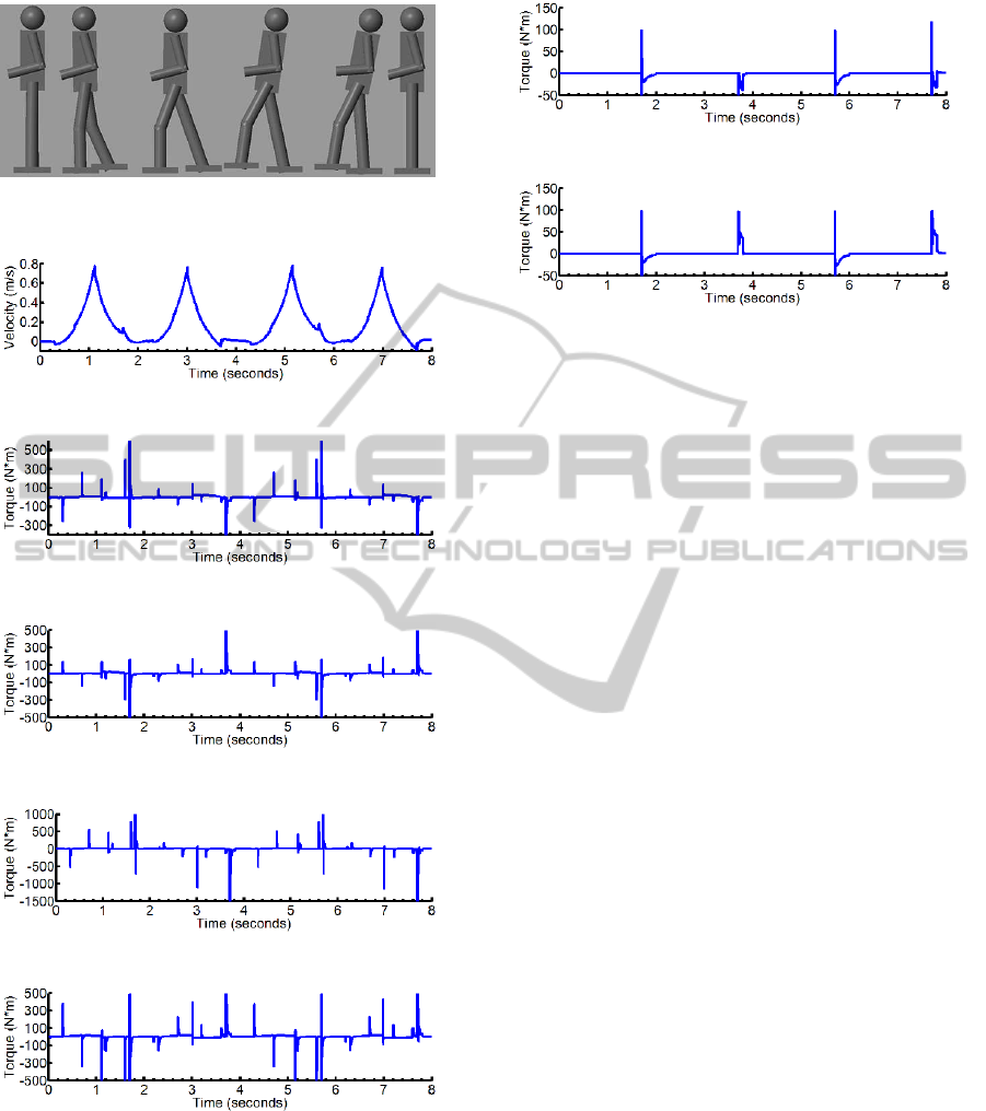
Figure 9: A single step of the biped robot. The robot moves
from right to left as the time passes.
Figure 10: Horizontal velocity of torso.
Figure 11: Torque in the left knee.
Figure 12: Torque in the right knee.
Figure 13: Torque in the left hip.
Figure 14: Torque in the right hip.
in the knee joint. At the same time we see discon-
tinuous jumps in calculated torque values, which are
caused by discontinuities in ground reaction forces.
Torque values in ankles are shown in Fig. 15 and
Fig. 16. As it was expected, torque is applied only
in the last phase of robot’s motion in order to damp
robot’s movement. In our work the duration of one
Figure 15: Torque in the left ankle.
Figure 16: Torque in the right ankle.
walking primitive is 2 seconds with a pause of
△t = 0.5 seconds between the primitives.
6 CONCLUSIONS AND FUTURE
WORK
Our research is focused on creating effective hu-
man like locomotion for the novel anthropomorphic
human-size Russian robot AR-601M. In this paper
we introduced AR-601M biped robot, and presented
its simplified model with 11 DoFs. The simulation
model has been implemented in Matlab/Simulink us-
ing SimMechanics tool. This model uses walking
primitives in order to provide a dynamically stable lo-
comotion and serves as a starting point for the stable
bipedal locomotion algorithms development for the
AR-601M robot. The smooth character of simulated
robot walking with the mean velocity of 0.3-0.4 m/s,
reasonable settings for the angles of joints and contact
forces illustrates the suitability of the proposed robot
model.
Next we are going to extend this simplified model
by increasing the number of DoFs (i.e. the num-
ber of robot joints) in order to match the simulation
robot model to the exact kinematic structure of AR-
601M. To achieve AR-601M anthropomorphic walk-
ing, the human walking data will be acquired and
analyzed by Motion Capture (MoCap) system with
the key features detection for a human gait. They
will be initially mapped to the AR-601M locomotion
within Matlab/Simulink simulation and then into the
real robot gait together with the adaptive gait genera-
tion algorithm with the ZMP control. To apply these
algorithms with a real robot it is also required to de-
velop algorithms for sensory data collection and pro-
cessing; in turn, these modules will provide input for
decision-making and control actions computation al-
gorithms.
TowardaHuman-likeLocomotion:ModellingDynamicallyStableLocomotionofanAnthropomorphicRobotinSimulink
Environment
147

ACKNOWLEDGEMENTS
This research has been supported by Russian Min-
istry of Education and Science as a part of Sci-
entific and Technological Research and Develop-
ment Program of Russian Federation for 2014-2020
years (agreement 14.609.21.0004, research grant
ID RFMEFI60914X0004) and by Android Technics
company, the industrial partner of the research.
REFERENCES
Amirabdollahian, F., Dautenhahn, K., Dixon, C., Eder, K.,
Fisher, M., Koay, K., Magid, E., Pipe, T., Salem, M.,
Saunders, J., and Webster, M. (2013). Can you trust
your robotic assistant? In 5th International Confer-
ence in Social Robotics. Springer.
Atmeh, G., Ranatunga, I., Popa, D., Subbarao, K., Lewis,
F., and Rowe, P. (2014). Implementation of an adap-
tive, model free, learning controller on the atlas robot.
In IEEE American Control Conference.
Denk, J. and Schmidt, G. (2003). Synthesis of walk-
ing primitive databases for biped robots in 3d-
environments. In IEEE International Conference on
Robotics and Automation.
Erbatur, K. and Kurt, O. (2006). Humanoid walking robot
control with natural zmp references. In IEEE Annual
Conference on Industrial Electronics.
Fink, J. (2012). Anthropomorphism and human likeness in
the design of robots and human-robot interaction. In
Social Robotics. Springer.
Garofalo, G., Ott, C., and Albu-Schaffer, A. (2012). Walk-
ing control of fully actuated robots based on the
bipedal slip model. In IEEE International Conference
on Robotics and Automation.
Holmes, P., Full, R., Koditschek, D., and Guckenheimer, J.
(2006). The dynamics of legged locomotion: Models,
analyses, and challenges. Siam Review, vol. 48(2).
Ijspeert, A. J. (2008). Central pattern generators for loco-
motion control in animals and robots: a review. In
Neural Networks.
Iribe, M. and Osuka, K. (2006). A designing method of
the passive dynamic walking robot via analogy with
the phase locked loop circuits. In IEEE International
Conference on Robotics and Biomimetics.
Kuffner, J., Nishiwaki, K., Kagami, S., Inaba, M., and In-
oue, H. (2001). Motion planning for humanoid robots
under obstacle and dynamic balance constraints. In
IEEE International Conference on Robotics and Au-
tomation.
Magid, E., Ozawa, K., Tsubouchi, T., Koyanagi, E.,
and Yoshida, T. (2008). Rescue robot navigation:
static stability estimation in random step environment.
In Simulation, Modeling, and Programming for Au-
tonomous Robots. Springer Berlin Heidelberg.
Magid, E., Tsubouchi, T., Koyanagi, E., and Yoshida, T.
(2011). Building a search tree for a pilot system of a
rescue search robot in a discretized random step envi-
ronment. In Journal of Robotics and Mechatronics.
Manchester, I., Mettin, U., Iida, F., and Tedrake, R. (2011).
Stable dynamic walking over uneven terrain. In
The International Journal of Robotics Research. Sage
Publications.
McGeer, T. (1990). Passive dynamic walking. In The Inter-
national Journal of Robotics Research, vol.9(2).
Siciliano, B. and Khatib, O. (2008). Biped robots in the zmp
scheme. In Springer Handbook of Robotics. Springer.
Stephens, B. and Atkeson, C. (2009). Modeling and control
of periodic humanoid balance using the linear biped
model. In IEEE-RAS International Conference on Hu-
manoid Robots.
Stilman, M., Atkeson, C., Kuffner, J., and Zeglin, G.
(2005). Dynamic programming in reduced dimen-
sional spaces: Dynamic planning for robust biped lo-
comotion. In Robotics Institute, vol.73.
Velasquez-Lobo, M., Ramirez-Cortes, J., Rangel-
Magdaleno, J., and Vazquez-Gonzalez, J. (2013).
Modeling a biped robot on matlab/simmechanics.
In IEEE International Conference on Electronics,
Communications and Computing.
Vukobratovic, M. and Borovac, B. (2004). Zero-moment
point - thirty five years of its life. In International
Journal of Humanoid Robotics, vol.1(1).
Wood, G. D. and Kennedy, D. C. (2003). Simulating
mechanical systems in simulink with simmechanics.
Tech. Rep., The MathWorks.
Wright, J. and Jordanov, I. (2014). Intelligent approaches
in locomotion - a review. Journal of Intelligent and
Robotic Systems.
Wu, Q., Liu, C., Zhang, J., and Q.Chen (2009). Survey of
locomotion control of legged robots inspired by bio-
logical concept. Science in China Series F: Informa-
tion Sciences, vol.52(10).
Zajac, F. E., Neptune, R. R., and Kautz, S. A. (2003).
Biomechanics and muscle coordination of human
walking: part ii: lessons from dynamical simulations
and clinical implications. Gait and posture, vol.17(1).
ICINCO2015-12thInternationalConferenceonInformaticsinControl,AutomationandRobotics
148
