Visual Syntax of UML Class and Package Diagram Constructs as an
Ontology
Anitta Thomas
1
, Aurona J. Gerber
2,3
and Alta van der Merwe
2
1
School of Computing, University of South Africa, The Science Campus, Florida Park, South Africa
2
Department of Informatics, University of Pretoria, Pretoria, South Africa
3
Center for Artificial Intelligence Research (CAIR), CSIR Meraka, Pretoria, South Africa
Keywords:
Visual Syntax Specification, UML Class Diagrams, UML Package Diagrams, OWL, Ontology, Ontology
Reasoner, Prot´eg´e.
Abstract:
Diagrams are often studied as visual languages with an abstract and a concrete syntax (concrete syntax is
often referred to as visual syntax), where the latter contains the visual representations of the concepts in the
former. A formal specification of the concrete syntax is useful in diagram processing applications as well as
in achieving unambiguous understanding of diagrams. Unified Modeling Language (UML) is a commonly
used modeling language to represent software models using its diagrams. Class and package diagrams are two
diagrams of UML. The motivation for this work is twofold; UML lacks a formal visual syntax specification
and ontologies are under-explored for visual syntax specifications. The work in this paper, therefore, explores
using ontologies for visual syntax specifications by specifying the visual syntax of a set of UML class and
package diagram constructs as an ontology in the Web ontology language, OWL. The reasoning features of
the ontology reasoners are then used to verify the visual syntax specification. Besides formally encoding the
visual syntax of numerous UML constructs, the work also demonstrates the general value of using OWL for
visual syntax specifications.
1 INTRODUCTION
The prevalence of diagrams in our day-to-day lives
has led to much research interest in studying diagrams
(Peter Cheng and Haarslev, 2000). Formal specifica-
tions of the syntax and semantics of diagrams are con-
sidered valuable in promoting unambiguous under-
standing of diagrams between humans andcomputers,
and computers and computers (Marriott et al., 1998).
As a knowledge representation tool, ontologies have
been successfully used to model domain knowledge
(Wyner and Hoekstra, 2012). However an investiga-
tion of the current literature indicates a gap in the use
of ontologies for the concrete syntax specification of
diagrams. This work tries to address this gap by ex-
ploring the use of ontologies for the concrete syntax
specification of diagrams.
The concrete syntax of a visual language describes
the visual layout of the diagrams that are part of
the language (Drewes and Klempien-Hinrichs, 2000),
where diagrams may have both graphical and textual
elements (Marriott et al., 1998) (Minas, 2006). This
syntax is essential for describing the visual language
(Minas, 2006) and it can be useful for applications
that support the automated generation and interpre-
tation of diagrams in such visual languages (Marriott
et al., 1998) (Minas, 2006). Such applications are par-
ticularly useful for visually impaired users who rely
on text instead of graphics for understanding and gen-
erating diagrams.
Unified Modeling Language (UML) is a visual
language that uses both text and graphical elements
(uml, 2012a). Class and package diagrams are two
types of UML diagrams (Moody and van Hillegers-
berg, 2009) used to represent a static structure of an
object oriented model (uml, 2012b). The constructs
of UML are standardized with a specification, the
current version being UML 2.4.1 (uml, 2012a) (uml,
2012b). Although UML 2.4.1 specification includes
the syntax and semantics of its constructs, it lacks a
formal representation of the visual syntax of its dia-
grams. Evidence of this lack is that the concrete syn-
tax (hereafter referred to as visual syntax) of UML
constructs is specified as textual descriptions of ac-
cepted notations along with sample figures only (uml,
2012a) (uml, 2012b). The lack of a formal visual syn-
Thomas, A., Gerber, A. and Merwe, A..
Visual Syntax of UML Class and Package Diagram Constructs as an Ontology.
In Proceedings of the 7th International Joint Conference on Knowledge Discovery, Knowledge Engineering and Knowledge Management (IC3K 2015) - Volume 2: KEOD, pages 17-28
ISBN: 978-989-758-158-8
Copyright
c
2015 by SCITEPRESS – Science and Technology Publications, Lda. All rights reserved
17
tax representation is another motivation for consider-
ing UML class and package diagrams for visual syn-
tax specification in this work.
A drawback with a lack of formal visual syntax
specification is that even UML compliant tools could
generate UML diagrams differently, which can cause
confusion when users interpret them (Elaasar and
Labiche, 2011). As a visual representation tool, the
visual syntactical structure of UML diagrams should
be consistent irrespective of the tools that generated
it. The use of a formal visual syntax specification in
UML tools is one way to ensure consistent rendering
of its diagrams. Moreover, given that non-compliant
UML tools can also generate visually valid UML di-
agrams, such tools can also make use of a formal vi-
sual syntax specification to promote consistent view
of these diagrams.
Numerous techniques in different formalisms
such as grammatical, logical and algebraic have been
used for visual syntax specifications. Within the log-
ical formalism, Description Logics (DL) have also
been explored for visual syntax specifications (Mar-
riott et al., 1998). Although DL have influenced
the Web ontology language, OWL, (Horrocks et al.,
2003), the use of OWL ontologies itself for visual lan-
guage specifications is under-explored.
Given the fact that ontologies are under-explored
for visual syntax specifications and UML lacks a for-
mal visual syntax representation, the work in this pa-
per addresses these gaps by specifying the visual syn-
tax of selected constructs of UML class and package
diagrams as an OWL ontology. In particular, it spec-
ifies the visual syntax of a selected number of UML
constructs that are typically used in class and package
diagrams (uml, 2012b). The reasoning features of the
ontology reasoners are then examined to see how they
can be utilized to verify such a visual syntax specifi-
cation.
The contribution of this research is threefold; it
provides a formal encoding of the visual syntax of se-
lected UML class and package diagram constructs, it
explores OWL for visual syntax specifications and it
explores the value of OWL reasoners to verify visual
syntax specifications. The latter two aspects entail
a generic contribution to the field of visual language
specification.
This paper is structured as following: section 2
provides background information to the work pre-
sented in the paper. This includes a brief introduction
to the research on visual languages, UML class and
package diagram constructs used in this paper, OWL
and qualitative spatial relationships used in this paper.
Section 3 briefly presents related work to this research
study. Section 4 describes the visual syntax ontology,
which is the visual syntax specification of the selected
UML class and package diagram constructs. Section
5 explores the reasoning features of the ontology rea-
soners that can be used to verify the visual syntax
specification given in section 4. A possible enhance-
ment for the developed visual syntax specification is
discussed in section 6. Section 7 concludes with a
summary, a reflection and the value of this work, and
future research.
2 BACKGROUND
This section includes brief background information
on various topics covered in this paper and places this
work within the existing work on visual languages.
2.1 Visual Languages
In Computer Science (CS), diagrams are studied as vi-
sual languages, where diagrams in a given visual lan-
guage follow a common syntactical structure (Drewes
and Klempien-Hinrichs, 2000). When studying a vi-
sual language in CS, researchers are faced with two
main tasks; symbolic specification of its visual syntax
and semantics in a suitable formalism, and the study
of the use of such specifications in technical applica-
tions (Marriott et al., 1998). The work in this paper
only focuses on the specification of the visual syntax
of a selected set of UML class and package diagram
constructs.
Although the visual syntax specification pre-
scribes the visual structure of valid diagrams, more
than one correct specification is possible for a given
visual language. These variations occur because a
spatial structure can be modeled in different ways
(G Costagliola and Tortora, 1997) based on the cho-
sen spatial relationships and the granularity of primi-
tive elements. Thus in view of these variations there
can be numerous visual syntax specifications for a vi-
sual language like UML.
Numerous techniques in grammatical, logical, al-
gebraic formalisms have been explored for visual lan-
guage specifications. Such specifications have also
been used in numerous diagram processing applica-
tions as well. The paper by (Marriott et al., 1998) in-
cludes an overview of the various visual syntax spec-
ification techniques and applications. The specifica-
tion formalism used in this work is logic with ontol-
ogy as the specification technique.
KEOD 2015 - 7th International Conference on Knowledge Engineering and Ontology Development
18
2.2 UML Class and Package Diagram
Constructs
UML is a widely used modeling language for repre-
senting software models (Moody and van Hillegers-
berg, 2009), overseen by the standards consortium
Object Management Group (OMG) (uml, 2012a).
UML provides thirteen diagrams (Moody and van
Hillegersberg, 2009) for representing structural and
dynamic aspects of software systems (Javed et al.,
2005) and it can be used in the design, analysis, im-
plementation and documentation of software applica-
tions (uml, 2012b) (uml, 2012a). UML has an interna-
tionally accepted standard (uml, 2012b) (uml, 2012a)
that specifies its syntax and semantics.
UML class and package diagram constructs are
specified in the Classes package of the UML 2.4.1
specification. Classes package includes fifty six con-
structs that can be used to represent an object ori-
ented (OO) model using class, package and object
diagrams. These UML constructs include both OO
constructs (example: Class) as well as non-OO con-
cepts (example: Comment). Some of these UML con-
structs are represented exclusively using text (exam-
ple: MultiplicityElement), some using only graphi-
cal elements (example: Generalization) and majority
uses both graphical and text elements (example: In-
terface). Some UML constructs do not have their own
distinct notations (example: DirectedRelationship) as
the notations are meant to be defined using specializa-
tions of these constructs (example: ElementImport)
(uml, 2012b).
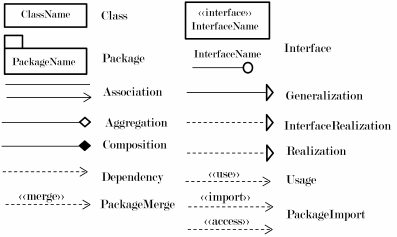
The set of UML class and package diagram con-
structs that are considered in this work are Class, In-
terface, Package, Association, Aggregation, Compo-
sition, Dependency, Generalization, Usage, Realiza-
tion, InterfaceRealization, PackageMerge and Pack-
ageImport. These thirteen constructs were chosen be-
cause they are the typical constructs used in class and
package diagrams and similarly the notations consid-
ered are the notations used for these constructs as in-
dicated on pages 147 to 150 in the UML 2.4.1 spec-
ification (uml, 2012b). Based on these selected nota-
tions, Association, Interface and PackageImport have
two notations each while the other ten constructs have
one notation each. Figure 1 lists the UML constructs
and their notations (uml, 2012b) used in this paper.
The chosen notations are not the only notations
for the selected UML constructs. For example a
Class can be represented using a rectangle with three
compartments and additional strings to represent data
members and methods in addition to the class name.
However, such variations are intentionally excluded
from this paper to limit the scope of the notations.
Figure 1: A subset of UML class and package diagram
constructs and their respective notations considered in this
work.
2.3 OWL
OWL is a prominent ontology language (Motik et al.,
2008) for the Semantic Web (Parreiras and Staab,
2010). OWL makes use of DL for its logical founda-
tions, which allow reasoners to infer aspects based on
what is specified in an ontology (Motik et al., 2008).
Ontologies are used for knowledge representation in
numerous disciplines such as biology, medicine, ge-
ography, astronomy and agriculture (Motik et al.,
2008).
An OWL ontology models a domain using classes,
properties, instances and data values (Horrocks et al.,
2012). A class represents a set of objects, a prop-
erty describes a possible relationship between objects,
instances describe the objects themselves and a data
value links an instance to a specific data type (Hor-
ridge et al., 2009). OWL provides a rich set of con-
structs such as union, intersection and negation to de-
scribe classes and characteristics such as transitivity,
symmetry and reflexivity to describe properties. Due
to the compositional nature of OWL, complex classes
can be described using other classes in the ontology
(Horridge et al., 2009) (Parreiras and Staab, 2010).
An ontology reasoner can be used to check the
correctness as well as to infer new knowledge based
on what is described in the ontology. In other words,
it helps in detecting inconsistencies in the ontology
as well as maintaining the class hierarchies by infer-
ence based on the explicitly stated information in the
ontology. The automated reasoning capabilities of an
ontology reasoner are vital in maintaining correct on-
tologies (Horridge et al., 2009).
There are numerous OWL ontology development
editors (examples include Prot´eg´e and SWOOP) and
reasoners (examples include HermiT, RacerPro and
Pellet) available (Bock et al., 2008). This work uses
Prot´eg´e as the ontology development editor and Her-
miT as the ontology reasoner.
Visual Syntax of UML Class and Package Diagram Constructs as an Ontology
19
2.4 Spatial Relationships
A spatial layout can be described using spatial rela-
tionships between objects in a given space. Spatial
relationships can be classified into categories of direc-
tion, distance, topology, alignment and size (Zhang,
2007). A spatial relationship in general can be de-
scribed qualitatively without any reference to the
quantitative (example: geometric) information that is
required to establish these relationships (Renz, 2002).
In this study spatial relationships are expressed quali-
tatively with the assumption that the mapping of these
relationships to the quantitative information or vice
verse is dealt separately, which is beyond the scope of
this paper.
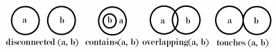
In this work four topological relationships, dis-
connected, contains, overlapping and touching, are
used to describe the spatial relationship between two
visual objects (Zhang, 2007). A visual object x can be
described using three sets of points: a set of interior
points I(x), a set of boundary points B(x) and a set
of all its points D(x) = I(x) ∪ B(x). Then for two vi-
sual objects a and b the four topological relationships
mean the following:
• disconnected(a, b) iff D(a) ∩ D(b) =
/
0 (Zhang,
2007)
• contains(a, b) iff D(b) ⊆ D(a) (Zhang, 2007)
• overlapping(a, b) iff B(a) ∩ B(b) 6=
/
0 and I(a) ∩
I(b) 6=
/
0
• touching(a, b) iff B(a) ∩ B(b) 6=
/
0 and I(a) ∩
I(b) =
/
0
The visual representations of these four spatial re-
lationships are given in figure 2 (Zhang, 2007).
Figure 2: Visual representations of four topological spatial
relationships (Zhang, 2007).
3 RELATED WORK
Numerous techniques for and applications of visual
syntax specification are reported in the literature. Ex-
amples of visual syntax specification techniques in-
clude graph grammars and DL. Visual syntax spec-
ifications have been used in technical applications
that interpret images of diagrams and drawing tools
that support users in creating syntactically correct di-
agrams (Marriott et al., 1998). The work in (Mar-
riott et al., 1998) includes a survey of different spec-
ification techniques and applications of visual syntax
specifications.
Since DL provide the logical foundations for
OWL (Motik et al., 2008), a brief summary of DL for
visual languages is included in this section. A general
DL formalism has been successfully used for the for-
mal specification of entity-relationship diagrams and
a visual programming language, Pictorial Janus (Mar-
riott et al., 1998). The visual syntax specification of
entity-relationship diagrams was then used in DL sys-
tems CLASSIC and LOOM to automate diagram rea-
soning to realize a syntax-directed diagram editor that
can validate diagrams (Haarslev, 1996). The visual
syntax of Pictorial Janus was used to formalize its se-
mantics, which was also used to realize a diagram ed-
itor that verifies the semantics of diagrams of Pictorial
Janus (Haarslev, 1995).
An investigation of the current literature indicates
a lack with regards to publications on the use of OWL
ontologies for visual syntax specifications. A visual
syntax specification in this context refers to a sym-
bolic encoding of the visual syntax of diagrams that
are part of a visual language. On the other hand
there exists ontologies that model shapes and graph-
ical concepts in general; the ontology presented in
(Niknam and Kemke, 2011) is one such ontology.
Note that such generic ontologies do not capture vi-
sual syntax of diagrams in specific visual languages.
The lack of studies exploring OWL ontologies for
visual language specification and the lack of formal
visual syntax specification for UML class and pack-
age diagram constructs, provide sufficient motivation
for this study.
4 VISUAL SYNTAX
SPECIFICATION OF UML
CONSTRUCTS
The visual syntax of the selected UML constructs is
modeled using primitive elements and spatial rela-
tions as in (Haarslev, 1996) and (Haarslev, 1995). A
discussion on the primitive elements and the spatial
relationships and how they are modeled in the OWL
ontology is included in the next two subsections, fol-
lowed by the visual syntax definitions of the thirteen
UML constructs in section 4.3.
4.1 Primitive Elements
The primitive elements for the thirteen UML con-
structs are arrow, circle, filled diamond, unfilled di-
amond, double rectangle, line, dotted line, rectan-
gle, triangle and string. The visual representations of
these ten primitive elements are illustrated in figure 3.
KEOD 2015 - 7th International Conference on Knowledge Engineering and Ontology Development
20
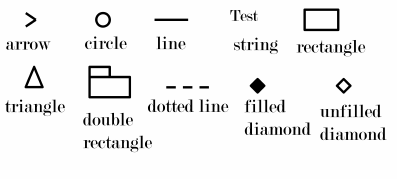
Figure 3: Primitive elements of the selected UML class and
package diagram constructs.
The ten primitive elements are modeled as ten
OWL classes namely Arrow, Circle, DiamondFilled,
DiamondUnfilled, DoubleRectangle, Line, Dotted-
Line, Rectangle, Triangle and String, as subclasses of
an OWL class Primitives.
4.2 Spatial Relationships
The four spatial relationships discussed in section 2.4
are included as object properties in the OWL ontol-
ogy. The OWL object properties disconnected, con-
tains, overlapping and touching represent these four
spatial relationships in the ontology.
4.3 UML Class and Package Diagram
Constructs
In this section, the visual syntax of the selected UML
class and package diagram constructs is specified us-
ing the primitive elements and spatial relationships
given in sections 4.1 and 4.2. The thirteen UML con-
structs are defined as thirteen OWL classes namely
UMLClass, Interface, Package, Association, Aggre-
gation, Composition, Dependency, Generalization,
Realization, InterfaceRealization, Usage, PackageIm-
port and PackageMerge. These thirteen classes are
defined as subclasses of an OWL class, UMLCon-
structs, a sibling class of Primitives (see section 4.1).
The visual syntax of the UML constructs is specified
as class definitions as given below.
4.3.1 Class
The UML construct Class is represented using a rect-
angle and a string to represent the class name. An
OWL class named UMLClass to represent this Class
construct is specified as:
Class: UMLClass
EquivalentTo:
Rectangle
and (contains some String)
4.3.2 Interface
As shown in Figure 1, an Interface can be represented
using two different notations. The first notation uses
a circle, a line and a string to represent the interface
name. The second notation is similar to that of a Class
construct except that it contains two strings. Thus the
OWL class Interface is specified as:
Class: Interface
EquivalentTo:
Line and (disconnected some String)
and (touches some Circle),
Rectangle and (contains min 2 String)
4.3.3 Package
A Package is represented using a double rectangle and
a string to represent the package name. The visual
syntax of Package is specified in the OWL class Pack-
age as given below:
Class: Package
EquivalentTo:
DoubleRectangle and (contains some String)
4.3.4 Association
Similar to the UML construct Interface, Association
also has two notations; one using a line and the other
one using a line and an open arrow. The presence
of an arrow in an association indicates navigability
while the absence of an arrow indicates undetermined
navigability between two Classes (uml, 2012b). An
OWL class named Association to specify the visual
syntax of Association is given as:
Class: Association
EquivalentTo:
Line
and (touches min 2 UMLClass),
Line and (touches some UMLClass)
and (touches some (Arrow and
(touches some UMLClass)))
Note that the definition of the class Association
makes use of the class UMLClass.
4.3.5 Aggregation
An Aggregation relationship between two
Class
es,
is represented using an unfilled diamond and a line.
Thus an OWL class named Aggregation is specified
as:
Class: Aggregation
EquivalentTo:
Line and (touches some UMLClass)
and (touches some (DiamondUnfilled
and (touches some UMLClass)))
Similar to the OWL class Association, Aggrega-
tion also makes use of the class UMLClass.
Visual Syntax of UML Class and Package Diagram Constructs as an Ontology
21
4.3.6 Composition
The UML construct Composition, a type of relation-
ship between two
Class
es, is represented using a filled
diamond and a line. Thus an OWL class named Com-
position is specified as:
Class: Composition
EquivalentTo:
Line and (touches some UMLClass)
and (touches some (DiamondFilled
and (touches some UMLClass)))
Similar to the OWL class Aggregation, Composi-
tion is also defined in terms of the class UMLClass.
4.3.7 Dependency
Dependency is represented using a dotted line and
an arrow either between two
Class
es or two
Pack-
age
s. In order to distinguish between package level
and class level dependency, two subclasses of an
OWL class Dependency namely ClassDependency
and PackageDependency are defined as follows:
Class: ClassDependency
EquivalentTo:
LineDotted and (touches some UMLClass)
and (touches some (Arrow
and (touches some UMLClass)))
SubClassOf: Dependency
Class: PackageDependency
EquivalentTo:
LineDotted and (touches some Package)
and (touches some (Arrow
and (touches some Package)))
SubClassOf: Dependency
ClassDependency and PackageDependency are
composed of the OWL classes UMLClass and Pack-
age respectively.
4.3.8 Generalization
Generalization, a type of relationship between two
Class
es, is represented using a triangle and a line.
The visual syntax of Generalization is specified in the
OWL class named Generalization as follows:
Class: Generalization
EquivalentTo:
Line and (touches some UMLClass)
and (touches some (Triangle
and (touches some UMLClass)))
Again the definition of Generalization is com-
posed of the OWL class UMLClass.
4.3.9 Realization
Realization is represented using a triangle and a dot-
ted line between two
Class
es. The visual syntax of
Realization is specified in the OWL class named Re-
alization as follows:
Class: Realization
EquivalentTo:
LineDotted and (touches some UMLClass)
and (touches some (Triangle
and (touches some UMLClass)))
Again the definition of Realization is composed of
the OWL class UMLClass.
4.3.10 InterfaceRealization
The UML construct, InterfaceRealization, is specified
between an
Interface
and a Class using a triangle and
a dotted line. Thus an OWL class named InterfaceRe-
alization is defined as:
Class: InterfaceRealization
EquivalentTo:
LineDotted and (touches some UMLClass)
and (touches some (Triangle
and (touches some Interface)))
The class definition of InterfaceRealization is also
defined in terms of the OWL classes UMLClass and
Interface.
4.3.11 Usage
Usage
is a type of Dependency represented using the
keyword use placed next to the visual representation
of Dependency. Similar to Dependency,
Usage
ex-
ists either between two Classes or between two
Inter-
face
s. Thus using the selected four spatial relation-
ships, two subclasses of an OWL class Usage namely
ClassUsage and PackageUsage are specified as fol-
lows:
Class: PackageUsage
EquivalentTo:
PackageDependency and (disconnected
some String)
SubClassOf: Usage
Class: ClassUsage
EquivalentTo:
ClassDependency and (disconnected
some String)
SubClassOf: Usage
The definitions of PackageUsage and ClassUsage
are defined in terms of PackageDependency and
ClassDependency respectively.
KEOD 2015 - 7th International Conference on Knowledge Engineering and Ontology Development
22
4.3.12 PackageImport
Similar to
Usage
, PackageImport is also a type of De-
pendency that can exist between two
Package
s. Pack-
ageImport is represented using the keyword import or
access near to the Dependency representation. Thus
using the four spatial relationships, an OWL class
named PackageImport is defined as:
Class: PackageImport
EquivalentTo:
PackageDependency and (disconnected
some String)
The definition of PackageImport is also defined in
terms of PackageDependency.
4.3.13 PackageMerge
Similar to PackageImport, PackageMerge is also a
kind of Dependency between two Packages repre-
sented using the keyword merge. The OWL class for
the visual syntax of PackageMerge is defined as the
following:
Class: PackageMerge
EquivalentTo:
PackageDependency and (disconnected
some String)
The definition of PackageMerge is also defined in
terms of PackageDependency.
Although these thirteen UML constructs were in-
dividually defined in terms of the selected primitives
and spatial relationships, no verification is performed
on the ontology. The verification of the visual syntax
of the UML constructs is discussed in the next sec-
tion.
5 REASONER FEATURES FOR
VISUAL SYNTAX
VERIFICATION
All notations illustrated in figure 1 are distinct, mean-
ing that all the selected UML constructs have dis-
tinct notations. It should be noted that even though
the notations for InterfaceRealization and Realization
are the same in figure 1, the former UML construct
connects an Interface to a Class but the latter con-
struct connects two Classes resulting in two distinct
visual representations. This distinction in notations
means that the visual syntax definitions of these con-
structs must be also distinct. In this section, various
OWL reasoner features are applied to verify the dis-
tinctness of the visual syntax definitions. This section
also highlights how various features in Prot´eg´e can be
used for visual syntax verification.
5.1 Class Equivalence
When two OWL classes are equivalent the sets of ob-
jects represented by these classes are the same (Hor-
rocks et al., 2012). Class equivalence between two
OWL classes can be explicitly stated or inferred by
the reasoner based on the class descriptions. In the
context of a visual syntax ontology, identification of
equivalent classes based on its class descriptions is
significant.
When the visual syntax is specified as an OWL
ontology, class equivalence can be used to check
whether the syntax definitions of any two visual con-
structs are the same. If two OWL classes are inferred
to be equivalent based on its definitions, it means that
the syntax definitions are not distinct. When a dis-
tinct mapping is required between a visual language
concept and its visual syntax, then class equivalency
is not desirable. Detecting class equivalency between
two OWL classes representing two concepts that do
not have the same visual structure prompts a redefini-
tion of their visual syntax definitions.
Detecting equivalent classes, in other words, de-
tecting visual concepts with the same syntax defini-
tions can be achieved by invoking the reasoner in
Prot´eg´e, which highlights equivalent classes in the
Class hierarchy (inferred)
tab as well as in individual
class definitions specified in
EquivalentTo
descrip-
tion.
For the ontology given in section 4, three classes,
PackageImport, PackageMerge and PackageUsage
were reported to be equivalent, meaning that the syn-
tax definitions of these UML constructs are not dis-
tinct. Although this inferred equivalency is valid
based on their class definitions, it is not desired based
on the notations in figure 1. These incorrect visual
syntax definitions indicate that the selected spatial re-
lationships are not sufficient to describe the syntax
of these constructs. As the differences in these con-
structs are in the content of the strings placed next to
the graphical objects, we redefine these three OWL
classes to make use of three different data properties
of type string as given below:
Class: PackageUsage
EquivalentTo:
PackageDependency
and (disconnected some StringUse)
SubClassOf:
Usage
where the OWL class StringUse is defined as:
Visual Syntax of UML Class and Package Diagram Constructs as an Ontology
23
Class: StringUse
EquivalentTo:
hasStringValue some
xsd:string[pattern "use"]
SubClassOf:
String
Class: PackageImport
EquivalentTo:
PackageDependency
and (disconnected some
(StringAccess or StringImport))
where the OWL classes StringAccess and StringIm-
port are defined as:
Class: StringImport
EquivalentTo:
hasStringValue some
xsd:string[pattern "import"]
SubClassOf:
String
Class: StringAccess
EquivalentTo:
hasStringValue some
xsd:string[pattern "access"]
SubClassOf:
String
Class: PackageMerge
EquivalentTo:
PackageDependency
and (disconnected some StringMerge)
where the OWL class StringMerge is defined as:
Class: StringMerge
EquivalentTo:
hasStringValue some
xsd:string[pattern "merge"]
SubClassOf:
String
After the redefinitions of the OWL classes, Pack-
ageImport, PackageMerge and PackageUsage as de-
scribed above,no more equivalentclasses are reported
in the class hierarchy inferred by the reasoner.
5.2 Class Subsumption
If an OWL class A is subsumed by B, it means an in-
stance of A is also an instance of B (Horrocks et al.,
2012). Class subsumption is a reasoner service (Hor-
rocks et al., 2012), which is key in inferring the class
relationships in an OWL ontology.
Class subsumption can be used to verify the in-
ferred class hierarchy to ensure that the visual syntax
definitions in an ontology do indeed model the rela-
tionships between the modeled visual constructs cor-
rectly. For example, although both UMLClass and In-
terface use Rectangle and String, semantically a Class
is not an Interface or vice verse.
In Prot´eg´e, after invoking the reasoner on an on-
tology, the class subsumptions can be read in the
Class hierarchy (inferred)
tab as well as in the
Sub-
Class Of
section of individual class definitions.
Invoking the reasoner on the ontology in section 4,
which has been updated in section 5.1, highlights two
undesired subsumption relationships. One is where
Interface is subsumed by UMLClass and the second
one is InterfaceRealization, which is subsumed by
Realization. These two inferred subsumptions are se-
mantically incorrect for UML class diagrams since an
object cannot be an InterfaceRealization and a Real-
ization. Similarly an object, if relevant, has to be ei-
ther an Interface or a Class.
The OWL class Interface is inferred to be a sub-
class of UMLClass because the class Interface con-
tains at least 2 strings where as UMLClass contains
at least 1 string, which means the former class is
a specialization of the latter class. This subsump-
tion relationship between UMLClass and Interface
also leads to the undesired subsumption relationship
between InterfaceRealization and Realization. The
OWL class InterfaceRealization is specified in terms
of UMLClass and Interface. Since UMLClass sub-
sumes Interface, the OWL class InterfaceRealization
is inferred to be a subclass of Realization.
A possible solution to eliminate these undesired
subsumption relationships is discussed in section 5.4.
5.3 Class Disjointness
When two OWL classes are disjoint no object is com-
mon between the sets of objects represented by these
classes. Class disjointness is not a reasoner service
but an OWL class descriptor that needs to be explic-
itly stated for the classes in an ontology (Horrocks
et al., 2012).
In a visual syntax ontology, disjointness between
OWL classes is another check that can be used to en-
sure that the visual syntax definitions are distinct. It
also ensures that two disjoint visual constructs cannot
have an instance in common. If disjointness between
OWL classes results in inconsistency in OWL classes,
it will be highlighted in both the tabs Class hierarchy
and
Class hierarchy (inferred)
in Prot´eg´e.
For the ontology given in section 4, which has
been updated in section 5.1, no two classes can have a
common object except between Dependency and Us-
age, PackageImport and PackageMerge because the
KEOD 2015 - 7th International Conference on Knowledge Engineering and Ontology Development
24
latter three concepts are defined in terms of the first
concept. So, for example, an instance of PackageIm-
port can be an instance of Dependency as well. How-
ever, enforcing disjointness among the set of thirteen
OWL classes as described above highlights unsatisfi-
able definitions of the classes Interface and Interface-
Realization, which is incorrect because these are two
distinct concepts. The problem arises because of the
contradictions introduced by disjointness between In-
terface and UMLClass, and InterfaceRealization and
Realization, when subsumption relationships are in-
ferred between Interface and UMLClass, and Inter-
faceRealization and Realization.
A possible solution to eliminate these unsatisfiable
class definitions is discussed in section 5.4.
5.4 Class Satisfiability
If an OWL class is unsatisfiable then an object of the
class cannot exist (Horrocks et al., 2012). Checking
for class satisfiability is an automated reasoner ser-
vice (Horrocks et al., 2012), which can be used for
checking the correctness of the class descriptions in
an ontology.
As discussed in section 5.3, the classes Interface
and the class InterfaceRealization are not satisfiable.
Unsatisfiable classes are highlighted in red in both the
tabs Class hierarchy and
Class hierarchy (inferred)
in
Prot´eg´e.
One solution to resolve these two unsatisfiable
classes is to redefine the OWL class UMLClass as:
Rectangle and (contains min 1 (String
and not StringInterface))
where the OWL class StringInterface is defined as:
Class: StringInterface
EquivalentTo:
hasStringValue some
xsd:string[pattern "interface"]
SubClassOf:
String
This redefinition is based on the fact that an Inter-
face contains the keyword interface but a UMLClass
does not use the keyword interface (refer to figure 1).
This redefinition of UMLClass makes all classes de-
fined under UMLConstructs (see section 4.3) satisfi-
able and removes the undesired subsumption relation-
ships (described in section 5.2) between UMLClass
and Interface, and InterfaceRealization and Realiza-
tion.
5.5 Instance Checking
a is inferred to be an instance of class A if a sat-
isfies the class description of A (Horrocks et al.,
2012). Instance checking is an automated reasoner
service (Horrocks et al., 2012), which makes use of
the explicitly stated and inferred information about
the classes and instances to determine whether an in-
stance belongs to a class.
Instance checking can be used to check whether
the syntax definitions indeed capture the visual struc-
ture of concepts by comparing the instances inferred
by the reasoner to the concepts identified by a human
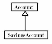
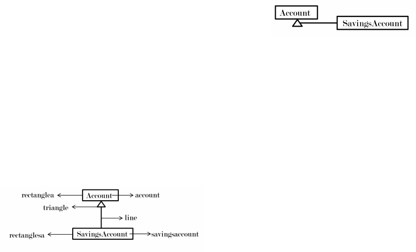
expert for a given diagram. For example, the simple
class diagram given in figure 4 depicts the UML con-
cept Class twice (Account and SavingsAccount) and
the UML concept Generalization once (relationship
between Account and SavingsAccount).
Figure 4: A sample class diagram with two UML Classes
namely Account and SavingsAccount where Account inher-
its from SavingsAccount (Generalization).
In order to check whether the reasoner infers the
UML concepts in figure 4 correctly, the UML class
diagram has to be described using the primitive ele-
ments and spatial relationships given in sections 4.1
and 4.2. Ideally one topological spatial relationship
should be specified between each pair of primitive el-
ements. However, the given list of spatial relation-
ships is not an exhaustive list of spatial relationships
for a given space. For example, the spatial relation-
ship of a visual object to itself and the spatial relation-
ship between a contained object to the container ob-
ject cannot be described using the selected four spatial
relationships. Nevertheless, the UML class diagram
in figure 4 is added to the visual syntax ontology as
follows:
Individual: account
Types: String, not (StringInterface)
Facts: disconnected savingsaccount,
disconnected rectanglesa, disconnected
triangle, disconnected line
Individual: savingsaccount
Types: String, not (StringInterface)
Facts: disconnected account,
disconnected rectanglea,
disconnected triangle, disconnected
line
Individual: rectanglea
Types: Rectangle
Visual Syntax of UML Class and Package Diagram Constructs as an Ontology
25
Facts: disconnected savingsaccount,
disconnected line, disconnected
rectanglesa, contains account,
touching triangle
Individual: rectanglesa
Types: Rectangle
Facts: disconnected account,
disconnected triangle, disconnected
rectanglea, contains savingsaccount,
touching line
Individual: line
Types: Line
Facts: disconnected account, disconnected
savingsaccount, disconnected rectanglea,
touching triangle, touching rectanglesa
Individual: triangle
Types: Triangle
Facts: disconnected account, disconnected
savingsaccount, disconnected rectanglesa
touching rectanglea, touching line
For ease of reference, the UML class diagram in
figure 5 is annotated with the relevant instance names
used in the ontology.
Figure 5: UML class diagram in figure 4 annotated with
instance names used in the ontology.
After invoking the reasoner on an ontology in
Prot´eg´e, the instances can be read in the
Class hier-
archy
in the
Members
section of individual class de-
scriptions. The
DL Query
facility in Prot´eg´e can also
be used for querying instances.
For the visual syntax ontology with the instances,
the reasoner infers two instances of UMLClass (rect-
angleA and rectangleSA) and one instance of Gener-
alization (line), which is the correct interpretation of
UML concepts for the class diagram in figure 4.
Note that the translation of figure 4 to OWL el-
ements is done manually here. This is not ideal as it
becomes cumbersome and error-prone when the num-
ber of constructs in the diagram increases. Ideally
there should be a tool that the modeler can use to draw
or import the diagram, which automatically generates
the OWL entries. An investigation of such tools is not
done for this work.
6 POSSIBLE ENHANCEMENT OF
THE UML VISUAL SYNTAX
SPECIFICATION
UML constructs generally follow accepted guide-
lines for its notations, which are not explicitly stated
in the UML specification. For example, figure 6
demonstrates an uncommon notation of Generaliza-
tion, which can be comparedto the generally followed
notation in figure 4.
Figure 6: An uncommon representation of Generalization.
The visual syntax ontology in sections 4 and 5
does not take into account such general presentation
guidelines. Thus using the developed visual syntax
ontology, the Generalization notation in figure 6 will
indeed be classified by the reasoner as an instance
of the OWL class Generalization because the trian-
gle and line are touching although it does not follow
the general presentation guideline of Generalization
where the line should touch a triangle opposite to the
point where the triangle touches the super class (here
Account). The correctness of such an instance clas-
sification of Generalization is debatable among UML
users.
A possible enhancement for the given visual syn-
tax specification is to capture such general presenta-
tion guidelines to align it closelyto the real-world rep-
resentations of UML constructs without contradicting
the UML specification.
7 CONCLUSION, REFLECTION
AND FUTURE WORK
In this work visual syntax of a subset of notations
of thirteen UML class and package constructs were
modeled using primitive graphical elements and spa-
tial relationships. As a novel approach, an OWL on-
tology was successfully used to specify the visual syn-
tax of the selected UML constructs. Furthermore it is
demonstratedthat numerous automated reasoning ser-
vices of the ontology reasoners can be used to verify
a visual syntax specification.
Based on the work presented in this paper, it can
be concluded that an OWL ontology can indeed be
used for visual syntax specification provided that the
visual constructs can be modeled using classes, prop-
erties, objects and data types as required by OWL.
The main advantage of using an OWL ontology is the
KEOD 2015 - 7th International Conference on Knowledge Engineering and Ontology Development
26
use of ontology reasoners to verify the syntax spec-
ification. Using OWL is of value because it allows
the reuse of mature software artifacts including OWL
ontology editors and reasoners for visual syntax spec-
ification.
Although this work focuses on UML as the visual
language, it is also of value to the broader field of
visual syntax specification. The process of modeling
visual constructs, specifying the visual syntax in an
OWL ontology and utilizing the ontology reasoners
as demonstrated in this work can be equally applied
to another visual language as well.
It should be noted that this work focused on a lim-
ited number of UML constructs and notations, and
hence no claim on the completeness of the visual syn-
tax can be made. Needless to say that how well the
automated reasoning features can be utilized, depends
on the number of constructs encoded in the ontol-
ogy and how the constructs are modeled. As stated
in section 2.1, the same set of UML notations can
be modeled differently, which may result in a differ-
ent visual syntax ontology. Similarly, the applications
of the given visual syntax are also not considered in
this paper. It is envisaged that a technical application
that processes the visual layout of diagrams can make
use of such a visual syntax ontology. Such applica-
tions generally perform an interpretation to produce a
literal translation or a semantic interpretation of dia-
grams. As discussed in the introduction, such appli-
cations can be valuable for visually impaired users to
improve the accessibility of diagrams.
Future research would include expanding the de-
veloped ontology to incorporate all the UML con-
cepts in the Classes package of UML specification
and general presentation guidelines (as discussed in
section 6), conducting an in-depth study of the auto-
mated reasoner services for the verification of visual
syntax specifications and analyzing the computational
efficiency of reasoning services based on the number
of classes and instances in a visual syntax ontology.
REFERENCES
(2012a). Information technology - Object Management
Group Unified Modeling Language (OMG UML), In-
frastructure. Object Management Group.
(2012b). Information technology - Object Management
Group Unified Modeling Language (OMG UML), Su-
perstructure. Object Management Group.
Bock, J., Haase, P., Ji, Q., and Volz, R. (2008). Benchmark-
ing OWL Reasoners. In van Harmelen, F., Herzig,
A., Hitzler, P., Lin, Z., Piskac, R., and Qi, G., edi-
tors, Proceedings of the ARea2008 Workshop. CEUR
Workshop Proceedings.
Drewes, F. and Klempien-Hinrichs, R. (2000). Picking
Knots from Trees: The Syntatic Structure of Celtic
Knotwork. In Michael Anderson, P. C. and Haarslev,
V., editors, Theory and Application of Diagrams, First
International Conference, Diagrams 2000, volume
1889 of Lecture Notes in Artifical Intelligence, pages
89–104. Springer.
Elaasar, M. and Labiche, Y. (2011). Diagram Definition: a
Case Study with the UML Class Diagram. In MoD-
ELS 2011, Lecture Notes in Computer Science, pages
364–378. Springer.
G Costagliola, A De Lucia, S. O. and Tortora, G. (1997).
A Framework of Syntactic Models for the Implemen-
tation of Visual Languages. In Proceedings of IEEE
Symposium on Visual Languages, pages 58–65. IEEE.
Haarslev, V. (1995). Formal Semantics of Visual Lan-
guages using Spatial Reasoning. In Visual Languages,
Proceedings., 11th IEEE International Symposium on,
pages 156–163.
Haarslev, V. (1996). Using Description Logic for Reason-
ing about Diagrammatical Notations. In L. Padgham
(Ed.) Proceedings of the International Workshop on
Description Logics, pages 124–128.
Horridge, M., Drummond, N., Jupp, S., Moulton, G., and
Stevens, R. (2009). A Practical Guide To Build-
ing OWL Ontologies Using Prot´eg´e 4 and CO-ODE
Tools. University of Manchester.
Horrocks, I., Parsia, B., and Sattler, U. (2012). OWL 2
Web Ontology Language: Direct Semantics (Second
Edition). World Wide Web Consortium.
Horrocks, I., Patel-Schneider, P. F., and van Harmelen, F.
(2003). From SHIQ and RDF to OWL: the making of
a Web Ontology Language. Web Semantics: Science,
Services and Agents on the World Wide Web, 1(1):7 –
26.
Javed, F., Mernik, M., Bryant, B. R., and Gray, J. (2005). A
Grammar-Based Approach to Class Diagram Valida-
tion. In Fourth International Workshop on Scenarios
and State Machines: Models, Algorithms and Tools
(SCESM), St. Louis, MO.
Marriott, K., Meyer, B., and Wittenburg, K. B. (1998). Vi-
sual Language Theory. chapter A Survey of Visual
Language Specification and Recognition, pages 5–85.
Springer-Verlag New York, Inc., New York, NY, USA.
Minas, M. (2006). Syntax Definition with Graphs. Electron.
Notes Theor. Comput. Sci., 148(1):19–40.
Moody, D. and van Hillegersberg, J. (2009). Evaluating
the Visual Syntax of UML: An Analysis of the Cog-
nitive Effectiveness of the UML Family of Diagrams.
In Gaˇsevi´c, D., L¨ammel, R., and Van Wyk, E., ed-
itors, Software Language Engineering, volume 5452
of Lecture Notes in Computer Science, pages 16–34.
Springer Berlin Heidelberg.
Motik, B., Cuenca Grau, B., and Sattler, U. (2008). Struc-
tured Objects in OWL: Representation and Reasoning.
In Proceedings of the 17th International Conference
on World Wide Web, WWW ’08, pages 555–564, New
York, NY, USA. ACM.
Niknam, M. and Kemke, C. (2011). Modeling Shapes and
Graphics Concepts in an Ontology. In Janna Hastings,
Visual Syntax of UML Class and Package Diagram Constructs as an Ontology
27
Oliver Kutz, M. B. and Borgo, S., editors, Proceedings
of the First Interdisciplinary Workshop on SHAPES.
Parreiras, F. S. and Staab, S. (2010). Using Ontologies with
UML Class-based Modeling: The TwoUse Approach.
Data & Knowledge Engineering, 69(11):1194 – 1207.
Special issue on contribution of ontologies in design-
ing advanced information systems.
Peter Cheng, M. A. and Haarslev, V. (2000). Preface. The-
ory and Application of Diagrams, First International
Conference, Diagrams 2000.
Renz, J. (2002). Qualitative Spatial Reasoning with Topo-
logical Information. Springer-Verlag, Berlin, Heidel-
berg.
Wyner, A. and Hoekstra, R. (2012). A Legal Case OWL
Ontology with an Instantiation of Popov V. Hayashi.
Artif. Intell. Law, 20(1):83–107.
Zhang, K. (2007). Spatial Specification. In Visual Lan-
guages and Applications, pages 37–57. Springer US.
KEOD 2015 - 7th International Conference on Knowledge Engineering and Ontology Development
28
