Cricket Catching Drills
Application of a Redundantly Actuated 2-DOF 3-UPS Parallel Platform to
Increase the Efficacy of Providing Catching Practice Drills in Cricket
Ajinkya Arun Bhole
1
and Ravi Kant Mittal
2
1
Department of Mechanical Engineering, Birla Institute of Technology and Science, Pilani, Rajasthan, India
2
K. R. Mangalam University, Gurgaon, India
Keywords: Cricket, Training, Catching Drills, Simulation and Modelling, Parallel Chain Platform.
Abstract: 'Catches win matches' is probably the oldest adage in Cricket. A fielder may only be required to take one
catch in an entire game, but his success in taking that catch may have a considerable effect on the outcome of
the match. Application of technology to sports equipment has a great impact on performance and has a
potential to revolutionize the entire sporting culture.
This paper presents an application of a redundantly actuated 2-DOF 3-UPS Parallel Chain Platform to boost
the efficacy of providing catching practice drills by maintaining a degree of realism. The basic idea is to
swerve a ball shot from a Ball Shooting Machine onto the platform, in random or desired directions by
changing the orientation of the platform instantaneously as the ball hits it. We have formulated a method to
calculate the velocity and angle of launch of the ball, required to provide practice drills for high catches and
simulated the same.
1 INTRODUCTION
Catching in Cricket requires a range of skills, some of
which include intense concentration, ability to take
quick reactions, anticipate the trajectory of the ball
and excellent athleticism. Mastering these skills
require intense practice of catching drills. To increase
the effectiveness of providing catching drills, we
thought of introducing a 2 Degree Of Freedom (DOF)
(Roll and Pitch) platform to direct a ball shot from a
Ball Shooting Machine towards the fielder. This
could pose an immediate question, Why use a 2-DOF
Platform separately along with the Ball Shooting
Machine, as using a 2-DOF Ball Shooting Machine
solely might serve the purpose? This can be answered
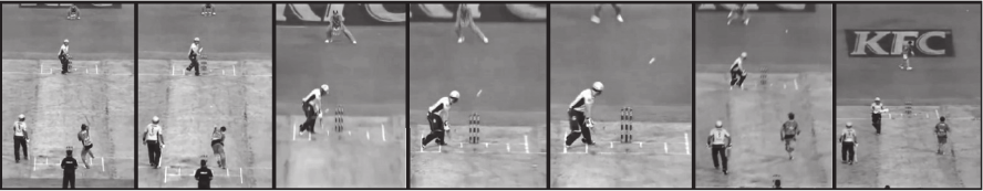
if one looks at the Late-cut shot (Figure 1) played by
Eoin Morgan (Morgan, 2014). If one observes
carefully, the wicket-keeper initially followed the ball
by anticipating its trajectory, but did not keep an eye
on the blade of the bat, and the brilliant late-cut shot
left him helpless. This is the reason why a wicket-
keeper or any fielder should always keep an eye on
the ball as it leaves the bowler as well as the blade of
the batsman's bat because they have a very small
reaction time. Using a 2-DOF Platform for practicing
catches creates an analogous situation as mentioned
above. One of the keys to improving performance is
being able to create a training exercise that holds a
degree of realism, to accurately simulate what a
player would do in their performance environment.
Here, the Ball Shooting Machine acts as the bowler
and the Platform as the batsman's bat, thus,
maintaining a degree of realism.
Figure 1: The Late-cut shot by Eoin Morgan (Morgan, 2014).
190
Bhole, A. and Mittal, R..
Cricket Catching Drills - Application of a Redundantly Actuated 2-DOF 3-UPS Parallel Platform to Increase the Efficacy of Providing Catching Practice Drills in Cricket.
In Proceedings of the 3rd International Congress on Sport Sciences Research and Technology Support (icSPORTS 2015), pages 190-197
ISBN: 978-989-758-159-5
Copyright
c
2015 by SCITEPRESS – Science and Technology Publications, Lda. All rights reserved
The paper has been organized as follows: Section
2 discusses the equipment/methods being used for
catching drills in Cricket. Section 3 provides a
justification for the use of a redundantly actuated
platform for our application and also describes the
details of the geometry of the platform and its Inverse
Kinematical Analysis. Section 4 discusses in great
detail our formulated method to calculate the velocity
and angle of launch of the ball from the platform
required for providing High catches. Articulating
these details is one of our main contributions. Section
5 discusses the nitty-gritty of the required velocity
and angle of launch of ball shot from the Ball
Shooting Machine. Section 6 discusses about the
control input to the platform required to orient it for
providing the desired catches. The simulation results
are presented in Section 7 and conclusions and the
scope for the future work are discussed in Section 8.
2 CURRENT METHODS
We can broadly differentiate between the catches
taken in Cricket as in-field catches and out-field
catches examples of which are Slip catches and High
Catches respectively.
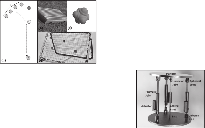
Figure 2: (a) Catching Practice (Hinchliffe, 2010), (b)
Katchet, (c) Reflex Ball and (d) Crazy Catch.
A traditional way of practicing slip catches is by
shooting a ball on a pitch roller. The ball hits the
curved surface of the roller and gets swerved towards
the fielder. Another realistic way to practice slip
catching requires a well-practiced coach to make it
worthwhile. As shown in Figure 2(a), the feeder (F)
throws the ball such that it reaches the coach (C) at
chest height, wide to the off side and the coach
deflects the ball with a bat into the slip cordon (S) for
practicing catches (Hinchliffe, 2010). A practice for
high catches can similarly be provided by an
experienced coach.
A Katchet, Reflex Ball and the Crazy Catch,
shown in Figure 2(b-d), are some presently used
devices that are used for practicing catches. These
methods deflect the ball in unpredictable directions
giving the fielder a good catching practice. But with
these devices, it is very difficult to send the ball in
desired directions, at desired angle or with desired
velocity to practice specific type of catches. Sending
the ball in desired manner is required to practice
specifically on players’ weak spots.
These existing methods are heavily dependent on
coach and do not provide any controlled training for
practicing catches. The work presented here proposes
the use of robotics technology to provide a controlled
and robust catching practice environment by using a
2-DOF Platform to provide a variety of catches in
desired locations.
3 DESIGN, GEOMETRY AND
INVERSE KINEMATIC
ANALYSIS OF THE PLATFORM
3.1 Design
There are two choices for the architecture of the 2-
DOF platform, a Serial Chain or a Parallel Chain
(Mecademic, 2013). Parallel chain platforms have
high payload capacity, are stiffer, faster, and more
accurate than serial ones, and is suitable for our
application. In our work, we have assumed that the
Ball Shooting Machine has a rotary degree of
freedom and is able to shoot the ball accurately on the
centre the platform. Hence, there is no requirement
for translational degrees of freedom for the platform
and the two rotational degrees of freedom i.e. roll and
pitch are sufficient to direct the ball in desired
directions.
Figure 3: A CAD model of the Redundantly Actuated 2-
DOF 3-UPS Parallel Platform.
An obvious choice is, therefore, a 2-DOF Parallel
Mechanism. Redundant actuation and novel
Cricket Catching Drills - Application of a Redundantly Actuated 2-DOF 3-UPS Parallel Platform to Increase the Efficacy of Providing
Catching Practice Drills in Cricket
191
redundant kinematics are discussed by Andreas
Muller (Müller 2008). Redundant actuation of the
platform increases the payload and acceleration, and
can yield an optimal load distribution among the
actuators. It also promises to improve platform
stiffness, dexterity and reliability. This led us to use
and explore the 2-DOF redundantly actuated 3-UPS
(Universal Joint – Prismatic Joint – Spherical Joint)
parallel mechanism (Figure 3) to manipulate the ball
for catching practice.
The design consists of a platform, a fixed base,
three identical limbs, and a central strut connected to
the platform with a universal joint, as in Figure 3. The
central strut is used to connect the platform to the
base. Each limb consists of a prismatic joint and is
attached to the platform with a spherical joint and to
the base with a universal joint. Due to the fact that
three actuators are used for operating this 2 DOF
platform, the mechanism is redundantly actuated.
3.2 Inverse Kinematics of the Platform
The Inverse Kinematical Analysis of a 2-DOF
Redundantly actuated 3-UPS Platform has been done
by Saglia et al., (2008).
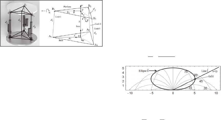
As shown in Figure 4, two Cartesian coordinate
systems
,,
as the fixed frame attached to the base
and
,,
moving reference frame attached to the
platform, are chosen, with
,,
and
,,
as the
unit vectors of the reference frames O and P,
respectively.
Figure 4: Geometry of the Parallel Mechanism and frame
assignment.
Defining two rotation angles and as roll and
pitch about axes and , we can describe the
orientation of the moving platform with respect to the
base frame.
Referring to Figure 4, a loop-closure equation for
each limb i in vector form can be written as
(1)
where
is the
limb vector, is the position vector
of moving frame origin in base frame,
,
, and
are the position vectors of the joint
expressed in
the base reference frame, the position of the
joint
expressed in the platform fixed orientation reference
frame, and the position of the
joints expressed in
the moving reference frame, respectively.
is the
rotation matrix representing the orientation of moving
frame in base frame. The vector of actuated joint
positions for three limbs is defined as
(2)
However, we are more interested in finding out the
unit vector normal to the platform after it undergoes
the rotation
. The vector is given by
(3)
Let
then,
2
,
(4)
2
,
/
(5)
4 ALGORITHM TO CALCULATE
THE VELOCITY AND ANGLE
OF LAUNCH FOR THE BALL
4.1 Terminology and Symbols
Following terminology and symbols are used in the
following development:
4.1.1 Ellipse of Points of Maximum Heights
(Ê)
As shown in Figure 5, the curve joining the points of
maximum height in the parabolas of ideal projectile
motion can be shown to be an ellipse (Fernández-
Chapou et al., 2004). We use this for formulating our
method and denote this ellipse by the symbol
Ȇ
.
The equation of ellipse Ȇ is given by
1
(6)
Figure 5: Ellipse of points of maximum heights (Fernández-
Chapou et al., 2004).
where,
,
, with
as the magnitude of
initial velocity of projectile and is the acceleration
icSPORTS 2015 - International Congress on Sport Sciences Research and Technology Support
192
due to gravity.
4.1.2 Locus of the Rightmost Points of the
Ellipse Ȇ (Line Ĺ)
The rightmost point of the ellipse Ȇ is
,
and as
2, we get the locus of the rightmost points of the
family of ellipses Ȇ as
2 which turns out to be a
line. We denote this line by the symbol ĺ.
4.1.3 Angle of Launch
)
The angle of launch for any point k lying on the
ellipse Ȇ can be found by the following equations:
1
2
sin
2
(7)
2
1
2
sin
2
(8)
where, x and y are coordinates of the point.
4.2 Computation of the Ball Velocity
and Angle of Launch for High
Catches
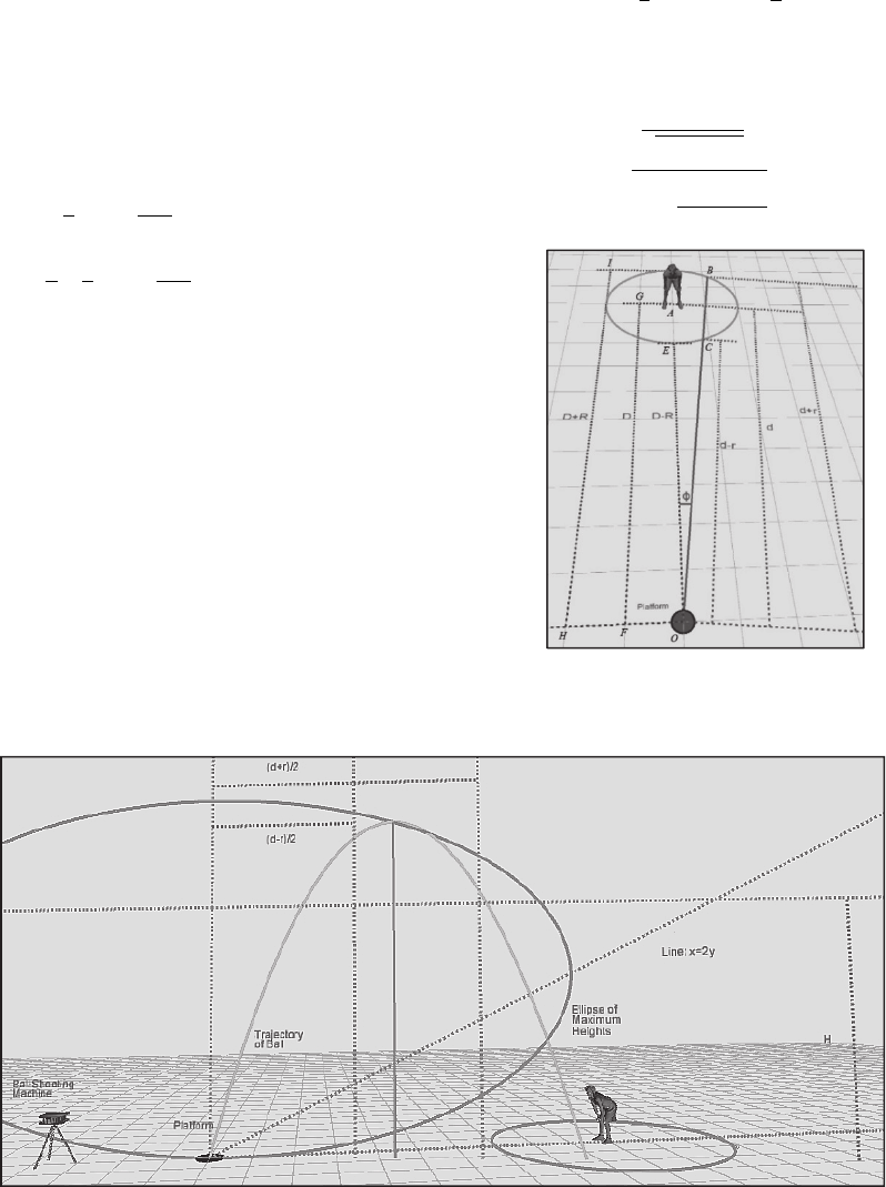
Every fielder has a maximum area of reach on the
field where he can get to and make a catch possible.
We define this area as a circle of radius R. A catch has
been defined as a high catch if the point of maximum
height of the ball’s trajectory is greater than or equal
to a user defined value H and falls in the area of
maximum reach i.e. a circle of radius R. Figure 6
shows an example of a High catch.
Our aim is to find an appropriate velocity and
angle of launch for the ball so that it lands in the area
of maximum reach of the fielder.
As shown in Figure 7, let the line OB formed by
the plane of the ball’s trajectory and the ground make
an angle of Φ with the line OA joining the centre of
the platform and the position of the player. The value
of Φ is restricted by the circle of maximum reach in
the range
sin
and sin
where, is the
distance of the fielder from the platform. The
distances and are given by the following
equations:
cot
√
1cot
(9)
1cot
(10)
Figure 7: The projected ball must fall anywhere on the
segment BC.
Figure 6: A High Catch Geometry.
Cricket Catching Drills - Application of a Redundantly Actuated 2-DOF 3-UPS Parallel Platform to Increase the Efficacy of Providing
Catching Practice Drills in Cricket
193
The solution is developed by restricting the
horizontal range of the ball between and
(i.e. segment BC) such that the maximum height
attained by the ball is greater than or equal to H. A
projectile attains maximum height when it has
covered half of its horizontal range. Therefore, the x
coordinate of the point of maximum height for the
projected ball must lie between the values
/2
and /2. Figure 8 shows an ellipse Ȇ
drawn for a certain velocity. The segment AB of the
ellipse Ȇ shown in this figure, thus contains the
suitable points of maximum height of the trajectory
of projected ball.
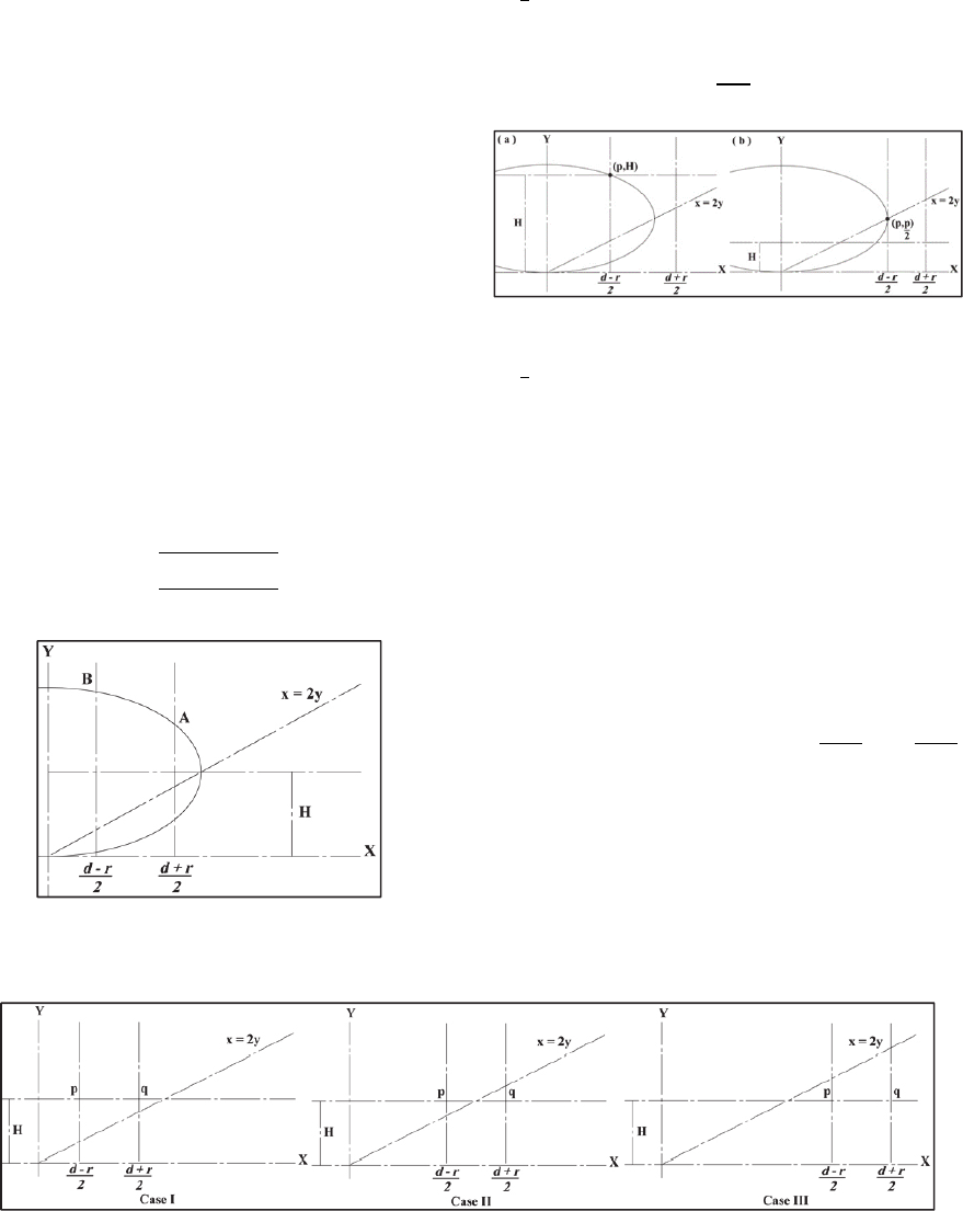
Three situations are possible for the catch as
shown in Figure 9. Case I has both the points p and q
on the left hand side of the line ĺ, Case II has the line
ĺ lying between the points p and q and Case III has the
points p and q on the right hand side of line ĺ. Each
case will have an Ellipse Ê corresponding to the
minimum velocity
that satisfies the condition for
the range of the ball to lie between
and
and attain maximum height greater than or equal to
H. For Case I, this ellipse should pass through the
point
, as shown in Figure 10(a). Substituting
this point in the ellipse equation (6) gives us the
expression for
as:
4
4
8
(11)
Figure 8: The segment AB of the ellipse contains the
suitable points of maximum heights.
The ellipse Ê corresponding to the minimum
velocity for Case II also passes through the point
, and the velocity is again given by the equation
(11). For Case III, this ellipse passes through the point
,
sitting on the line ĺ as shown in Figure 10(b).
Substituting this point in equation (6) gives the
following expression for
2
(12)
Figure 10: Ellipse corresponding to the velocity
(a)
passing through (p,H) for Case I and (b) passing through
,
for Case III.
The maximum velocity
of the ball is
restricted by the Ball Shooting Machine. We choose
a random velocity
between
and
, draw
the ellipse Ȇ corresponding to this chosen velocity,
find suitable segments of this ellipse (as was done in
Figure 8) and hence calculate the range of values for
the angle of launch which satisfy the conditions
required.
Depending on the distances d, r, H and the chosen
velocity
, two subcases for Case I, three subcases
for Case II and five subcases for Case III arise which
are shown in Figure 11. The segments on each of the
ellipse constrained by the region
,
and
, contain the suitable points of maximum
height. A range of values for the angle of launch is
calculated for each case and a random angle
is
selected from this range.
Figure 9: Three Cases for a High Catch.
icSPORTS 2015 - International Congress on Sport Sciences Research and Technology Support
194
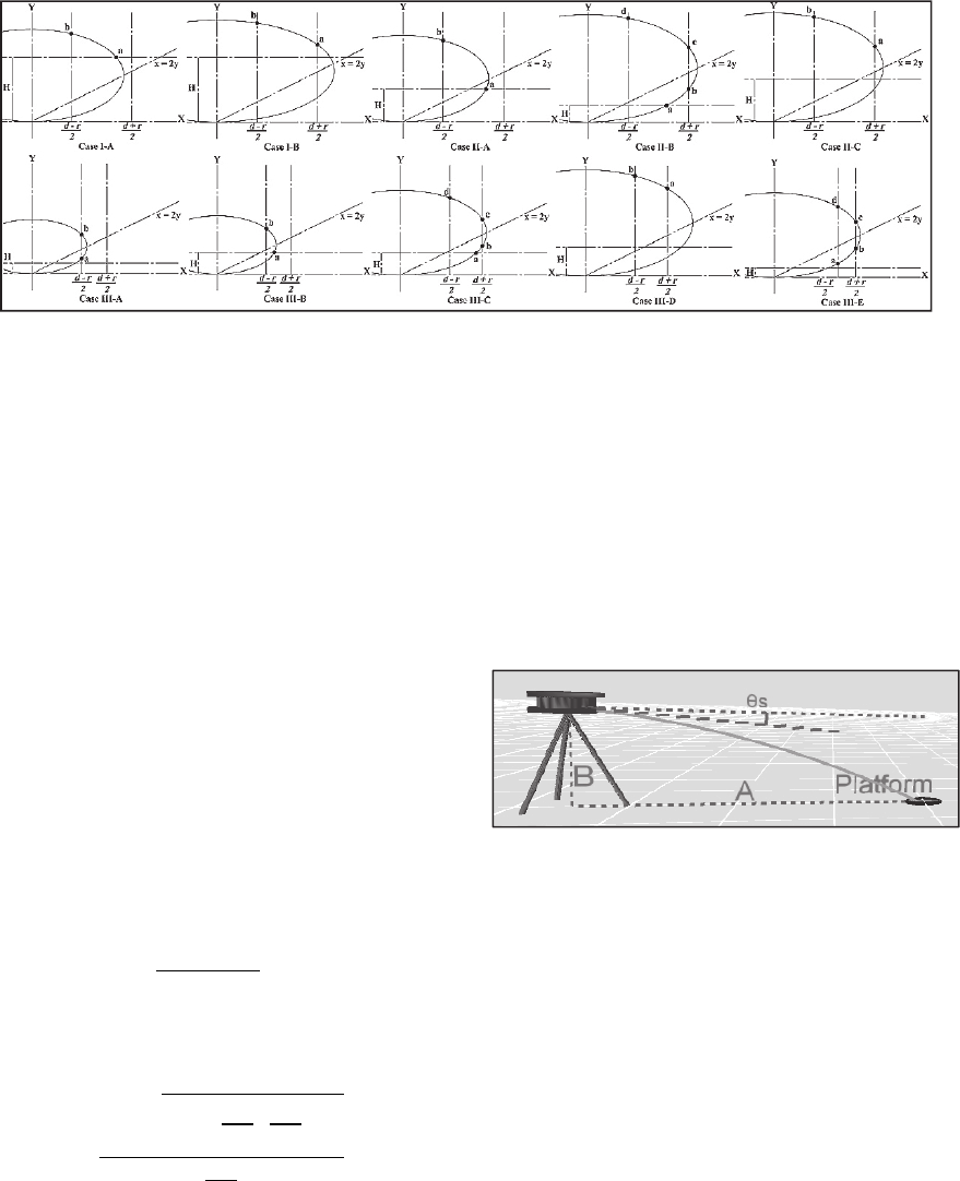
Figure 11: Subcases for Case I, Case II and Case III of High Catches.
For example, for Case III-C in Figure 11,
,
(13)
,
(14)
,
(15)
where, the function
, returns a random
value between the values and .
5 VELOCITY AND ANGLE OF
LAUNCH OF THE BALL SHOT
FROM BALL SHOOTING
MACHINE
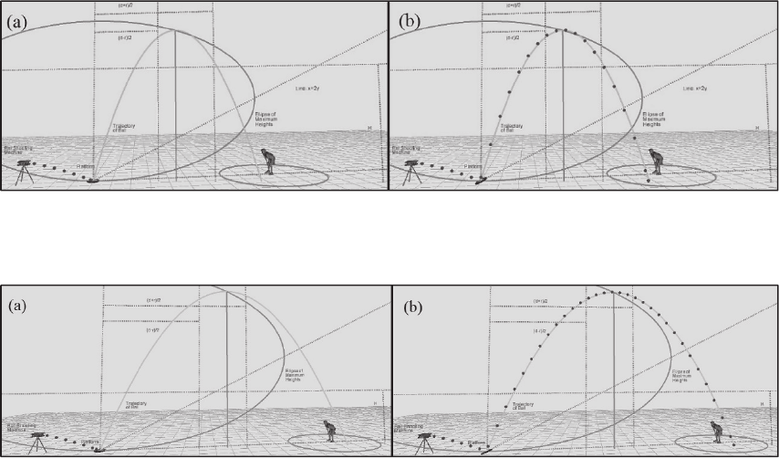
As shown in Figure 12, let the Ball Shooting Machine
be placed at a distance A from the platform and the
ball be shot from a height of B from the ground. If
is the required velocity of launch as the ball leaves the
platform after hitting it, then the velocity of launch
from the Ball Shooting Machine is given by the
expression
2
(16)
The angle of launch
can be found from the
expression
tan
2
2
(17)
6 ORIENTATION OF PLATFORM
The orientation of the platform to swerve the ball shot
from the ball shooting machine is computed as
follows. If
be the velocity vector of the ball just
before striking the platform and
the velocity
vector just after striking the platform, then the unit
vector normal to the platforrm is given by
(18)
where, norm provides a normalized vector. Equations
(2)-(5) along with equation (18) can be used to
calculate vector of actuated joint positions of three
limbs supporting the platform.
Figure 12: Trajectory of the ball shot from the Ball Shooting
Machine onto the platform.
7 SIMULATION AND RESULTS
The simulation of the proposed system was done in
an Open-Source Software, Processing
(Processing.org, 2001). The simulation results for
High Catches launched at various speeds and launch
angles are shown in the Figures 13-15. For all the
simulations, the maximum velocity of launch for the
ball that can be provided is constrained by the Ball
Shooting machine and is taken as 30 m/s. Figure 13
shows an example of the Case I-B for a High Catch.
In this example, the parameters D, R, Φ and H have
the values 10 m, 3 m, 0.2 rad and 6 m respectively.
The minimum velocity of launch for this case can be
found using the equation 11. This provides a range
from 11.36 m/s to 30 m/s for choosing the velocity of
Cricket Catching Drills - Application of a Redundantly Actuated 2-DOF 3-UPS Parallel Platform to Increase the Efficacy of Providing
Catching Practice Drills in Cricket
195
launch for the ball. In this example, the velocity of
launch was chosen as 13.00 m/s. This chosen velocity
in turn provides a range from 1.184 rad to 1.344 rad
for the angle of launch. In this example, the angle of
launch was chosen as 1.30 rad. Figures 14 and 15 are
the examples of Case II-C and Case III-D
respectively. The velocity and the angle of launch for
the ball are calculated using similar steps as used for
the example in Figure 13.
These simulation results prove the idea that the
proposed 2-DOF 3-UPS Parallel Platform can be very
effectively used for catching practice drills in Cricket
and can be used to train the players for their weak
points. The platform is being fabricated to perform
field trials.
8 CONCLUSIONS AND FURTHER
WORK
Employing a 2-DOF platform creates catching drills
maintaining a degree of realism. Our formulated
method of simulating catches can be used to devise
one’s own set of catching drills.
This work focused on the formulation of a
methodology to provide training for High Catches.
With the success for High Catches training, the work
is continuing with the formulation of models for other
types of catches like Slip Catches and Flighted
Catches and their verification by simulation.
This work does not consider the effect of air drag,
wind velocity and other effects which deviate a
projectile from its actual parabolic trajectory. In
realistic situation, the ball shot from the Ball Shooting
Machine may not hit the center of the platform due to
these unconsidered effects. This problem will require
the use of a 5-DOF (3 translational and 2 rotational)
platform.
It is difficult to predict the trajectory of the ball
considering changing environmental conditions
leading to the varying air drag, wind velocity and
other effects. This can be tackled by making use of
Visual Servoing to control the 5-DOF platform in
real-time, which in-fact is also a long term goal of this
work.
Regrettably, our platform is incapable of
simulating aspects, related to body
position/movement of the batsman and we also aim to
tackle this endeavour in our future work.
Figure 13: Screenshots of Simulation of a High Catch with Launch velocity of 13.00 m/s, angle of launch = 1.30 rad, H =
6 m, D = 10 m, R = 3 m and Φ = 0.2 rad. (a) Trajectory of the ball as shot from the Ball Shooting Machine towards the
platform. (b) Swerved trajectory of the ball after actuation of the platform.
Figure 14: Screenshots of Simulation of a High Catch with Launch velocity of 15.00 m/s, angle of launch = 1.19 rad, H =
3.5 m, D = 15 m, R = 3 m and Φ = 0.079 rad. (a) Trajectory of the ball as shot from the Ball Shooting Machine towards the
platform. (b) Swerved trajectory of the ball after actuation of the platform.
icSPORTS 2015 - International Congress on Sport Sciences Research and Technology Support
196
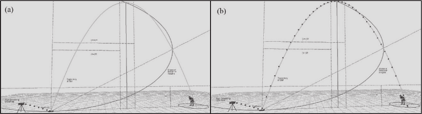
Figure 15: Screenshots of Simulation of a High Catch with Launch velocity of 18.00 m/s, angle of launch = 1.25 rad, H =
3 m, D = 20 m, R = 2 m and Φ = 0.059 rad. (a) Trajectory of the ball as shot from the Ball Shooting Machine towards the
platform. (b) Swerved trajectory of the ball after actuation of the platform.
ACKNOWLEDGEMENTS
Authors express their gratitude to Mohammad Shakir,
Mohit Padhy and Shaleen Manocha of BITS Pilani
Cricket Team, for their valuable suggestions and
support.
REFERENCES
Fernández-Chapou, J. L., Salas-Brito, a. L. & Vargas, C. a.,
2004. An elliptic property of parabolic trajectories.
Cornell University Library, p.4. Available at:
http://arxiv.org/abs/physics/0402020.
Hinchliffe, D., 2010. Fielding Drills: Slip catching nicks,
Cricket coaching, fitness and tips. Available at:
http://www.pitchvision.com/fielding-drills-slip-
catching-nicks.
Mecademic, 2013. What is a parallel robot? Available at:
http://www.mecademic.com/What-is-a-parallel-
robot.html.
Morgan, E., 2014. Eoin Morgan Unbelievable Shot in the
Big Bash! - YouTube. Available at:
https://www.youtube.com/watch?v=IC_lbWUZlsA.
Müller, A., 2008. Parallel Manipulators - Towards New
Applications H. Wu, ed., I-Tech Education and
Publishing.
Processing.org, 2001. Processing.org. Available at:
https://processing.org/.
Saglia, J. A., Dai, J. S. & Caldwell, D. G., 2008. Geometry
and Kinematic Analysis of a Redundantly Actuated
Parallel Mechanism That Eliminates Singularities and
Improves Dexterity. Journal of Mechanical Design,
130(12), pp.124501–1–124501–2.
Cricket Catching Drills - Application of a Redundantly Actuated 2-DOF 3-UPS Parallel Platform to Increase the Efficacy of Providing
Catching Practice Drills in Cricket
197
