An Instrumented Glove for Swimming Performance Monitoring
M. Mangin
1
, A. Valade
2
, A. Costes
3
, A. Bouillod
2,4
, P. Acco
2
and G. Soto-Romero
1,2
1
ISIFC - Génie Biomédical, 23 Rue Alain Savary, Besançon, France
2
LAAS-CNRS, N2IS, Toulouse, France
3
Université de Toulouse, UPS, PRISSMH, Toulouse, France
4
EA4660, C3S - Université de Franche-Comté, Besançon, France
Keywords: Glove, Performance Monitoring, Embedeed Electronics, Swimming, Wearable Device.
Abstract: This paper presents a project of wearable motion capture system for motion analysis in swimming. Two
versions of this system have already been designed, one with a wired structure, based on a microcontroller
and an inertial measurement unit (IMU), and the other with a distributed architecture, based on a wireless
communication and another IMU. This system has been initially designed to target tri-athletes population,
but this study only presents the considerations concerning the swimming application.
1 INTRODUCTION
Movement efficiency is a challenge in the training of
swimmers in order to increase their performances
(Callaway, 2015; Psycharakis and Sanders, 2010;
Ohgi et al., 1998). A coach can easily measure
stroke frequencies or split times but currently, it is
difficult to evaluate the swimming technique.
Indeed, underwater, 2D or 3D cameras (Samson et
al., 2012) have been traditionally used in order to
collect swimming kinematics, but they are
cumbersome and expensive, and they require an
heavy post-processing and a correct brightness.
This study presents a part of a project which
consists on developing a smart electronic measuring
system, supposed to be wearable and composed of
multi-sensors areas communicating with a central
station and a computer. The main application is the
quantification of swimming kinematics. In order to
improve its wearability, we have chosen to integrate
it into a glove which can be used by the swimmers.
The purpose of this study was to validate
different parts of the future system (accuracy of the
system, waterproofness, wireless communication)
and to collect preliminary hand kinematics from
both elite and recreational swimmers.
2 ARCHITECTURE DESIGN
2.1 Wired Approach
Our first approach was based on a previous study
(Hernandez et al., 2014) which presented an
instrumented glove used for the capture of hand
gestures for a surgical application. We propose
another application in sports by firstly developing a
wired system monitoring the hand positions of a
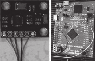
swimmer. We used an inertial measurement unit
(IMU MPU9150, InvenSense), which uses Inter-
Integrated Circuit (I2C) communication standard.
The MPU9150 includes a 3-axis gyroscope with a
full-scale range of ±250, ±500, ±1000, and ±2000
°/sec, a 3-axis accelerometer with a full-scale range
of ±2, ±4, ±8, and ±16 g, and a 3-axis magnetometer
with a full scale range of ±1200 µT. The gyroscope
and the accelerometer are in 16-bit resolution, and
the magnetometer is in 13-bit resolution.
Figure 1: MPU9150 (left) and TIVA launchpad (right).
Mangin, M., Valade, A., Costes, A., Bouillod, A., Acco, P. and Soto-Romero, G..
An Instrumented Glove for Swimming Performance Monitoring.
In Proceedings of the 3rd International Congress on Sport Sciences Research and Technology Support (icSPORTS 2015), pages 53-58
ISBN: 978-989-758-159-5
Copyright
c
2015 by SCITEPRESS – Science and Technology Publications, Lda. All rights reserved
53
This IMU was connected via wires to a
microcontroller on a Tiva C Series EK-
TM4C123GXL launchpad (Figure 1) which sent the
data at 50Hz. The microcontroller was programmed
to handle the data processing, which means reading
the raw data from the IMU, computing the sensor
orientation and sending the results to the computer
via USB data link.
2.2 Distributed Approach
Our second approach was to propose a distributed
processing (called AREM Gateway, or Gateway)
(Figure 2), where a sensor is connected to a
microcontroller (with embedded computing
algorithms) and equipped with a battery and a
wireless communication module. We made our
study with only one sensor, but our aim was to use
additional sensors. Thanks to this wireless
architecture, the Gateway would give two feedback
possibilities:
- a feedback at the end of a series of laps, with a
data post-processing,
- a direct feedback, as the data can be processed in
real-time by an algorithm embedded into the
microcontroller.
We used another IMU, a ST iNemo-M1, which
includes a 6-axis IMU (consisting on a 3-axis
accelerometer and a 3-axis magnetometer), a 3-axis
gyroscope and an ARM STM32 microcontroller. The
wireless transmission of the processed data is done
using an ESP8266 WiFi module working in a station
mode and connecting to a standard WiFi Access-
Point. We also added a USB connector for the
microcontroller, in order to communicate with a
computer and to charge the battery, and a Serial-
ATA connector connected to a Serial Peripheral
Interface (SPI) bus to enable extension capabilities
(with a SD card for example). Finally, the Gateway
is 31 mm wide, 44 mm long, 13 mm high (with the
battery and connectors), and weights 15 g with a 300
mAh battery, which has been tested and supply
power for 2h30 in normal operation mode.
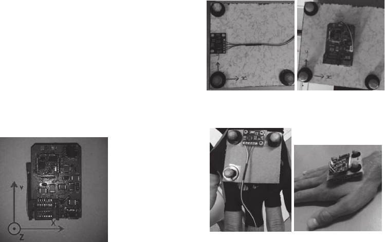
Figure 2: Second version of the system (Gateway).
3 VALIDATION
3.1 Laboratory Tests
During the development of our systems, our first aim
was to validate the hand swimming kinematics
thanks to the IMU. In view of this, we compared
pitch, roll and yaw angles provided both by the IMU
of the wired system and the Gateway and a Vicon
system (using Nexus 1.7.1 software), a marker-based
motion capture system acknowledged as a reference.
This motion capture system carries 12 MX3+
cameras with a frequency of 200 Hz, a millimeter
accuracy and a resolution of 659 × 494 pixels each.
We set up two trials in order to compare the IMU
with the Vicon system. Each trial was filmed and
recorded with both systems (wired and distributed).
For the first, the IMU was surrounded with three
reflective passive markers (Figure 3) and controlled
by software (sample code from Texas Instruments,
and TeraTerm for the TIVA and a Python script for
the Gateway as computer softwares). We put it on a
table at the center of a room equipped with the
Vicon system, and we collected data with the IMU
and the Vicon system simultaneously during a
rotation about a spatial axis. We made these
rotations successively around the three axes in order
to obtain the roll, pitch and yaw movements. For the
second trial, we put the IMU on the hand of a
swimmer (Figure 4) and we asked him to simulate a
crawl movement while collecting data with both the
IMU and the Vicon system.
Figure 3: Settings for the first experiment (left: wired,
right: distributed).
Figure 4: Settings for the second experiment (left: wired,
right: distributed).
icSPORTS 2015 - International Congress on Sport Sciences Research and Technology Support
54
To compare the data collected with the IMU and
the Vicon system, we first had to convert the
coordinates provided by the Vicon cameras into
angles. To do so, we used an algorithm with a
simple angular projection leading to a coherent
result for simple rotations around X, Y or Z axis.
Finally, we were able to compare the data collected
by both systems (Figure 5).
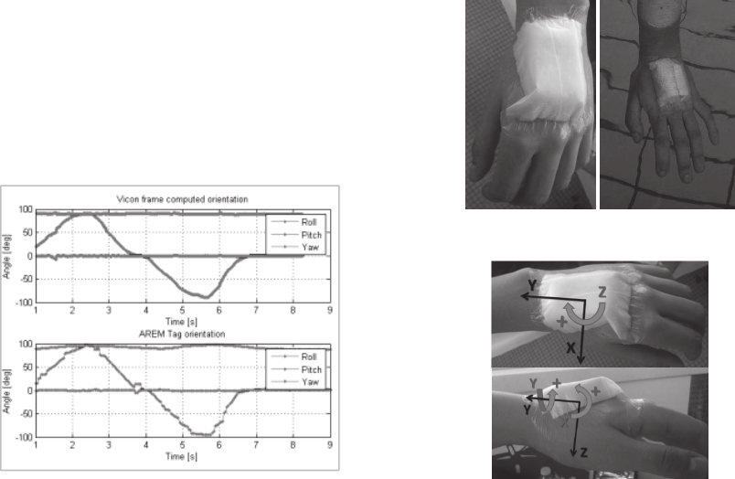
Figure 5: Comparison between IMU and Vicon for the
roll, pitch and yaw angles (defined with respect to the
sensor’s orientation).
Moreover, we are currently working on an
algorithm based on the method described by Arun,
Huang and Blostein (Arun, Huang and Blostein,
1987), to determine rotation matrixes and translation
vectors with Vicon coordinates as inputs to deduce
Euler’s angles. Knowing the rotation matrix, we will
be able to determine the sensor’s attitude. This will
allow us to compare two methods of conversion, and
to determine which one is the most accurate.
3.2 Preliminary Field Tests
After the lab tests, we wanted to carry out field
validation tests. Ensuring waterproofness appeared
more difficult with the wired version, because we
hadn’t any glove prototype available yet.
Consequently, we decided to do the trials in pool
only with the Gateway.
Firstly, we tested the WiFi communication
provided by the ESP8266 WiFi module (2,4 GHz) in
a swimming pool in order to establish if the
communication was possible in such an environment
(water surrounding, metallic structure), and if it was
possible under water. To do so, we attached the
Gateway to the hand of a swimmer and we asked her
to put gradually her hand in the water until the loss
of the communication (Figure 6). The orientation of
the IMU is presented in Figure 7.
Figure 6: First tests of the WiFi communication.
Figure 7: IMU’s orientation during the field preliminary
tests.
We noted that the depth limit was about one
centimeter (under this depth, the WiFi signal was
lost), but that the communication was very good on
the surface of the water despite the environment
quite unfavorable to the correct travel of
electromagnetic waves.
Secondly, we decided to test the range of the
WiFi signal next to and in the swimming pool. We
noticed that the distance between the Gateway and
the surface of the water didn’t change the range of
the signal, and we determined it at about sixty
meters.
Thirdly, we tested data recording with the
Gateway during a fifty meters swim by two
swimmers. Because of the impossibility to
communicate underwater, we chose to record the
data when the WiFi signal was lost and to send them
at the end of each lap (at the communication
restoration). We managed to retrieve the data
corresponding to five crawl movements of each
swimmer.
4 RESULTS AND DISCUSSION
As the present study is a work in progress, the
following part will present results based on
preliminary field tests, introduce test protocols and
Yaw
Roll
Pitch
An Instrumented Glove for Swimming Performance Monitoring
55
analyses we want to realize with athletes, before
talking about the design we have proposed for the
glove.
4.1 WiFi Communication Tests
We draw out two options from this experiment: 1)
we had to change the frequency of the wireless
signal (in order to limit the absorption of the signal
by the water) or 2) to reconsider the wireless
communication strategy. In fact, we would have to
adapt our system to record the data and transmit
them to a computer when the Gateway is out of the
water (at the end of a swim lap). This improvement
would enable us to propose a real-time feedback, or
at least a faster feedback.
4.2 Swimming Evaluation
In order to get preliminary data related to the hand
movement of a swimmer, we will work in
collaboration with recreational and elite athletes.
We supposed that elite swimmers would have a
hand trajectory which permit them to be more
effective, that’s why it could be interesting to
compare hand kinematics of both groups in order to
assess differences between elite and recreational
swimmers.
Athletes will be asked to do a self-determined
warm-up before being equipped with the Gateway
on the left hand. Then they will have to perform
crawl during fifty meters, without a diving start, in a
fifty meters swimming pool. In order to standardize
the measurements, the swimmers will be asked to
put their hand at the surface of the water, in the
direction of the pool, before beginning to swim.
Data will be recorded in an external memory (SD
card) and collected on a computer at the end of each
lap.
4.3 Parameters Extraction
From the variations of pitch, roll and yaw angles
provided by the Gateway, the challenge was to
interpret the collected data. First, it is necessary to
correlate the curves obtained with hand positions,
and then to determine what is the most effective
trajectory. Moreover, it would be interesting to
evaluate if the hand acceleration (Hagema et al.,
2013) could be associated with swimming
effectiveness.
Our approach is the following: we are comparing
hand angles between different swimmers in order to
distinguish both elite and recreational swimmers.
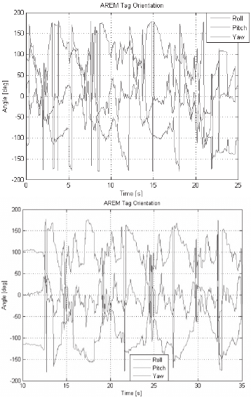
Preliminary data comparing a recreational and an
elite swimmers are presented in Figure 8.
With the current state of the study, we can make
the following preliminary interpretations. A decrease
of the roll angle can be interpreted as the beginning
of the crawl movement, when the swimmer draws
water. In this part of the movement, the yaw angle
represents the hand’s direction. Indeed, if it
decreases, the hand is pulling from the left to the
right, and if it increases, the hand is pulling from the
right to the left. Afterwards, an increase of the roll
and yaw angles can correspond to a hand’s lateral
displacement, which is an example of a movement to
avoid.
A perspective of analysis is a comparison of two
crawl movements: a “correct” movement and a
movement where the arms are stretched (Figure 9).
Figure 8: Comparison between a recreational (top) and an
elite (bottom) swimmers.
Because of dealing with raw data in these
figures, we can emphasize the need of a fast filtering
algorithm to correct some unattended points like
“gimbal lock” and also compute useful data for real
time retrieval. Some recent works (Janota et al.,
2015) explain how to perform the Euler angles
computing, and we expect to include that correction
on IMU chips.
icSPORTS 2015 - International Congress on Sport Sciences Research and Technology Support
56
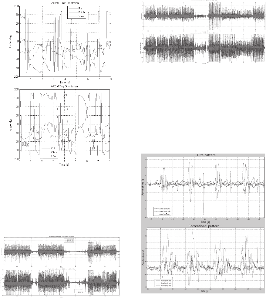
Figure 9: Two different crawl movements (top: incorrect,
bottom: correct).
However, our system also measures the 3-axis
accelerations, angular velocities (and magnetic field
which will not be detailed in this paper). A first
comparison between elite and recreational swimmers
showed a difference in acceleration amplitude on
different styles (Figures 10 and 11).
Figure 10: Acceleration (top, in g) and angular velocities
(bottom, in deg.s
-1
) during an elite swimmer test: 2x200m
frontcrawl and 200m Medley (red: X, green: Y and blue: Z
axis).
A more fine analysis showed differences on
patterns and amplitudes/frequencies for each style.
That suggests the interest of establishing a “quality
factor” qualifying the swim, based on pattern
analysis, to evaluate swimmer stroke and give a real
time feedback.
Figure 11: Acceleration (top, in g) and angular velocities
(bottom, in deg.s
-1
) during a recreational swimmer test:
200m frontcrawl and 200m Medley (red: X, green: Y and
blue: Z axis).
We show on next figure (Figure 12) the front
crawl pattern, being the most analyzed (Dadashi,
Crettenand and Millet, 2012). But that pattern will
be studied for other swimming styles, like
backstroke. We expect to be able to perform the
analysis of fatigue impact on swimmer stroke, by
storing data from long distance tests.
Figure 12: Comparison between elite (top) and
recreational (bottom) front crawl stroke pattern.
4.4 Glove Design
In parallel of the development of the electronic part,
we proposed different kinds of shapes for the glove.
For the prototype, we decided to develop a glove
without fabric on the palm and the fingertips. The
lengths of fabric on the fingers have been chosen in
order to permit the addition of pressure sensors
(Figure 13).
An Instrumented Glove for Swimming Performance Monitoring
57
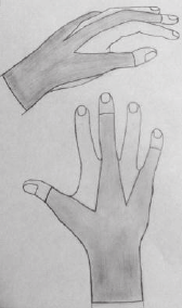
Figure 13: Drawings of the first design of the glove.
The glove has been proposed to two swimmers to
collect their perceptions and their opinions. They
appreciated the fact that the palm and the fingers tips
were free, and didn’t feel disturbed by the glove. But
they underlined the need to adjust correctly the size
in order to prevent the passage of water at the back
of the hand, and the slight difficulty of putting the
glove on.
5 CONCLUSIONS
The preliminary interpretation seems to show that
the Euler’s angles variation would be a first
interesting parameter to quantify the swimming
technique. Indeed, the correlation between the
curves and the movements would enable to provide
to the swimmer certain necessary adjustments
without a video recording or the observation of his
coach. But the understanding of the curves obtained
implies a correction of the data collected, because
the curves seem to contain some aberrant points.
A more common analysis, according to literature,
shows a difference in patterns between elite and
recreational swimmers. More than recognizing the
swimming style, the next step will be to extract a
quality stroke index by style and perform fatigue
analysis on swimmers.
This study represents a step forward in the
development of a wearable motion capture system to
monitor swimming performances. It also underlines
the fact that the wireless communication must be re-
engineered in order to transmit data underwater.
In a further study, we would like to add several
pressure sensors in order to provide information
relative to the force exerted by the athlete on the
water. This would be another parameter to assess
swimming kinetics, in addition to the kinematics
provided by the sensors presented in this study.
ACKNOWLEDGEMENTS
This research project is partially supported by TE
Connectivity and Compressport International. The
authors would like to thank Mrs. Marie Percebois,
Mr. Manuel Roux, Mr. Louis Cupillard, and others
coaches and athletes from Besançon Triathlon and
Toulouse Université Club (TUC Triathlon), for their
assistance in swimming tests.
The authors would also like to gratefully
acknowledge Mrs. Kris Martinez, Mr. Xavi Carabi
and Mr. Sylvain Laur, from Compressport Int, for
their help in glove design and first prototypes of
wearable devices.
REFERENCES
Callaway, A. J. Measuring Kinematic Variables in Front
Crawl Swimming Using Accelerometers: A Validation
Study. Sensors 2015, 15, 11363-11386.
Psycharakis, S. G.; Sanders, R. H. Body roll in swimming:
A review. J. Sports Sci. 2010, 28, 229–236.
Ohgi, Y.; Ichikawa, H.; Miyaji, C. Characteristics of the
forearm acceleration in swimming. Proceedings of the
Symposium on Biomechanics and Medicine in
Swimming VIII, Jyväskylä, Finland, 28 June–2 July
1998; Kesikinen, K.L., Komi, P.V., Hollander, A.P.,
Eds.; pp. 77–82.
Samson, M.; Bernard, A.; David, L. Mesures cinématiques
et dynamiques en fin de phase d’allongement du
crawl. 13
ème
Congrès Francophone de Techniques
Laser 2012.
Hernandez, A. M.; Lemos, J. D.; Soto-Romero, G.;
Valade, A. Instrumented glove for skills assessment in
neurosurgical simulation. Biomedical Circuits and
Systems Conference (BioCAS), 2014.
Arun, K. S.; Huang, T. S.; Blostein, S. D. Least-squares
fitting of two 3-D point sets. IEEE Transactions on
Pattern Analysis and Machine Intelligence, 9, 5, 1987,
pp. 698-700.
Hagema, R. M; Haelsig, T.; O’Keefe, S. G; et al. Second
generation swimming feedback device using a
wearable data processing system based on underwater
visible light communication. Procedia Engineering
60, 2013, pp. 34-39.
Aleš Janota; Vojtech Šimák; Dušan Nemec and Jozef
Hrbček. Improving the Precision and Speed of Euler
Angles Computation from Low-Cost Rotation Sensor
Data. Sensors 2015, 15, 7016-7039.
Farzin Dadashi; Florent Crettenand; Grégoire P. Millet
and Kamiar Aminian. Front-Crawl. Instantaneous
Velocity Estimation Using a Wearable Inertial
Measurement Unit. Sensors 2012, 12, 12927-12939.
icSPORTS 2015 - International Congress on Sport Sciences Research and Technology Support
58
