Time Evolving Expert Systems Design and Implementation: The
KAFKA Approach
Fabio Sartori and Riccardo Melen
Department of Computer Science, Systems and Communication, University of Milano-Bicocca, viale Sarca 336, Milan, Italy
Keywords:
Knowledge Artifact, Knowledge Acquisition, Android OS.
Abstract:
Expert Systems design and implementation has been always conceived as a centralized activity, character-
ized by the relationship between users, domain experts and knowledge engineers. The growing diffusion of
sophisticated PDAs and mobile operating systems opens up to new and dynamic application environments
and requires to rethink this statement. New frameworks for expert systems design, in particular rule–based
systems, should be developed to allow users and domain experts to interact directly, minimizing the role of
knowledge engineer and promoting the real–time updating of knowledge bases when needed. This paper
present the KAFKA approach to this challenge, based on the implementation of the Knowledge Artifact con-
ceptual model supported by Android OS devices.
1 INTRODUCTION
Traditional knowledge engineering methodologies,
like CommonKads (Schreiber et al., 1994) and
MIKE (Angele et al., 1998), considered knowledge
acquisition and representation as centralized activi-
ties, in which the main point was trying to build up
facts’ and rules’ bases where to model tacit knowl-
edge in order to use and maintain it. Indeed, the ex-
plosion of Internet and related technologies, like Se-
mantic Web, Ontologies, Linked Data ... has radically
changed the point of view on knowledge engineering
(and knowledge acquisition in particular), highlight-
ing its intrinsically distributed nature.
Finally, the growing diffusion of more and more
sophisticated PDAs, like smartphones and tablets,
equipped with higher and higher performing hard-
ware and operating systems allows the distributed im-
plementation on mobile devices of several key com-
ponents of the knowledge engineering process. A di-
rect consequence of these considerations is the need
for knowledge acquisition and representation frame-
works that are able to quickly and effectively under-
stand when knowledge should be integrated, minimiz-
ing the role of knowledge engineers and allowing the
domain experts to manage knowledge bases in a sim-
pler way.
A relevant work in this field has been recently
proposed in (Nalepa and Lig˛eza, 2010): the HeKatE
methodology aims at the development of complex
rule–based systems focusing on groups of similar
rules rather than on single rules. Doing so, efficient
inference is assured, since only the rules necessary
to reach the goal are fired. Indeed, this characteris-
tic helps the user in understanding how the system
works, as well as how to extend it in case of need,
minimizing the knowledge engineer role. Anyway,
our goal is (partially) different, to build a tool for sup-
porting the user in understanding when the knowledge
base should be updated, according to the domain con-
ditions he/she detects on the field. For this reason, we
don’t aim to build up new inference engines, like in
the HeKatE project, but a good framework to use ex-
isting tools usable in varying conditions and portable
devices.
In this paper, we present KAFKA (Knowledge Ac-
quisition Framework based on Knowledge Artifacts),
a knowledge engineering framework developed un-
der Android: the most interesting feature of KAFKA
is the possibility for the user to design and imple-
ment his/her own knowledge–based system without
the need for a knowledge engineer. The framework
exploits Android as the running OS, since it is the
most diffused mobile operating system in the world:
the final aim of KAFKA is the execution of expert
systems written in Jess. Due to the difficulties in im-
porting Jess under Android, KAFKA has been cur-
rently developed as a client–server architecture. The
most important characteristic of Jess, from KAFKA
point of view, is the possibility to implement facts as
84
Sartori, F. and Melen, R..
Time Evolving Expert Systems Design and Implementation: The KAFKA Approach.
In Proceedings of the 7th International Joint Conference on Knowledge Discovery, Knowledge Engineering and Knowledge Management (IC3K 2015) - Volume 2: KEOD, pages 84-95
ISBN: 978-989-758-158-8
Copyright
c
2015 by SCITEPRESS – Science and Technology Publications, Lda. All rights reserved
Java objects rather than simple (attribute, value) pairs
exploiting the shadow fact construct. This point, to-
gether with the conceptual model of Knowledge Ar-
tifact adopted in designing the expert system makes
possible to understand when new rules and observa-
tions should be modeled according to the evolution of
the underlying domain.
The rest of the paper is organized as follows: sec-
tion 2 briefly introduces the research field, focusing
on distributed expert systems and Knowledge Arti-
facts. Section 3 further explores the Knowledge Ar-
tifact concept from the perspective of time evolving
expert systems. Section 4 presents the characteristics
of problems and domains addressed by KAFKA: in
particular, the role of Knowledge Artifact and rules is
analysed from both the conceptual and computational
point of view, in order to explain how KAFKA al-
lows the user to take care of possible evolutions of the
related expert system. In section 5 a case study is pre-
sented, illustrating how KAFKA allows the user to in-
teract with the domain expert to complete knowledge
bases when new observations are available. Finally,
conclusion and further work end the paper.
2 RELATED WORK
As reported in (Schreiber, 2013), with the advent of
the web and of Linked Data, knowledge sources pro-
duced by experts as (taxonomical) description of do-
mains’ concepts have become strategic assets: SKOS
(Simple Knowledge Organizations System) has been
recently released as a standard to publish such de-
scription in the form of vocabularies.
In this way, knowledge engineering has moved
from being a typical centralized activity to being dis-
tributed: many experts can share their competencies,
contributing to the global growth of knowledge in a
given domain. The expert system paradigm has be-
come suitable to solve complex problems exploiting
the integration between different knowledge sources
in various domains, as medicine (Yan et al., 2004)
and chemistry (Bonastre et al., 2001), and innovative
frameworks have been developed to allow non AI ex-
perts to implement their own expert systems (Ruiz-
Mezcua et al., 2011; Rybina and Deineko, 2011).
In this paper, we propose an alternative approach
to the development of distributed expert systems,
based on the Knowledge Artifact (KA) notion. In
Computer Science, artifacts have been widely used in
many fields; Distributed Cognition (Norman, 1991)
described cognitive artifacts as “[...] artificial de-
vices that maintain, display, or operate upon infor-
mation, in order to serve a representational function
and that affect human cognitive performance”. Thus,
artifacts are able not only to amplify human cognitive
abilities, but also change the nature of the task they
are involved into. In CSCW, coordinative artifacts
(Schmidt and Simone, 2000) are exploited “[...] to
specify the properties of the results of individual con-
tributions [...], interdependencies of tasks or objects
in a cooperative works setting [...] a protocol of inter-
action in view of task interdependencies in a cooper-
ative work setting [...]”, acting as templates, maps or
scripts respectively. In the MAS paradigm (Omicini
et al., 2008), artifacts “[...] represent passive compo-
nents of the systems [...] that are intentionally con-
structed, shared, manipulated and used by agents to
support their activities [...]”.
According to the last definition, it is possible to
highlight how artifacts are typically considered pas-
sive entities in literature: they can support or influ-
ence human and artificial agents reasoning, but they
are not part of it, i.e. they don’t specify how a prod-
uct can be realized or a result can be achieved. In
the Knowledge Management research field, Knowl-
edge Artifacts are specializations of artifacts. Ac-
cording to Holsapple and Joshi (Holsapple and Joshi,
2001), “A knowledge artifact is an object that con-
veys or holds usable representations of knowledge”.
Salazar–Torres et al. (Salazar-Torres et al., 2008) ar-
gued that, according to this definition, KAs are arti-
facts which represent “[...] executable-encodings of
knowledge, which can be suitably embodied as com-
puter programs, written in programming languages
such as C, Java, or declarative modeling languages
such as XML, OWL or SQL”.
Thus, Knowledge Management provides artifacts
with the capability to become active entities, through
the possibility to describe entire decision making pro-
cesses, or parts of them. In this sense, Knowledge
Artifacts can be meant as guides to the development
of complete knowledge–based systems. A relevant
case study in addressing this direction is the pKADS
project (Butler et al., 2008), that provided a web–
based environment to store, share and use knowledge
assets within enterprises or public administrations.
Each knowledge asset is represented as an XML file
and it can be browsed and analyzed by means of an
ontological map. Although the reasoning process is
not explicitly included into the knowledge asset struc-
ture, it can be considered a Knowledge Artifact be-
ing machine readable and fully involved in a deci-
sion making process development. Salazar–Torres at
al. (Salazar-Torres et al., 2008) proposed a tabular
Knowledge Artifact, namely T–Matrix to implement
knowledge–based systems according to the design by
adaptation paradigm. A T–Matrix describes products
Time Evolving Expert Systems Design and Implementation: The KAFKA Approach
85
as recipes where ingredients and their amount are cor-
related to the different performances the final product
should satisfy, providing a proper grammar to define
those correlations and implementing it as rule–based
systems.
3 MOTIVATION: MANAGING
RAPIDLY CHANGING
SCENARIOS BY MEANS OF
EXPERT SYSTEMS
In this paper we are concerned with a more complex
problem, that of modeling time–varying scenarios. In
this case, the observed system and its reference envi-
ronment change in time, passing through a series of
macroscopic states, each one characterized by a spe-
cific set of relevant rules. Moving from one state to
another, the meaning and importance of some events
can change drastically, therefore the applicable infer-
ences, as described by the rule set, must change ac-
cordingly.
The crucial point from the system point of view is
the difficulty for production rules to capture in a pre-
cise way the knowledge involved in decision making
processes variable in an unpredictable way. The re-
sulting rules’ set must be obtained at the end of an
intensive knowledge engineering activity, being able
to generate new portions of the system effectively and
efficiently with respect to the changes in the applica-
tion domain.
Some examples of these application scenarios can
help in clarifying the characteristics of the problems
we intend to tackle. A first example is the evolu-
tion of the state of an elderly patient affected by a
neurologic degenerative disease. Quite often the de-
velopment of the disease does not proceed in a lin-
ear, predictable way; instead long periods of station-
ary conditions are followed by rapid changes, which
lead to another, worse, long lasting state. In this case,
the interpretation of some events (such as a fall, or a
change in the normal order in which some routine ac-
tions are taken) can differ substantially depending on
the macro-state of reference. Another case would be
an application analyzing urban traffic, with the pur-
pose to help a driver to take the best route to desti-
nation. The scenario being analyzed changes signif-
icantly with the hour of the day and the day of the
week, as well as in response to events modifying the
available routes, such as an accident or a street closure
due to traffic works.
In these situations, an efficient response of the sys-
tem is very important, since the elaboration must be
necessarily “real–time”, and it is mandatory for the
system to check continuously the knowledge-base to
understand if it is consistent or not. Here, we present
an approach to the development of rule–based sys-
tems dynamically changing their behavior according
to the evolution of problem variables, both from their
value and number standpoint. The approach is based
on the acquisition and representation of Functional
Knowledge (FK), Procedural Knowledge (PK) and
Experiential Knowledge (EK), with the support of the
KA notion.
According to (Kitamura et al., 2004), FK is re-
lated to the functional representation of a product,
that “[...] consists of descriptions of the function-
ality of components (or (sub-) systems) and the re-
lationship between them.”. To properly capture such
relationships, the authors suggest the adoption of on-
tologies (being able to deal with the semantic of re-
lations); for this reason, ontologies can be defined as
Knowledge Artifacts for functional knowledge acqui-
sition and representation.
PK is defined in (Surif et al., 2012) as the “[...]
understanding of how to apply the concepts learned
in any problem solving situations”. This means that
procedural knowledge concerns how to combine con-
cepts to solve a problem. In other words, procedu-
ral knowledge is devoted to explain the different steps
through which a result is obtained, but it doesn’t spec-
ify anything on how those steps are implemented.
Finally, some authors defined (Niedderer and
Reilly, 2010) EK as “[...] knowledge derived from
experience [...]”. It is important because “[...] it can
provide data, and verify theoretical conjecturesor ob-
servations [...]”. Experiential knowledge, that can re-
main (partly) tacit, allows to describe what procedu-
ral knowledge is not able to represent, and opportune
tools are needed to capture it; from the Knowledge
Artifact definition point of view, this is the reason
why the T–Matrix previously cited is provided with
a grammar to define the correlations between ingredi-
ents and performances: such grammar is the Knowl-
edge Artifact for experiential knowledge representa-
tion.
Although functional, procedural and experiential
knowledge have been usually treated as separated en-
tities in the past, it is reasonable to suppose they are
someway correlated: it should be possible to link
the different Knowledge Artifacts involved to include
into a unique conceptual and computational frame-
work the entire knowledge engineering process, from
the requirement analysis (i.e. the identification of all
the functional elements to obtain a product or a ser-
vice) to the implementation of a complete knowledge
based system (i.e. the description of the decision mak-
KEOD 2015 - 7th International Conference on Knowledge Engineering and Ontology Development
86
ing process in a machine–readable form, according to
the related experiential knowledge), through the clear
and complete specification of all the procedural steps
needed to move from inputs to outputs (i.e. which
intermediate levels of elaboration are necessary).
Doing so, the evolution of the expert system from
an initial state S
1
, characterized by stable knowledge
base with very few details, to a final state S
n
, charac-
terized by a fully developed, stable knowledge base,
can be continuously checked by the domain expert,
with the possibility to add new rules and delete or
modify obsolete ones, to include new inputs or out-
puts and/or to extend the range of values for existing
ones according to the domain characteristics, and so
on. This is the main aim of the KAFKA project, as
pointed out in the following sections.
4 KNOWLEDGE ACQUISITION
IN MOBILE SCENARIOS:
KAFKA CONCEPTUAL AND
COMPUTATIONAL MODEL
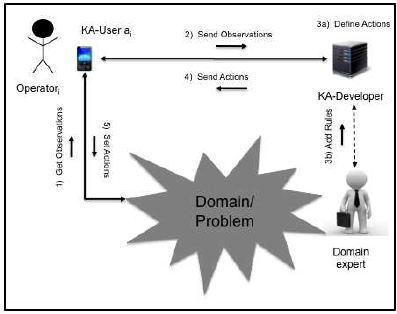
4.1 KAFKA Scenario
The typical KAFKA domain is shown in Figure 1,
where two kinds of roles are hypothesized: a KA–
User supporting a generic operator solving problems
and a KA–Developer, supporting a domain expert in
the elaboration of decision making processes. The
KA–User is characterized by a state, a collection of
quantitative and qualitative parameters (observations
on the domain) that can be measured by PDAs or eval-
uated by the expert according to a given reasoning.
This state can change over the time: thus, it is con-
tinuously checked by the system in order to discover
Figure 1: KAFKA scenario: Domain expert and operators
virtually communicate to solve a problem in a given do-
main.
modifications and take proper actions. The domain
expert can interact with the KA–Developer to update
the different KA elements.
4.2 Knowledge Artifacts
KAFKA Knowledge Artifact is described as a 3–tuple
hO,IN, TSi, where O is an ontology of the investi-
gated domain, IN is an Influence Net to represent
the causal dependencies among the ontology elements
and TS are task structures to represent how one or
more outputs can be produced by the system accord-
ing to a rule–based system strategy.
In the current KA model, the underlying ontology
is a taxonomy: the root is the description of the prob-
lem to be solved, the inner nodes are system inputs
or partial outputs and the leaves of the hierarchy are
effective outputs of the system.
The Influence Net model is a structured process
that allows to analyse complex problems of cause–
effect type in order to determine an optimal strategy
for the execution of certain actions, to obtain an opti-
mal result. The Influence Net is a graphical model that
describes the events and their causal relationships.
Using information based on facts and experience of
the expert, it is possible to analyze the uncertainties
created by the environment in which we operate. This
analysis helps the developer to identify the events and
relationships that can improve or worsen the desired
result. In this way you can determine the best strategy.
The Influence Net can be defined as a 4–tuple
hIS,PS,OS,ASi, where:
• IS is the input node set, i.e. the information
needed to the KBS to work properly;
• PS is the partial output node set, i.e. the collec-
tion of new pieces of knowledge and information
elaborated by the system to reach the desired out-
put;
• OS is the output node set, i.e. the effective an-
swers of the system to the described problem; out-
puts are values that can be returned to the user;
• AS is the set of arcs among the nodes: an arc be-
tween two nodes specifies that a causal relation-
ship exists between them; an arc can go from an
input to a partial node or an output, as well as from
partial node to another one or an output. More-
over, an arc can go from an output to another out-
put. Every other kind of arcs is not permitted.
Finally, Task Structures allow to describe in a
rule–based system way how the causal process de-
fined by a given IN can be modeled. Each task is
devoted to define computationally a portion of an In-
fluence Net: in particular, sub–tasks are procedures to
Time Evolving Expert Systems Design and Implementation: The KAFKA Approach
87
specify how a partial output is obtained, while tasks
are used to explain how an output can be derived from
one or more influencing partial outputs and inputs.
A task cannot be completed until all the sub–tasks
influencing it have been finished. In this way, the
TS modeling allows to clearly identify all the lev-
els of the system. The task and sub–task bodies are
a sequence of rules, i.e. LHS(LeftHandSide)− >
RHS(RightHandSide) constructs.
Each LHS contains the conditions that must be
verified so that the rule can be applied: it is a logic
clause, which turns out to be a sufficient condition
for the execution of the action indicated in the RHS.
Each RHS contains the description of the actions to
conduct as a result of the rule execution. The last
step of our model is then the translation of all the task
and sub–task bodies into production rules of a specific
language (Jess in our case).
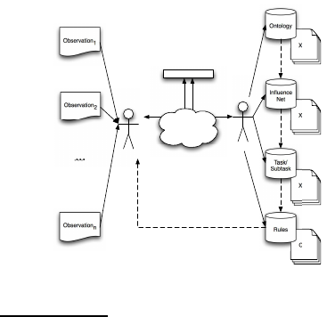
4.3 KAFKA Architecture
Every KA–User (i.e. the client in Figure 2) involved
in a problem solving activity is provided with an An-
droid application: this application communicates with
the KA–Developer (i.e. the server in Figure 2) by
means of an Internet connection. The KA–User sends
data serialized into a JSON
1
object. JSON is an
open standard format that uses human–readable text
to transmit data objects consisting of attribute–value
pairs. For this reason, it is very useful in KAFKA
to exchange facts between the client and the server,
being sure they are correctly interpreted. These data
are observations about the conditions of the problem
domain. The GSON
2
library has been integrated to
automatically convert Java objects (like shadow facts)
into their JSON representation.
Observation
1
Observation
2
Observation
n
XML
XML
XML
CLP
Ontology
Influence
Net
Task/
Subtask
Rules
Client
Server
JSON - GSON
Internet
Figure 2: KAFKA architecture: solid arrows represent con-
crete flows, whilst dashed ones represent virtual flows.
1
JavaScript Object Notation, see http://json.org/
2
See https://sites.google.com/site/gson/
gson-user-guide#TOC-Goals-for-Gson
Then, exploiting the Android primitives, it has
been possible to create a stable mechanism for the
communication with the server. In particular, the fol-
lowing tools were useful to implement the KA–User
in KAFKA:
• activities: a class that extends an Activity class is
responsible for the communication with the user,
to support him/her in setting the layout, assign-
ing the listeners to the various widgets (Android’s
graphical tools) and setting the context menu;
• listener: a class that implements the interface
OnClickListener is a listener. An instance of this
object is always associated with a widget;
• asyncTask: a class that extends AsyncTask is an
asynchronous task that performs some operations
concurrently with the execution of the user inter-
face (for example the connection to a server must
be carried out in a AsyncTask instance, not in an
Activity one);
The typical mechanism to interface the client and
the server is the following one: the Activity object
prepares the layout and sets the widgets’ listeners
and a container with the information useful for the
server; then, it possibly starts the AsyncTask instance
for sending the correct request to the server, passing
to it the previously created container. Before starting
the asynchronous task, in most cases, the listener ac-
tivates a dialog window that locks the user interface
in waiting for the communication with the server; the
AsyncTask predisposes the necessary Sockets for the
communication and then performs its request to the
server, sending the information about the case study
observation enclosed in the container. Before con-
cluding, it closes (dismisses) the waiting dialog win-
dow. The KA–Developer creates an instance of the
KA model (i.e. the collections of XML files for On-
tology, Influence Net and Task/Subtask in Figure 2)
for each active KA–User in communication with it.
Then, it executes the related rule–based system (i.e.
the collection of .clp files in Figure 2) and sends an-
swers, serialized into a JSON object, to the KA–User
that will be able to take the proper action.
At the current state of development, the rule–
based systems generated by a KA–Developerare writ-
ten in Jess 7.0: this means they cannot be directly
executed by a KA–User, since Jess 7.0 is not fully
supported by Android. Thus, the server is responsi-
ble for their execution. Anyway, it has been designed
to allow the serialization of .clp files too in the fu-
ture, when Jess will be runnable under Android (i.e.
when a stable version of Jess 8.0 will be released).
The server, once activated, can accept both requests
for the creation of a new system by a domain expert
KEOD 2015 - 7th International Conference on Knowledge Engineering and Ontology Development
88
and for the resolution of problems on the basis of ex-
isting rule–based systems by a user.
4.4 KAFKA Implementation
The implementation of the different elements com-
posing the knowledge engineering framework ex-
ploits the XML language (Sartori and Grazioli, 2014).
A proper schema has been developed for each of
them, as well as dedicated parsers to allow the user
to interact with them. These XML files contain all
the information necessary to compile rule–based sys-
tems: as previously stated, the Jess sintax has been
chosen to this scope.
4.4.1 Implementing Ontology, Influence Net and
Taks/Subtasks
Following the conceptual model briefly introduced in
the previous section, the first schema is the ontolog-
ical one, as presented below. The schema presents
opportune tags to specify inputs, where the name of
the input can be put (i.e. the hnamei tag in the code
below) together with a value for it (the hvaluei tag).
The hdescriptioni tag is used to specify it that input
should be modeled as a shadow fact or not. More-
over, it is possible to define an haf fectsi relationship
for each input, in order to explain how it is involved
in the next steps of the elaboration (i.e. which output
or partial output does it contribute to state?).
<ontology>
<name> ... </name>
<description> ... </description>
<input>
<name> ... </name>
<value> ... </value>
...
<affects> ... </affects>
...
</input>
<partialOutput>
<name> ... </name>
<value> ... </value>
...
<affects> ... </affects>
...
<influencedBy> ... </influencedBy>
...
</partialOutput>
<output>
<name> ... </name>
<value> ... </value>
...
<influencedBy> ... </influencedBy>
...
</output>
</ontology>
A partialOutput (i.e. an inner node between an
input and a leaf of the taxonomy) is limited by the
hpartialOutputi and h/partialOtuputi pair of tags.
The fields are the same as the input case, with the dif-
ference that a partial output can be influenced by other
entities too: this is the sense of the hinfluencedByi
tag. Finally, the houtputi tag allows to describe com-
pletely an effective output of the system, i.e. a leaf
of the taxonomy developed to represent the problem
domain. Output can be influenced by other elements
of the Ontology, i.e. inputs and partial outputs, but
the vice-versa is not valid (i.e. the haf fectsi relation-
ship is not defined on outputs). The following code
illustrates an example of how an Influence Net is pro-
duced. The taxonomy is bottom–up parsed, in order
to identify the right flow from inputs to outputs by
navigating the influenced by relationships designed by
the user. In this way, different portions of the system
under development can be described. Outputs, partial
outputs and inputs are bounded by arcs which specify
the source and the target nodes (the source and target
attribute respectively).
<influenceNet>
<name> ... </name>
<description> ... </description>
<root>
---------- Start Output List ----------
<output id = "id" value = "output from ontology">
</output>
...
---------- End Output List ----------
---------- Start partialOutput List ----------
<partialOutput id = "id" value = "partialOutput
from ontology">
</partialOutput>
...
----------- End partialOutput List ----------
----------- Start Input List -----------
<input id = "id" value = "output from ontology">
</input>
...
---------- End Input List -----------
---------- Start Arc List ----------
<arc id = "id" value = "name of the arc" source =
"id input or partialOutput" target = "id output
or partialOutput">
</arc>
...
</root>
</influenceNet>
Finally, an XML schema for the Task (Subtask ele-
ments of the framework are defined in the same way)
can be produced as follows. The parser composes a
XML file for each output considered in the Influence
Net. The input and subtask tags allow to define which
inputs and partial outputs are needed to the output rep-
resented by the Task to be produced. The body tag
is adopted to model the sequence of rules necessary
Time Evolving Expert Systems Design and Implementation: The KAFKA Approach
89
to process inputs and results returned by influencing
Subtasks: a rule is composed of an hifi ... hdoi con-
struct, where the if statement permits to represent the
LHS part of the rule, while the do statement concerns
the RHS part of the rule.
<task>
<name> ... </name>
<description> ... </description>
<input>
<element> Input from the ontology </element>
...
</input>
<body>
<subtask> subtask name </subtask>
...
<if> rule LHS </if>
<do> rule RHS </do>
...
</body>
<output>
<value> ... </value>
...
</output>
</task>
The XML files introduced above can be incorpo-
rated into dedicated decision support systems to guide
the user in the design of the underlying taxonomy, In-
fluence Net and Tasks/Subtasks. Moreover, it is pos-
sible to transform the Task into a collection of files
containing rules written for instance in the Jess lan-
guage.
4.4.2 Implementing Rules
Given the XML code for Task and Subtask Structures,
a rule file can be generated by means of opportune
parsers. In principle, every language for rule–based
system design can be exploited, but the current ver-
sion of KAFKA adopts Jess. The main reason for
this was the possibility to exploit the shadow fact con-
struct in the knowledge base to take care of its vari-
ability: basically, a shadow fact is an object integrated
into the working memory as a fact. For this reason, it
is possible to access it for value modifications from
every kind of application, and the inference engine
will understand the situation, activating a new running
of the expert system.
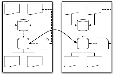
The shadow fact is fundamental to manage the
variable scenario in Figure 1: as shown in Figure 3 a
system transition from state S
i
to state S
j
can be due to
the observation of a not previously considered value
for one or more observations. At State
i
, Observation
n
is detected by the KA–User, that was not considered
by the current knowledge artifact. A new shadow fact
is then generated to take care of it (i.e. ShadowFact
n
),
and the KA–Developer is notified about the need for
State i
Task/
Subtasks
Observation
1
Observation
n
... ...
Rules
Shadow
Fact
n
?
Output
1
Output
m
...
?
State j
Task/
Subtasks
Observation
1
Observation
n
... ...
Rules
Shadow
Fact
n
Output
1
Output
m
...
?
Adding new Rules
Figure 3: Transition from a State i toa State j: ShadowFact
n
is not recognized in State
i
, for this reason, new rules are
added moving to State
j
, where ShadowFact
n
is known.
extending the rule set in order to properly manage that
value. In this way, the system moves from state S
i
,
where it is not able to reach a valid solution to the
problem, to state S
j
, where new rules have been added
to fill the gap.
On the other hand, when all the possible values
for every observation will be mapped into the set of
rules of an expert system, for example in the S
k
state,
that system will be considered stable, and the related
rules’ set will be able to generate a solution for every
possible configuration of inputs. Thanks to its intrin-
sically dynamic nature (it is a Java object), the shadow
fact is the most suitable technical artifact to take care
of such characteristics: by changing its value at run-
time, the inference engine will be able to run the
current expert system part whose behavior possibly
varies according to that change; in case of no solution,
the KA–Developer will be notified about the need for
extending both the knowledge artifact and the related
set of rules.
5 CASE STUDY
The case study was inspired by the STOP handbook
(S. Grimaz (coord.), 2010), supplied to the Italian Fire
Corps and Civil Protection Department of the Pres-
idency of Council of Ministers for the construction
of safety building measures for some building struc-
tures that have been damaged by an earthquake. In
case of disaster occurring, operators reach the site in
order to understand the event consequences and take
the proper actions to make safe both human beings
and buildings. The case study focused on two actions
typical of earthquakes, namely WallsÕ safety mea-
sures. This action aims at preventing further rotation
or bulging of the wall damaged during an earthquake.
It is important to notice that operators are provided
with standard equipment to those scopes, i.e. a set
KEOD 2015 - 7th International Conference on Knowledge Engineering and Ontology Development
90
of rakers and shores that can be useful in most situa-
tions. The main problem is to understand if this equip-
ment can be adopted in case of particularly disrupting
events: in fact, the situation found by the operators
continuously evolve from a state S
i
to a new state S
j
according to phenomena like aftershocks. The STOP
App has been thought for these situations, when op-
erators need more information to e.g. combine rakers
in order to sustain walls dramatically damaged by the
earthquake or shores to cover very large apertures.
The following sections will further explain how
the scenario has been effectively translated into a
computational system, focusing on how a Knowl-
edge Artifact has been created and instantiated. The
main goal of the STOP application has been the pos-
sibility to have faster answers by means of a collec-
tion of rule–base system that incorporates the STOP
handbook knowledge, where the operators can insert
the inputs to get outputs in a transparent way. An-
other important point is the possibility to extend the
STOP model when needed, adding rules to the KA–
Developer knowledge by means of an opportune in-
terface: as previously stated, the role of shadow facts
is crucial to this scope.
5.1 Walls’ Safety Measures: Modeling
Knowledge Involved
Rakers are devices adopted to prevent further rota-
tion or bulging of the wall damaged during an earth-
quake. There exist two main kinds of rakers: solid
sole and flying (S. Grimaz (coord.), 2010). Solid sole
rakers can be used when the conditions of the pave-
ment around the damaged walls are good, while fly-
ing rakers are useful when rubble is present. Due to
their morphology, solid sole rakers allow to distribute
the wall weight in a uniform manner along the whole
pavement, with greater benefits from the wall safety
point of view. Anyway, the possibility to concentrate
the wall sustain on smaller sections is important too,
especially when earthquakes intensity is so strong to
break windows or building frontages.
The other two information to fix are raker class
and dimensions. Raker class depends on the distance
between the sole and the position of the top horizon-
tal brace on the wall; raker dimensions can be estab-
lished starting from the raker class, the seismic class
related to the earthquake, the wall thickness and the
span between the raker shores. The values introduced
above constitute the set of system inputs that should
be properly used by the KA–Developer to elaborate
problem solutions. How these inputs are effectively
exploited and which relationships exist among them
are also important points to take care of.
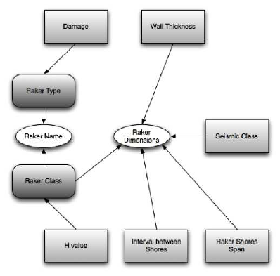
This is the goal of the Influence Net depicted in
Figure 4, which clearly identifies outputs and partial
elaborations in order to understand what is the rea-
soning process that allows to get outputs starting from
inputs. In particular, the type of raker (i.e. Solid Sole
or Flying) and the class of it can be considered as
outputs or partial outputs: they have been described
as partial outputs, since the final goal of the decision
making process is to choose a raker in terms of name
(that is R1, R2, R3 and so on) and dimensions. Raker
class and type are characteristics that allow defining
the name of the raker, but are not interesting for the
user.
Figure 4: The Influence Net diagram for Walls Safety case
study. Light gray rectangles are Inputs, Rounded Corner
Rectangles are Partial Outputs and Ovals are Outputs. The
arcs semantic is influenced–by.
The last part of knowledge acquisition and repre-
sentation is the definition of Tasks and Subtasks, in
order to specify how outputs can be obtained from in-
puts. As previously introduced, an XML file is pro-
duced for each output and partial output included into
the Influence Net. According to the designed schema,
these files contain a description of necessary inputs,
expected outputs and the body, i.e. the instructions
necessary to transform inputs into outputs. These in-
structions can be hif i ... hdoi constructs or invoca-
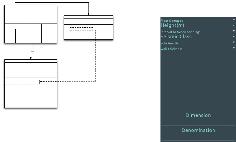
tions of influencing subtasks. Figure 5 shows a sketch
of the decision making process concerning a portion
of the case study Influence Net, starting from the
knowledge involved as provided by the STOP hand-
book: the dashed arrow between Class attributes in
the Subtask and Task bodies specifies the precedence
relationship between them (i.e. the Task must wait
for Subtask completion before starting). The result
returned by the subtask is used to value the DIMEN-
SIONS output of the task to be returned to the user as
Time Evolving Expert Systems Design and Implementation: The KAFKA Approach
91
IF (H Value >= 2 AND H Value < 3)
DO Class = R1
...
IF (H Value > 7)
DO Class = S
Input: H Value
Output: Class
SubTask: rakerClass
Class = rakerClass(H Value)
IF (Thickness Wall < 0.6 AND
Seismic Class = A AND
Raker Shores Span = 1.5 AND
Interval Between Shores = 1.5 AND
Class = R1)
DO (Dimensions = 13X13)
...
Input: Thickness Wall
Input: Interval Between Shores
Input: Seismic Class
Input: Raker Shores Span
Output: Dimensions
Task: rakerDimensions
R1
H Value >= 2
H Value < 3
Wall Thickness <= 0.6 m
seismic class class A
Interval between
shores
= 1.5 m = 2.5 m
Raker
shores
span
< 1.5 m
= 1.5 m
> 1.5 m
< 2.0 m
13 X 13 13 X 13
13 X 1315 X 15
Figure 5: A sketch of the decision making process made by
the KA–Developer according to the case study IN in Fig-
ure 4. The table on the figure top is derived from the STOP
handbook: raker type (R1) is determined by the connected
subtask; dimensions of the raker are calculated by the con-
nected task.
a computational result. The task body is a sequence of
IF...DO rules, where different patterns are evaluated
in the LHS and the RHS propose an opportune value
for the output. The semantic of the rule shown in Fig-
ure 5 is the following: if the
thickness of the wall
to
support is
less than 0.6 m
and the earthquake
seismic
class
is
A
and
raker shores span
is
1.5 m
and the
in-
terval between shores
is
1.5 m
and the
raker class
is
R1
, the
dimensions
of the raker should be
13X13
m
2
.
Similar considerations can be made for the other
task of the case study, namely rakerName, based on
the Raker Name node of the Influence Net, and influ-
enced by the rakerClass and rakerType Subtasks.
5.2 The KA–User and the
KA–Developer: Two Android
Clients
Every operator involved in the emergency procedures
to make safe buildings and infrastructures is provided
with an Android application on his/her smartphone:
this application communicates with the server via
the client–server architecture introduced above. Each
KA–User sends the server data about the conditions of
the site it is analyzing: according to the STOP hand-
book, these data allow to make considerations about
the real conditions of the building walls and openings
after the earthquake, in order to understand which
raker or scaffolding to adopt. Figure 6 presents the
GUI for introducing inputs to configure rakers in the
first case study: according to the conceptual model
described so far, the KA–User guides the user in or-
der to avoid mistakes during parameters set up.
Figure 6: The GUI provided by the KA–User to set up in-
puts for the Walls’ Safety case study and to present Raker’s
configuration results to the user.
The KA–User converts the values into GSON in-
stances, which will be sent to the server for elabo-
ration, waiting for answers from it. Values are sug-
gested by the application when available (e.g. in the
case of Damaged floor, Seismic class, Sole length and
Wall thickness), i.e. when the STOP handbook pro-
vides guidelines. Otherwise, the operator measures
them and they will be properly interpreted by the
server according to the Knowledge Artifact provided
by the KA–Developer. This operation mode is sharply
different from that of a traditional Expert System:
the domain expert associated to the KA-Developer
could immediately (i.e. dynamically!) add new rules
to the Knowledge Artifact, in order to give sugges-
tions fitting the real conditions observed on-site by
the KA–User. This is possible thanks to the adop-
tion of shadow facts for representing observations in
KAFKA: when results are provided by the server,
the KA–User presents them to the operator through
the same GUI in Figure 6. Both outputs present in
the case study Influence Net (see Section 5.1) are re-
turned, i.e. raker name, that is a combinationof partial
outputs raker class (value R1) and raker type (value
Flying) and dimensions.
If no output is available, due to the lack of knowl-
edge in the KA, as shown in Figure 7, the KA–
Developer can support the domain expert to complete
the knowledge base: Figure 8 shows the provided
GUI.
Then, the rule–based system can be executed
KEOD 2015 - 7th International Conference on Knowledge Engineering and Ontology Development
92
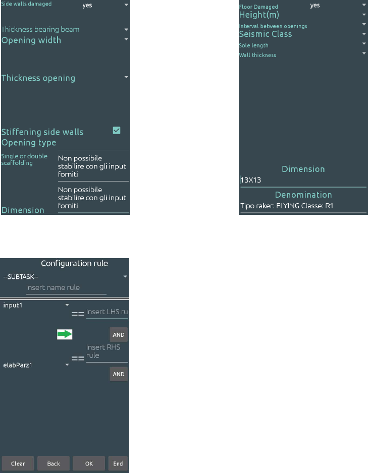
Figure 7: No output available due to the observations pro-
vided by the KA–User: new rules must be added to the
knowledge base.
Figure 8: The GUI provided by the KA–Developer to the
domain expert to introduce new rule in the knowledge base.
again by the KA–User, being sure that valid values
will be obtained in output, as shown in Figure 9.
The system can be run again on different configu-
rations of input, producing new outputs according to
the KA model: if necessary, new rules can be added
moving the system from a stable state S
i
to a new sta-
ble state S
j
as described in section 4.4.2. In this way,
the rule–based system is iteratively built up according
to new discoveries made by the user on the applica-
tion field.
Figure 9: After the domain expert intervention, the KA–
User is able to provide the user with an output.
6 CONCLUSIONS
This paper addressed the problem of time evolv-
ing expert systems design and implementation: the
KAFKA approach has been presented from both the
theoretical and practical point of view. A unique fea-
ture of KAFKA is its developmentunder Android OS,
that allows to use it in many contexts characterized by
ubiquity of inputs and scalability of problem descrip-
tions.
The work on the KAFKA framework is develop-
ing on multiple directions: from the theoretical point
of view, we are moving from KAFKA to KAFKA
2
, by
substituting the IN Knowledge Artifact with Bayesian
Networks (BN) (Melen et al., 2015) to represent pro-
cedural knowledge; from the practical point of view,
we are extending the KA–User side to detect observa-
tions by means of wearable devices.
The first point will allow to automatically gener-
ate .clp files from an initial probability distribution; in
this way, the KA–Developer will be potentially able
to discover transitions from S
i
to S
j
on its own, with
no explicit need for domain expert intervention. The
second point will allow to extend the applicability of
KAFKA to those domains characterized by frequent
and continuous values update.
In particular, we are planning to use KAFKA
2
in a
collaboration with psychologists in the ALS domain,
where two kinds of roles are hypothesized (see Figure
10: a KA-User supporting a generic Patient/Caregiver
being subject to a given therapy and a KA-Developer,
Time Evolving Expert Systems Design and Implementation: The KAFKA Approach
93
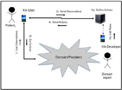
Figure 10: A specialization of the general scenario pre-
sented in Figure 1 in the ALS domain.
supporting a Domain Expert, like a psychologist or a
doctor. The KA-User is characterized by a state, a col-
lection of quantitative (e.g. heart rate) and qualitative
(e.g. self-efficacy) parameters that can be measured
by PDAs or evaluated by the expert according to a
decision making process. This state can change over
the time: for this reason, it is continuously checked
by the system in order to discover potentially nega-
tive evolutions and take proper actions. The domain
expert can interact with the server to design the KA el-
ements, i.e. the ontology, the Bayesian Network and
the initial rule-based system. Then, the KA-User can
send observations about the current state of its Pa-
tient/Caregiver to the server, which will execute the
rules to suggest a proper therapy. The KA-User will
provide it to the Patient/Caregiver and periodically
send new observations to the server. In case of signif-
icant changes in the state detection, the BN compo-
nent of the KA will be able to automatically generate
new rules: these rules can be evaluated by the expert,
through the related KA-Developer.
REFERENCES
Angele, J., Fensel, D., Landes, D., and Studer, R. (1998).
Developing knowledge-based systems with mike. Au-
tomated Software Engineering, 5(4):389–418.
Bonastre, A., Ors, R., and Peris, M. (2001). Distributed
expert systems as a new tool in analytical chemistry.
TrAC - Trends in Analytical Chemistry, 20(5):263–
271.
Butler, T., Feller, J., Pope, A., Emerson, B., and Murphy,
C. (2008). Designing a core it artefact for knowl-
edge management systems using participatory action
research in a government and a non-government or-
ganisation. The Journal of Strategic Information Sys-
tems, 17(4):249–267.
Holsapple, C. W. and Joshi, K. D. (2001). Organiza-
tional knowledge resources. Decision support sys-
tems, 31(1):39–54.
Kitamura, Y., Kashiwase, M., Fuse, M., and Mizoguchi, R.
(2004). Deployment of an ontological framework of
functional design knowledge. Advanced Engineering
Informatics, 18(2):115–127.
Melen, R., Sartori, F., and Grazioli, L. (2015). Modeling
and understanding time-evolving scenarios. In Pro-
ceedings of the 19th World Multiconference on Sys-
temics, Cybernetics and Informatics (WMSCI 2015) -
Volume I, pages 267–271.
Nalepa, G. and Lig˛eza, A. (2010). The hekate methodol-
ogy. hybrid engineering of intelligent systems. Inter-
national Journal of Applied Mathematics and Com-
puter Science, 20(1):35–53.
Niedderer, K. and Reilly, L. (2010). Research practice in
art and design: Experiential knowledge and organised
inquiry. Journal of Research Practice, 6(2).
Norman, D. A. (1991). Cognitive artifacts. In Designing
interaction, pages 17–38.
Omicini, A., Ricci, A., and Viroli, M. (2008). Artifacts
in the a&a meta-model for multi-agent systems. Au-
tonomous agents and multi-agent systems, 17(3):432–
456.
Ruiz-Mezcua, B., Garcia-Crespo, A., Lopez-Cuadrado,
J. L., and Gonzalez-Carrasco, I. (2011). An expert
system development tool for non ai experts. Expert
Systems with Applications, 38(1):597–609.
Rybina, G. V. and Deineko, A. O. (2011). Distributed
knowledge acquisition for the automatic construction
of integrated expert systems. Scientific and Technical
Information Processing, 38(6):428–434.
S. Grimaz (coord.), e. a. (2010). Vademecum STOP. Shoring
templates and operating procedures for the support of
buildings damaged by earthquakes. Ministry of Inte-
rior - Italian Fire Service.
Salazar-Torres, G., Colombo, E., Da Silva, F. C., Noriega,
C., and Bandini, S. (2008). Design issues for knowl-
edge artifacts. Knowledge-based systems, 21(8):856–
867.
Sartori, F. and Grazioli, L. (2014). Modeling and under-
standing time-evolving scenarios. In Metadata and
Semantics Research - 8th Research Conference, MTSR
2014, Karlsruhe, Germany, November 27-29, 2014.
Proceedings, pages 60–67.
Schmidt, K. and Simone, C. (2000). Mind the gap. Towards
a unified view of CSCW. COOP, pages 205–221.
Schreiber, G. (2013). Knowledge acquisition and the web.
International Journal of Human Computer Studies,
71(2):206–210.
Schreiber, G., Wielinga, B., de Hoog, R., Akkermans, H.,
and Van de Velde, W. (1994). Commonkads: A com-
prehensive methodology for kbs development. IEEE
expert, 9(6):28–37.
Surif, J., Ibrahim, N. H., and Mokhtar, M. (2012). Con-
ceptual and procedural knowledge in problem solving.
Procedia - Social and Behavioral Sciences, 56:416–
425.
Yan, H., Jiang, Y., Zheng, J., Fu, B., Xiao, S., and Peng,
C. (2004). The internet-based knowledge acquisition
KEOD 2015 - 7th International Conference on Knowledge Engineering and Ontology Development
94
and management method to construct large-scale dis-
tributed medical expert systems. Computer Methods
and Programs in Biomedicine, 74(1):1–10.
Time Evolving Expert Systems Design and Implementation: The KAFKA Approach
95
