Inedited SVM Application to Automatically Tracking and
Recognizing Arm-and-Hand Visual Signals to Aircraft
Giovanni Saggio
1
, Francesco Cavrini
2
and Franco Di Paolo
1
1
Department of Electronic Engineering, University of Rome “Tor Vergata”, via del Politecnico 1, Rome, Italy
2
Captiks S.r.l., via Giacomo Peroni 442-444, Rome, Italy
Keywords: Visual Signalling, Sensory Glove, SVM.
Abstract: An electronic demonstrator was designed and developed to automatically interpret the signalman’s arm-and-
hand visual signals. It was based on an “extended” sensory glove, which is a glove equipped with sensors to
measure fingers/wrist/forearm movements, an electronic circuitry to acquire/condition/feed measured data
to a personal computer, SVM based routines to classify the visual signals, and a graphical interface to
represent classified data. The aim was to furnish to the Italian Aircraft Force a tool for ground-to-ground or
ground-to-air communication, which can be independent from the full view of the vehicle drivers or aircraft
pilots, and which can provide information redundancy to improve airport security.
1 INTRODUCTION
According to the International Code of Signals, by
National Imagery and Mapping Agency (United
States Edition, revised 2003), the Visual Signalling
(VS) is any method of communication, the
transmission of which is capable of being seen. The
VS can be implemented by means of different
methods, among which the arm-and-hand based one,
treated here.
This method of signalling is mandatory for
communication of deaf people, can generally
improve communication in task collaboration
(Gander, 1996), and becomes strategical for
particular communications when radios cannot be
used or are unavailable. Inter alia, here we consider
a VS application suitable to meet the requirements
of the “Armaereo” (a Military Aircraft Force of the
Italian Ministry of Defence), which funded our
research. However, the basic idea can be easily
extended to any field where VS is standardized, as it
occurs for the Army (reference: visual signals for
armor fighting vehicles, GTA 17-02-019), for the
Navy and Marine (reference: Offensive combat I and
combat signs, by United States Marine Corps, TACT
3022, Apr 2011), for the Road rules (as an example
of reference: Washington State Legislature, Rules of
the road, Chapter 46.61.310), and for sport activities
(as an example of reference: Basic Officials Manual
of the USA Hockey, updated August 2013).
The VS refers to code meanings related to
specific vocabulary, receipting, acknowledging and
identification procedures (Visual Signals,
Department of the army, FM 21-60). Here we
consider the ground-to-ground or ground-to-air
visual signal communications between the
signalman and the vehicles or aircrafts, with the aim
of furnishing an automatic electronic way of
interpreting the signalman’s visual signals, so to
replicate the decoded signal meaning inside the
military vehicle or inside the aircraft, allowing
double check to the driver or to the pilot. This
system has the advantages of being independent on
the full view of the driver or the pilot, of offering
information redundancy for management or security
improvement, and of allowing information recording
for realizing a sort of a “black box airport runway”,
similar to the well-known “black box flight
recorder”.
The signalman is in charge of communicating
with standard signals (among which: cut engine(s),
hook-up complete, release, move right/ left/ ahead/
rearward/ downward/ upward, depart, land, do not
land) or emergency signals (among which: ok,
affirmative, negative, do not attempt to land, stop).
These signals are arm-and-hand based and can be
tracked by means of different technologies.
Currently, the mostly adopted method of tracking
relies on optical cameras (Song et al., 2011), but our
project intended to avoid any camera, so to be
Saggio, G., Cavrini, F. and Paolo, F..
Inedited SVM Application to Automatically Tracking and Recognizing Arm-and-Hand Visual Signals to Aircraft.
In Proceedings of the 7th International Joint Conference on Computational Intelligence (IJCCI 2015) - Volume 3: NCTA, pages 157-162
ISBN: 978-989-758-157-1
Copyright
c
2015 by SCITEPRESS – Science and Technology Publications, Lda. All rights reserved
157
independent by camera distance, camera occlusion,
number of cameras, and insufficient lighting. In
particular, our system implemented a sort of
“extended” sensory glove, that is, a glove equipped
with sensors to measure not only flex/extensions of
the fingers, but also wrist and forearm movements.
The sensory glove has been finding very
different applications, among which the real-time
control of a granular sound synthesis process
(Costantini et al., 2010), the monitoring of hand
rehabilitation (Park et al., 2009; Mohan et al., 2013)
or clinical hand assessment (Williams et al., 2000),
the human-computer interaction (Saggio et al., 2012;
Berlia and Santosh, 2014), the sign-to-language
conversion (Cavallo et Saggio, 2014), the objective
surgical skill assessment (Saggio et al., 2015), the
serious games for training of rescue teams
(Mugavero et al., 2014), the tele-robotic
manipulations for astronauts (Saggio and Bizzarri,
2014), and so on. As far as we know, this is the first
time the sensory glove is utilized for Aircraft Force
or Army purposes.
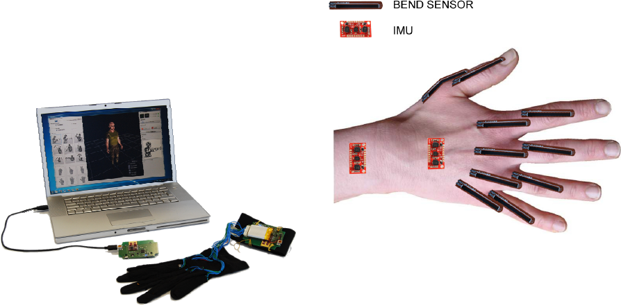
Figure 1: The “extended” sensory glove, the electronic
circuitry (both the source and the receiving one), the
virtual representation on a personal computer.
Here, we present an electronic framework, made of:
an “extended” sensory glove, an electronic circuitry,
a suitable classifier, and a virtual representation. The
framework was aimed to measure, record, recognize
and virtually represent the arm-and-hand visual
signals. Figure 1 shows the ensemble.
2 MATERIALS AND METHODS
The arm-and-hand tracking framework consisted of
hardware and software levels. In particular, we
distinguish a sensory glove and an electronic
conditioning circuitry for the so termed “source sub-
system”; an electronic receiving circuitry, a
mathematical classifier, and a virtual avatar
representation for the so termed “receiving sub-
system”.
2.1 The Sensory Glove
Our “extended” sensory glove includes a supporting
Lycra®-based glove equipped with ten
flex/extension sensors place on-top of the
metacarpo-phalangeal (MCP) and proximal-inter-
phalangeal (PIP) joints of each fingers, and two 6
degree-of-freedom (DoF) inertial measuring units
(IMUs), respectively necessary to measure the wrist
and forearm movements (Figure 2). Total source
signals were then 10+2x6=22.
Figure 2: Sensors placings: ten flex sensors on-top of the
MCP and PIP joints, one 6DoF IMU on the dorsal aspect
of the hand, and one 6DoF IMU on the forearm. The
supporting glove is not showed here for clarity reasons.
We did not measure the distal-inter-phalangeal
(DIP) joints since their flex/extension capabilities
are normally correlated to the PIP ones in known
percentages (Ghosh, 2013).
We used ten flex/extension sensors termed
“Bend Sensors®”, (by Flexpoint Sensor Systems
Inc., Draper, Utah, USA), adopted because of their
lightness and suitable repeatability and reliability
characteristics previously measured and reported
(Saggio and Bizzarri, 2014).
The two IMUs were the Sparkfun Razor ones (by
SparkFun Electronics, Niwot, Colorado, USA), each
with a 3-axis accelerometer and a 3-axis gyroscope.
2.2 The Electronic Circuitry
For the electronic circuitry we can distinguish the
“source” and the “receiving” subsystems.
NCTA 2015 - 7th International Conference on Neural Computation Theory and Applications
158
Let’s start considering the source-subsystem
(Figure 3a) necessary to acquire signals from the
sensors, to provide A/D conversions, and to
wired/wireless transmit data to the receiving-
subsystem. The wired transmission is intended for
testing purposes, while the wireless one to be in-
field adopted.
Resistance values from the ten flex sensors have
been converted into voltage values by means of an
equal number of voltage dividers, while voltage
values from the IMUs fed directly the circuitry. The
core of the source-subsystem was the integrated
circuit PIC18F47J53 (by Microchip, Chandler, AZ,
US), 48Mhz-clocked, capable of 12bit A/D
conversion.
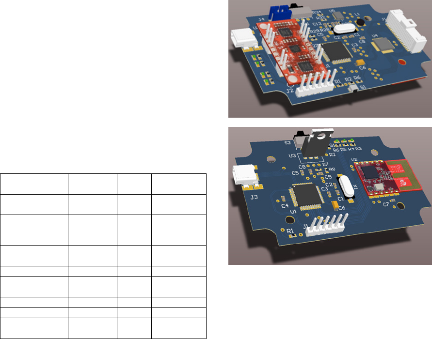
Table 1: Speed, range and consumption transmission
values among different protocols/standards.
Protocol/
Standard
Speed Range
Consumption
[mW]
IEEE802.15.4 /
ZigBee
20-250[kbps] <1km 40
Bluetooth-
Bluetooth Smart/
IEEE802.15.1
1-24 [Mbps] <100m 200
IEC62591/
WirelessHART
250 [kbps] <100m 40
ISA100.11a 250 [kbps] <100m 40
DASH7
27.7-200
[kbps]
<10km
1
Z-WAVE 10-40 [kbps] <300m 80
ANT 1 [Mbps] <30m 40
Wavenis
4.8-100
[kbps]
<200m 80
This IC offer only 10 analog inputs so that, in order
to acquire all the 22 signals from the extended
sensory glove, we used a 2x16 channel multiplexer,
the ADG726 (by Analog Devices, Norwood, MA,
USA) (its 10 spare input channels can be used for
eventually additional requirements).
Requests for the wireless protocol included short
(or medium) transmission range, low-medium
transmission speed, low-power consumption, and
scalability so to handle data of up to four sensory
gloves at a time, all in an auto user-independent
configuration mode. To respond to these requests,
we analysed different protocols/standards, in
particular the Bluetooth and Bluetooth smart
/
IEEE802.15.1, the IEC62591/ WirelessHART, the
ISA100.11a, the DASH7, the Z-Wave, the ANT, the
Wavenis, and the IEEE802.15.1/ ZigBee. Table 1
reports a comparison among speed, range and
consumption of the aforementioned protocol/
standards. The IEEE802.15.1/ ZigBee was our
choice, since it better covers the commitment
requirements.
(a)
(b)
Figure 3: The electronic circuitry, designed using an
electronic design automation (EDA) tool by Altium
Designer (by Altium, Belrose, NSW, Australia), of the (a)
source-subsystem and of the (b) receiving-subsystem.
Transmission security was not a mandatory
parameter for our purposes; anyway the
aforementioned protocols can be considered
reasonably “similar” from a cryptography point of
view. The interested reader can find a survey
comparison in Gomez and Paradells (2010).
Our wireless transmission was then obtained
with the IEEE 802.15.4 radio transceiver module
MRF24J40MA (by Microchip, Chandler, AZ, USA),
which allows a 0dBm transmission within a 100
meters range.
The DC power supply was realized with a Li-Ion
single-cell battery, charged and controlled by the IC
BQ25015 (by Texas Intruments, Dallas, TX, USA),
which includes a DC-DC buck converter capable of
300mA @3,3V.
Let’s now consider the receiving-subsystem
(Figure 3b), necessary to receive signals and to feed
them, via USB port, to the personal computer. It was
based on the same integrated circuit MRF24J40MA
of the source-subsystem. The USB transmission was
based on the inner full-speed module of a second
Inedited SVM Application to Automatically Tracking and Recognizing Arm-and-Hand Visual Signals to Aircraft
159
PIC18F47J53. The DC power supply was obtained
from the USB port, with its 5V reduced to the
necessary 3.3V adopting an LDO voltage regulator.
2.3 Set of Visual Signals
The visual signals we intended to discriminate come
from the Field Manual No. 21-60 – Visual Signals,
by Defence Department, USA, 1987.
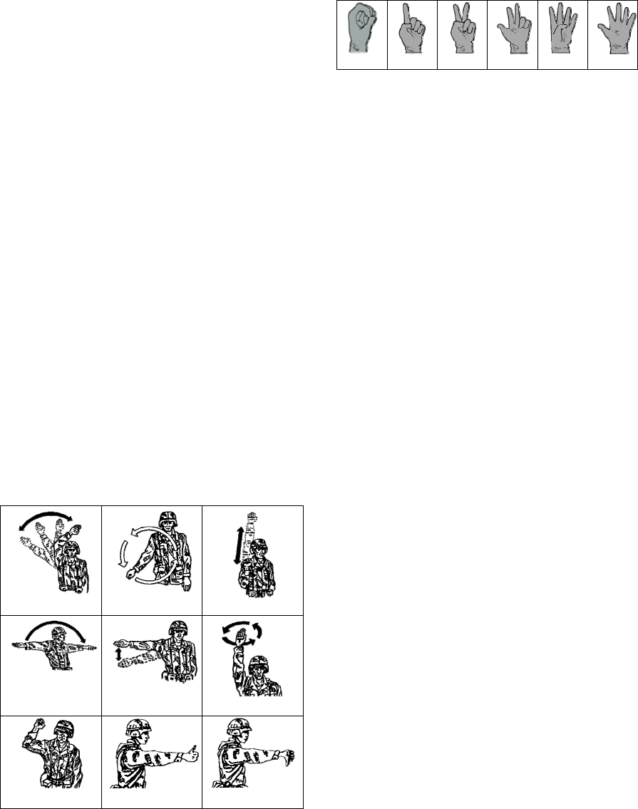
In particular we selected the arm-and-hand
signals for ground forces, used for controlling
vehicle drivers (Figure 4 a, b, c, d, e), for combat
formations (Figure 4 a, c, e, f), for patrolling (Figure
4 g), for recovery operations (Figure 4 b, h, i). In
addition, we considered to recognize six numbers
(from 0 to 5) represented by the hand, as in Figure 5.
These particular set of visual signals were
considered as the most representative for our
purposes, and included both static (maintained for at
least 3secs) than dynamic (repeated cycling at least
three times) gestures.
In order to recognize the dynamic visual signals,
i.e. the signals performed with arm-and-hand
moving and cycling to represent a gesture (Figure
4a-g), it was necessary to acquire electric signals
from all the sensors of the “extended” sensory glove,
but in order to recognize the static visual signals, i.e.
the signals performed keeping the arm-and-hand in a
static pose (Figure 4 h and i, Figure 5a-f), data from
IMUs were not necessary, therefore omitted.
(a)
(b)
(c)
(d)
(e)
(f)
(g)
(h)
(i)
Figure 4: Visual signals selected as representative for our
application, in particular: (a) attention or column, (b) start
engine or in haul the main winch, (c) increase speed or
rush, (d) advance, (e) slow down or quick time, (f) rally or
coil, (g) freeze, (h) ok, (i) nack.
(a)
(b)
(c)
(d)
(e)
(f)
Figure 5: Hand visual signals performing six numbers,
from 0 to 6.
2.4 Classifier
We intended to discriminate an arm-and-hand
gesture within a subset of visual gestures, and this
was possible by means of a suitable classifier.
This classifier could better perform when
preceded by pre-processing and feature extraction
phases. The pre-processing phase was aimed at
reduction of the undesired noise components by
means of digital IIR (Infine Impulse Response)
filtering. The feature extraction phase involved the
use of Fourier and Wavelet Transforms (Walker,
2008), and the calculation of statistical quantities
(e.g. energy, mean value, variance).
Concerning the classifier, among the mostly
adopted ones for recognition of human upper limb
posture and movement, we may include Artificial
Neural Network (ANN) (Mitra and Acharya, 2007),
Hidden Markov Model (HMM), and Support Vector
Machine (SVM) (He, 2011). The latter was here
selected as the most suitable for our purposes for
some of its peculiarities, in particular: its lower
tendency to overfitting (compared, for instance, to
ANN), and its good performance even if the data set
used in the learning phase is of contained dimension.
The metrics we used to evaluate the SVM
performances involved the Accuracy=C/T (C:
number of correctly classified trials, T: total number
of trials), the ErrorRate=E/T (E: number of wrongly
classified trials), the AbstentionRate=A/T (A:
number of abstentions).
2.5 Virtual Representation
We implemented software routines to reveal events
of connection of new sensory gloves (up to four), to
allow training and testing protocols, to acquire and
store data from the classifier, to present a graphical
interface (GUI, Figure 6) with interactive commands
for the user, and to virtually represent, via human
avatar, the movements related to the recognized
visual commands by the signalman.
NCTA 2015 - 7th International Conference on Neural Computation Theory and Applications
160
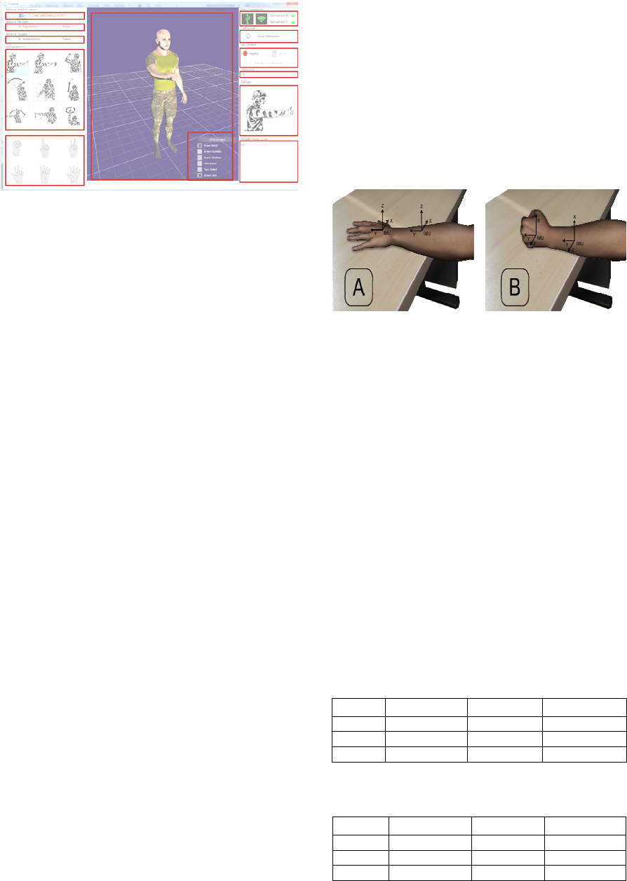
Figure 6: The graphical user-friendly pc-interface for
training and testing purposes. On the right column the
recognized gesture, on the middle column the animation of
the selected gesture via human avatar.
2.6 Training/Testing Protocol
Three subjects took part in the experimental
evaluation of the system. They were male 22-35
aged (average 27.6) right handed, with no motor or
intellectual limitations.
Our training/testing procedure started with a
calibration phase, which consisted in dressing the
sensory glove, and posing the hand in a full-open
(Figure 7a) and full-closed (fist, Figure 7b) position.
The two positions have to be maintained for two
seconds each, to allow the acquisition of a sufficient
number of sample data, from all the sensors, further
averaged.
During full-open/full-closed hand position
(Figure 7a/b), we measured both the
minimum/maximum electric values (resistances
converted into voltages) of each of the ten flex
sensors, and the electrical values (voltages) coming
from the x,y/z axis of the accelerometers and
gyroscopes of both IMUs.
The training/testing protocol always started from
the same condition, that is, the user was standing-up
with his/her arms along the body, and followed these
steps:
1. Glove dressing and calibration;
2. Training: three replays of each arm-and-hand
visual signal;
3. Glove removal and rest period;
4. Glove dressing and calibration;
5. Training: two replays of each arm-and-hand
visual signal;
6. Testing: five replays of all the visual signals;
7. Glove removal and rest period;
8. Glove dressing and calibration;
9. Testing: five replays of all the visual signals.
For the number postures we used a training/testing
protocol identical to the one described above. It
follows that, both for visual signals and numbers, we
acquired 5 training repetitions and 10 testing
repetitions of each posture/gesture. We feel it is
worth to stress that both training and test data has
been acquired in two distinct settings, i.e. after glove
removal and re-dressing, so to improve the
generalization capability of the classifier (during
learning) and better estimate performance in a real-
usage scenario (during testing).
Figure 7: The two hand poses (flat hand and fist) for the
calibration steps. The sensory glove is omitted in the
figure for clarity reasons.
3 RESULTS AND DISCUSSION
Table 2 and Table 3 show the system performance in
visual signals (Figure 4) and number recognition
(Figure 5), respectively. It is possible to observe that
in the latter task the classifier obtained optimal
performance, i.e. 100% accuracy, for all of the
involved subjects. In visual signals recognition,
performance was also close to optimal. In fact,
subject A reached 100% accuracy, and subjects B
and C obtained an high accuracy (above 95%) with
no errors but only abstentions. This is of particular
importance in all those scenarios in which the wrong
recognition of a signal could result in damage to
persons and/or things.
Table 2: Classifier performances related to the command
gestures.
Subject Accuracy(%) ErrRate(%) AbstRate(%)
A 100 0 0
B 97.78 0 2.22
C 95.56 0 4.44
Table 3: Classifier performances related to the gestures of
numbering.
Subject Accuracy(%) ErrRate(%) AbstRate(%)
A 100 0 0
B 100 0 0
C 100 0 0
Inedited SVM Application to Automatically Tracking and Recognizing Arm-and-Hand Visual Signals to Aircraft
161
4 CONCLUSIONS
Here we designed and developed a camera-free arm-
and-hand tracking framework, and implemented
SVM-routines capable to interpret signalman’s
gestures, so to obtain an automatic tool not prone to
human misinterpretation.
Preliminary experimental results with 3 subjects
have been quite encouraging (100% mean accuracy
for the number recognition task and over 97% mean
accuracy for visual signals identification) and thus
motivate us for a further investigation involving a
greater number of users and, possibly, real-time
continuous-recognition too. Future work will also
concentrate on the investigation of in-situ usability,
i.e. in a real or realistic environment.
ACKNOWLEDGEMENTS
This work was funded by the “Armaereo”
(Direzione Generale degli Armamenti Aeronautici,
Ministero della Difesa), Contract #a2009.90, for
which we would like to thank T.Col. GArn Aldo
Spagnolini and T.Col. GArn Salvatore Vignola.
REFERENCES
Berlia R., Santosh P., Mouse Brace: A convenient
computer mouse using accelerometer, flex sensors and
microcontroller. In: Contemporary Computing and
Informatics (IC3I), International Conference on:
IEEE) pp 558-61, 2014.
Cavallo P., Saggio G., Conversion of Sign Language to
Spoken Sentences by means of a Sensory Glove,
Journal of Software, Vol 9, No 8 (2014), 2002-2009,
Aug 2014.
Costantini G., Todisco M., Saggio G., A Cybernetic Glove
to Control a Real Time Granular Sound Synthesis
Process, in: Proceedings of the International Multi-
Conference on Complexity, Informatics and
Cybernetics (IMCIC), Orlando, Florida USA, 2010.
Song Y., Demirdjian D., Davis R., Tracking body and
hands for gesture recognition: Natops aircraft handling
signals database, in: Proceedings of the 9th IEEE
International Conference on Automatic Face and
Gesture Recognition, 2011.
Ghosh S., Capturing human hand kinematics for object
grasping and manipulation, Thesis submitted to the
Office o0f Graduate Studies of Texas and A&M
University, for the Degree of Master of Science, 2013.
Gomez C., Paradells J., Wireless home automation
networks: A survey of architectures and technologies,
in IEEE Communications Magazine, vol. 48, no. 6, pp.
92-101, 2010.
He Z., Accelerometer Based Gesture Recognition Using
Fusion Features and SVM, Journal of Software, vol. 6,
no. 6, 2011.
Mitra S. and Acharya T., Gesture Recognition: A Survey,
IEEE Transactions on Systems, Man, and Cybernetics,
Part C: Applications and Reviews, vol. 37, no. 3, pp.
311 –324, May 2007.
Mohan A., Devasahayam S. R., Tharion G., George J., A
Sensorized Glove and Ball for Monitoring Hand
Rehabilitation Therapy in Stroke Patients. In: India
Educators' Conference (TIIEC): IEEE) pp 321-7.
Park C-Y, Bae J-H, Moon I., Development of wireless
data glove for unrestricted upper-extremity
rehabilitation system. In: ICCAS-SICE, 2009: IEEE)
pp 790-3.
Saggio G., Lagati A., Orengo G., Wireless Sensory Glove
System developed for advanced Human Computer
Interface, International Journal of Information Science
2012, 2(5): 54-59.
Saggio G., Bizzarri M., Feasibility of Teleoperations with
Multi-Fingered Robotic Hand for Safe Extravehicular
Manipulations, Aerospace Science and Technology 39
(2014) 666–674.
Saggio G., Lazzaro A., Sbernini L., Carrano F. M., Passi
D., Corona A., Panetta V., Gaspari A. L., Di Lorenzo
N., Objective Surgical Skill Assessment: An Initial
Experience by Means of a Sensory Glove Paving the
Way to Open Surgery Simulation?, Journal of
Surgical Education, 2015.
Walker J. S., A Primer on Wavelets and Their Scientific
Applications, 2nd ed. Chapman and Hall/CRC, 2008.
Williams N. W., Penrose J. M. T., Caddy C. M., Barnes
E., Hose D. R., Harley P., A goniometric glove for
clinical hand assessment construction, calibration and
validation, Journal of Hand Surgery (British and
European Volume) 25 200-7, 2000.
NCTA 2015 - 7th International Conference on Neural Computation Theory and Applications
162
