UML Activity Diagrams for OWL Ontology Building
Joanna Isabelle Olszewska
School of Computing and Technology, University of Gloucestershire, The Park, Cheltenham, GL50 2RH, U.K.
Keywords:
UML, Activity Diagram, OWL, Ontology Design, Knowledge Engineering, Software Engineering.
Abstract:
Building efficiently an ontology is a crucial task for most of the applications involving knowledge represen-
tation. In particular, applications dealing with dynamic processes directly shaping the ontological domain
need the conceptualization of complex activities within this domain. For this purpose, we propose to develop
an OWL ontology based on UML activity diagrams. Indeed, the Unified Modeling Language (UML) is a
well-known visual language widely adopted for software specification and documentation. UML consists in
structure as well as behaviour notations such as activity diagrams which describe the flow of control and data
through the various stages of a procedure. Our approach has been successfully validated in a study case of an
ontology with a publication repository domain.
1 INTRODUCTION
Ontologies are widely used to capture, share, and rep-
resent knowledge (Gruber, 1995). In particular, OWL
ontologies are encoded with OWL language which is
very useful to develop representations of knowledge
for research information in an ontological form (Ol-
szewska et al., 2014) or to build automated planners
(McCluskey and Cresswell, 2005).
Building an ontology is however complex and, in
general, consists of tasks such as election, description,
analysis, which are performed during four phases,
namely, specification, conceptualization, implemen-
tation, and evaluation (G
´
omez-P
´
erez et al., 2004).
Several methods for building ontologies have been
proposed in the literature, e.g. Cyc Methodology
(Lenat and Guha, 1990), Enterprise Ontology (EO)
Methodology (Uschold and King, 1995), Toronto
Virtual Enterprise (TOVE) Modelling Methodology
(Gruninger and Fox, 1995), KACTUS Methodol-
ogy (Bernaras et al., 1996), Skeletal Methodology
(Uschold and Gruninger, 1996), METHONTOLOGY
(Fern
´
andez-L
´
opez et al., 1997), SENSUS Method-
ology (Swartout et al., 1997), Enhanced Methodol-
ogy (Ohgren and Sandkuhl, 2005), Integrated Ontol-
ogy Development Methodology (Chaware and Rao,
2010). These methods set the ground of Knowledge
Engineering field, but are specific to the sole develop-
ment of ontologies.
Another approach to develop an ontology is to
use methods like those applied in Software Engineer-
ing and to follow a software development life-cycle
(De Nicola et al., 2009). In software development,
the specifications are usually captured using notations
such as Unified Modeling Language (UML) (Lunn,
2003).
UML is a well-established, notational language
based on a model called Meta Model and it consists
of a number of diagrams with graphical notations (Jal-
loul, 2004). UML is methodology independent, and it
supports the development of a software through the
life-cycle. UML 2.0 model contains 13 types of dia-
grams which 6 show the static structure of a system
and 7 show the dynamic behavior of a system such
as behavior diagrams, i.e. use case diagrams, activ-
ity diagrams, and state machine diagrams, as well as
various interaction diagrams.
Despite UML is effective and extensively used in
Software Engineering (Bauer and Odell, 2005), little
work has been dedicated to use UML, and especially
UML behaviour diagrams such as activity diagrams,
in the phases of the development of an ontology.
Indeed, (Baclwaski et al., 2001), (Kogut et al.,
2002), (Guizzardi et al., 2004), (Cranefield and
Purvis, 1999), (Cranefield et al., 2001) only focus on
UML static diagrams such as class diagrams or object
diagrams for expressing conceptual models of the do-
main of the ontology, thus not capturing any action
but rather defining ontology classes.
(Wang and Chan, 2001) attempts to bridge the gap
between ontological models and software develop-
ment by using UML notations. However, UML static
370
Olszewska, J..
UML Activity Diagrams for OWL Ontology Building.
In Proceedings of the 7th International Joint Conference on Knowledge Discovery, Knowledge Engineering and Knowledge Management (IC3K 2015) - Volume 2: KEOD, pages 370-374
ISBN: 978-989-758-158-8
Copyright
c
2015 by SCITEPRESS – Science and Technology Publications, Lda. All rights reserved
and dynamic diagrams are then used as blueprint
rather than sketches in the ontology building process.
On the other hand, (Olszewska et al., 2014) tack-
les with dynamic ontology design. As this approach
deals with Business Process Modelling, this initial
study focuses on BPMN diagrams to codify dynamic
behaviours and does not involve UML activity dia-
grams directly.
In this work, we propose to develop an ontology
including dynamic concepts and to conceptualize its
domain based on UML activity diagrams as sketches,
in order to codify dynamic behaviors of processes in
an ontological form.
We have successfully tested our approach on an
ontology developed for managing a publication repos-
itory.
We focus only on activity diagrams which have
been demonstrated to be very powerful to capture dy-
namic process of a system (Wohed et al., 2005).
The main contributions of this work are the study
of the conceptualization of dynamic behaviours in
an ontological form through an innovative framework
providing a systematical mapping of UML activity di-
agrams into OWL ontological concepts, and opening
the design of dynamic ontologies to a broader range
of knowledge-based system developers.
The paper is structured as follows. In Section 2,
we first introduce notions related to UML Activity
Diagrams. Then, we present our approach to design
an OWL ontology based on UML Activity Diagrams.
The proposed method has been successfully tested to
develop representations of knowledge for research in-
formation system in an ontological form as reported
and discussed in Section 3. Conclusions are drawn up
in Section 4.
2 PROPOSED APPROACH
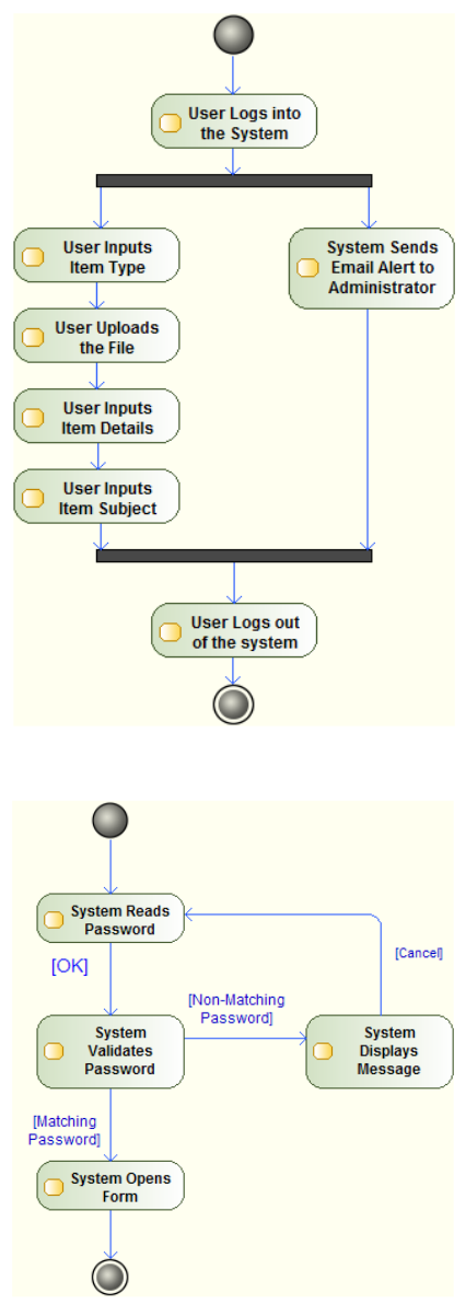
An activity diagram is a state transition diagram that
consists of states and transitions between states as il-
lustrated in Figs. 1-2. A state captures a snapshot
of the system during execution. Each state is given a
name that denotes the current activity captured by the
state. A transition captures the transition of the sys-
tem from one state to another brought about by per-
forming an activity (Jalloul, 2004).
Activity diagrams can capture branching from one
state using two different transitions (see Fig. 1).
Because activity diagrams capture semantics of sce-
narios graphically, these could capture conditionals
and repetition. For example, in Fig. 2, to progress
from the state ‘System Validates Password’ to ‘Sys-
tem Opens Form’, the condition on the transition
Figure 1: UML Activity Diagram resulting from Encode
Item activity.
Figure 2: UML Activity Diagram resulting from User Login
activity.
UML Activity Diagrams for OWL Ontology Building
371
(‘[Matching Password]’) between these two states
should be respected. Otherwise, the condition ‘[Non-
Matching Password]’ is valid, and the next state after
the state ‘System Validates Password’ is the state ‘Sys-
tem Displays Message’.
A constraint is a condition that needs to be satis-
fied for a transition from a state to occur. For example,
in Fig. 2, from the state ‘System Reads Password’ to
the state ‘System Validates Password’, the constraint
on the transition is set as ‘[OK]’.
A looping may be modeled by transitions using
backward arrows from a state to a previous state or
from a state to itself (iteration). For example, in Fig.
2, the transition between the state ‘System Displays
Message’ and the state ‘System Reads Password’ cre-
ates a loop in the process.
Activity diagrams could also model simultaneous
states which are states working simultaneously, i.e.
steps processed in parallel (Ambler, 2005). States
could start simultaneously as graphically notated by a
fork or finish simultaneously as visually symbolized
by a join. For example, in Fig. 1, the states ‘User
Inputs Item Type’ and ‘System Sends Email Alert to
Administrator’ are simultaneous.
On the other hand, an OWL ontology contains
classes, individuals, and properties (Horridge, 2009).
In our approach, activity diagrams contribute to the
process of defining/refining these ontological con-
cepts, since they describe the functionality of the
system as well as its dependencies at a high level
viewpoint. Actions represented in the activity di-
agrams could be translated into ontological proper-
ties and sub-properties. Moreover, activity diagrams
add knowledge about the characteristics of the object
properties set in an ontology. Hence, loops could be
formalized by setting the related properties as transi-
tive and constraints could be formalized by annotating
the resulting properties correspondingly. Thus, the
temporal flow of the activities could be mapped into a
hierarchical structure with defined relation character-
istics as demonstrated in Section 3.
3 EXPERIMENTS AND
DISCUSSION
In order to validate our presented approach, we re-
used the ontology for publications repository In-
formation Management called ePrOnto (Olszewska
et al., 2010), developed with Prot
´
eg
´
e OWL (Prot
´
eg
´
e,
2014) and running on a Windows platform. ePrOnto
is a semi-automatic, single ontology with multiple
layers (different levels of hierarchy). Its domain re-
lies on the ePrints vocabulary (Univerity of Hudders-
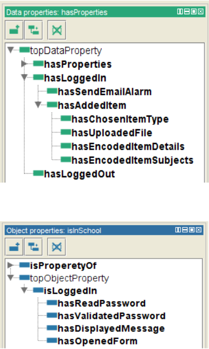
Figure 3: Example of ontological properties mapped from
the Encode Item UML activity diagram.
Figure 4: Example of ontological properties mapped from
the User Login UML activity diagram.
field ePrints, 2014). The key related words have been
identified when logging into ePrints system and do-
ing the task of adding an item (i.e. publication) to the
repository. Capturing this information within a stan-
dard ontology language makes it universally accessi-
ble throughout the Web, and allows it to be analyzed,
queried and compared using powerful, open tools.
While the classes and relations have been de-
fined using techniques presented in (Olszewska et al.,
2014), we refined these properties and relations of the
ontology by extracting and structuring the knowledge
captured in the UML activity diagrams as described
in Section 2.
In the experiments, we have mapped the activ-
ity diagrams presented in Figs. 1-2 into the OWL
ontology. Some of the layers could be seen in Fig.
3 and Fig. 4, respectively. For example, the loop
present in the activity diagram of Fig. 2 between
the actions ‘System Reads Password’, ‘System Vali-
dates Password’, and ‘System Displays Message’ is
KEOD 2015 - 7th International Conference on Knowledge Engineering and Ontology Development
372
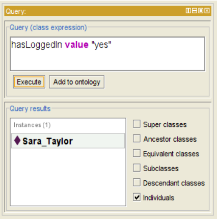
Figure 5: Example of DL query about the action User Lo-
gin.
formalized by setting the related ontological prop-
erties ‘hasReadPassword’, ‘hasValidatedPassword’,
‘hasDisplayedMessage’ (see Fig. 4) as transitive.
The resulting ontology is compatible with the
query process such as illustrated in Fig. 5. In this
case, the system has well detected that the user called
‘Sarah Taylor’ is logged into the system.
From these experiments, we can observe that
UML activity diagrams could refine knowledge about
some processes such as the one presented in Fig. 2.
and create more properties and sub-properties into the
ontology as well as further update information about
the individuals. Thus, UML activity diagrams can be
widely used to design new dynamic ontologies, and
can also be considered as complimentary to dynamic
notations such as BPMN diagrams.
4 CONCLUSIONS
This paper is focused on the design of an ontology
with a dynamic domain. Hence, design notations
such as UML activity diagrams have been used and
translated into OWL in order to systematically model
and/or update ontological concepts and their relations.
The proposed approach has led to the capture of dy-
namic behavior and its transformation into structured
knowledge, leading to the development as well as re-
finement of a complex and large-scale ontology such
as ePronto for the University publication repository
(ePrints) system.
REFERENCES
Ambler, S. (2005). The Elements of UML 2.0 Style. Cam-
bridge University Press, New York, USA.
Baclwaski, K., Kokar, M., Kogut, P., Hart, L., Smith, J.,
Holmes, W., Letkowski, J., and Aronson, M. (2001).
Extending UML to support ontology engneering for
the Semantic Web. In Proceedings of the International
Conference on UML (UML’01).
Bauer, B. and Odell, J. (2005). UML 2.0 and Agents: How
to build agent-based systems with the new UML stan-
dard. Engineering Applications of Artificial Intelli-
gence, 18(2):141–157.
Bernaras, A., Laresgoiti, I., and Corera, J. (1996). Building
and reusing ontologies for electrical network applica-
tions. In Proceedings of the European Conference on
Artificial Intelligence (ECCAI’96), pages 298–302.
Chaware, S. and Rao, S. (2010). Integrated approach to
ontology development methodology with case study.
International Journal of Database Management Sys-
tems, 2:13–19.
Cranefield, S., Haustein, S., and Purvis, M. (2001). UML-
based ontology modelling for software agents. In Pro-
ceedings of the Workshop on Ontologies in Agent Sys-
tems, pages 21–28.
Cranefield, S. and Purvis, M. (1999). UML as an ontol-
ogy modeling language. In Proceedings of the IJCAI
Workshop on Intelligent Information Integration.
De Nicola, A., Missikoff, M., and Navigli, R. (2009). A
software engineering approach to ontology building.
Information Systems, 34(2):258–275.
Fern
´
andez-L
´
opez, M., G
´
omez-P
´
erez, A., and Juristo, N.
(1997). METHONTOLOGY: From ontological art to-
wards ontological engineering. In Proceedings of the
AAAI Spring Symposium Series, pages 33–40.
G
´
omez-P
´
erez, A., Fern
´
andez-L
´
opez, M., and Corcho, O.
(2004). Ontological Engineering. Springer-Verlag,
London.
Gruber, T. (1995). Towards principles for the design of on-
tologies used for knowledge sharing. International
Journal of Human-Computer Studies, 43(5-6):907–
928.
Gruninger, M. and Fox, M. (1995). Methodologies for the
design and evaluation of ontologies. In Proceedings of
the Workshop on Basic Ontological Issues in Knowl-
edge Sharing, pages 6.1–6.10.
Guizzardi, G., Wagner, G., Guarino, N., and van Sinderen,
M. (2004). An ontologically well-founded profile for
UML conceptual models. In Advanced Information
Systems Engineering . Springer Berlin Heidelberg,
pages 112–126.
Horridge, M. (2009). A Practical Guide to Building OWL
Ontologies Using Prot
´
eg
´
e 4 and CO-ODE Tools. Uni-
versity of Manchester, Manchester, UK, 1.2 edition.
Jalloul, G. (2004). UML by Example. Cambridge University
Press, USA, 1st edition.
Kogut, P., Cranefield, S., Hart, L., Dutra, M., Baclawski,
K., Kokar, M., and Smith, J. (2002). UML for on-
tology development. The Knowledge Engineering Re-
view, 17(1):61–64.
UML Activity Diagrams for OWL Ontology Building
373
Lenat, D. and Guha, R. (1990). Building Large Knowledge-
Based Systems: Representation and Inference in the
Cyc Project. Addison-Wesley, Boston, USA.
Lunn, K. (2003). Software Development with UML. Pal-
grave MacMillan, New York, USA.
McCluskey, T. L. and Cresswell, S. N. (2005). Importing
ontological information into planning domain models.
In Proceedings of the ICAPS Workshop on the Role of
Ontologies in Planning and Scheduling. AAAI Press,
pages 5–12.
Ohgren, A. and Sandkuhl, K. (2005). Towards a methodol-
ogy for ontology development in small and medium-
sized enterprises. In Proceedings of the IADIS In-
ternational Conference on Applied Computing, pages
369–376.
Olszewska, J., Simpson, R., and McCluskey, T. (2010).
ePrOnto: OWL-Based Ontology for Research Infor-
mation Management. In JISC Technical Report.
Olszewska, J. I., Simpson, R. M., and McCluskey, T. L.
(2014). Dynamic OWL ontology design using UML
and BPMN. In Proceedings of the INSTICC Inter-
national Conference on Knowledge Engineering and
Ontology Development (KEOD’14), pages 436–444.
Prot
´
eg
´
e (2014). Open-source ontology editor. Software
available online at: http://protege.stanford.edu/.
Swartout, B., Ramesh, P., Knight, K., and Russ, T. (1997).
Towards distributed use of large-scale ontologies. In
Proceedings of the AAAI Symposium on Ontological
on Ontological Engineering, pages 33–40.
Univerity of Huddersfield ePrints (2014). University
of Huddersfield Repository. Available online at:
http://eprints.hud.ac.uk/.
Uschold, M. and Gruninger, M. (1996). Ontologies: Princi-
ples, methods and applications. Knowledge Engineer-
ing Review, 11:1–44.
Uschold, M. and King, M. (1995). Towards a methodology
for building ontologies. In Proceedings of the IJCAI
Workshop on Basic Ontological Issues in Knowledge
Sharing, pages 2–15.
Wang, X. and Chan, C. W. (2001). Ontology model-
ing using UML. In Proceedings of the International
Conference on Object Oriented Information Systems.
Springer London, page 5968.
Wohed, P., van der Aalst, W. M., Dumas, M., ter Hofstede,
A. H., and Russell, N. (2005). Pattern-based analy-
sis of the control-flow perspective of UML activity di-
agrams. In Conceptual ModelingER 2005. Springer
Berlin Heidelberg, pages 63–78.
KEOD 2015 - 7th International Conference on Knowledge Engineering and Ontology Development
374
