Web-enabled Neuron Model Hardware Implementation and Testing
Fearghal Morgan, Finn Krewer, Frank Callaly, Aedan Coffey and Brian Mc Ginley
College of Engineering and Informatics, National University of Ireland, Galway, Ireland
Keywords: Brain-inspired Computation, Biological Neural Networks, FPGA Hardware Neural Networks, Low Entropy
Model Specification (LEMS), VHDL, Web-enabled Neural Capture.
Abstract: This paper presents a prototype web-based Graphical User Interface (GUI) platform for integrating and testing
a system that can perform Low-Entropy Model Specification (LEMS) neural network description to Hardware
Description Language (VHDL) conversion, and automatic synthesis and neuron implementation and testing
on Field Programmable Gate Array (FPGA) testbed hardware. This system enables hardware implementation
of neuron components and their connection in a small neural network testbed. This system incorporates
functionality for automatic LEMS to synthesisable VHDL translation, automatic VHDL integration with
FPGA logic to enable data I/O, automatic FPGA bitfile generation using Xilinx PlanAhead, automated multi-
FPGA testbed configuration, neural network parameter configuration and flexible testing of FPGA based
neuron models. The prototype UI supports clock step control and real-time monitoring of internal signals.
References are provided to video demonstrations.
1 INTRODUCTION
In recent years, spiking Neural Networks (NNs) have
been implemented on a range of hardware platforms
including Field Programmable Analogue Arrays
(FPAAs) (Rocke et al., 2008; Rocke, 2007; Maher et
al. 2006), FPGAs (Cawley et al., 2011; Morgan et al.
2009; Carrillo et al, 2013; Glackin et al. 2005; Pande
et al., 2010) and multi-processor based systems such
as Spinnaker (Khan et al., 2008). However, to date,
many of these hardware systems do not model
biological neurons to a high-degree of accuracy.
The Low Entropy Model Specification (LEMS)
(Cannon et al., 2014) is a language used to
functionally describe neuron models and neural
networks. LEMS is a declarative language which is
accessible to persons not trained in electronic
engineering or computer science. A large library of
complex and diverse LEMS neuron models exists and
forms the basis of the NeuroML2 NN description
language. LEMS descriptions are often exported to
various software simulators such as NEURON and
BRIAN for optimised execution.
The research proposed in this paper captures
biologically realistic neuron models in the LEMS
neuron and neural network modelling language
before translating the models to synthesisable
Hardware Description Language (VHDL) and
implementing the neural network on a testbed
comprised of Field Programmable Gate Arrays
(FPGAs). The work is a contribution to the overall Si
elegans system (Blau et al. 2014).
This paper presents a prototype web-based
Graphical User Interface (GUI) platform for
integrating and testing a system that can perform
LEMS neural network description to VHDL language
conversion, automatic synthesis and neuron
implementation on FPGA hardware, and their
connection in a small neural network. This system
provides a working end-to-end system on which User
Interface (UI) neural networks may be prototyped and
tested in hardware. The system incorporates
automatic LEMS to VHDL translation, automatic
VHDL integration with FPGA logic to enable data
I/O, automatic FPGA bitfile generation using Xilinx
PlanAhead, automated multi-FPGA configuration,
neural parameter configuration and flexible testing of
FPGA based neuron models. The prototype UI
supports clock step control and real-time monitoring
of internal signals. This work is demonstrated at
Morgan et al, 2014.
The structure of this paper is as follows: Section 2
describes the neural network prototype high level
architecture. Section 3 overviews each of the UI
elements. Section 4 describes the Prototype Neuron
Model Capture UI. Section 5 outlines the Experiment
Control UI. Finally, section 6 concludes the paper.
138
Morgan, F., Krewer, F., Callaly, F., Coffey, A. and Ginley, B..
Web-enabled Neuron Model Hardware Implementation and Testing.
In Proceedings of the 3rd International Congress on Neurotechnology, Electronics and Informatics (NEUROTECHNIX 2015), pages 138-145
ISBN: 978-989-758-161-8
Copyright
c
2015 by SCITEPRESS – Science and Technology Publications, Lda. All rights reserved
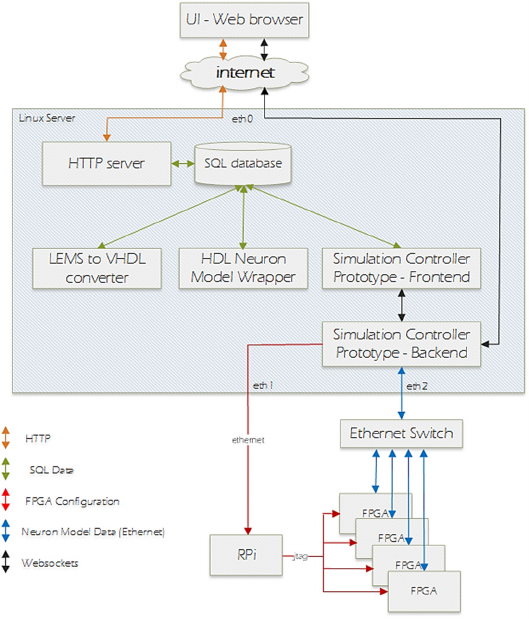
Figure 1: Prototype System Architecture.
2 PROTOTYPE SYSTEM HIGH
LEVEL ARCHITECTURE
This section outlines the high-level structure of the
prototype system (shown in Fig 1). An example user
usage scenario sequence for the prototype is as
follows:
1. Define neuron model in LEMS.
2. Upload model to the application server through a
web browser.
3. Define neuron model test through the web UI.
4. Request test execution on FPGA hardware.
5. View neuron model behaviour in the browser as
the test is running.
The current implementation of the prototype system
facilitates a single biologically plausible neuron
model to be used in each of 8 FPGAs to provide a
hardware neural network simulation. The system is
designed with the intention of future extension to
allow different neuron models to be used during a
simulation.
All user interaction with the system is through a web
browser running on the user’s local machine and
connecting to the prototype system over the internet.
All server-side software components are deployed on
a single server machine running the Ubuntu Linux
operating system. The server has three active Ethernet
interfaces, namely:
1. eth0 - server to internet.
2. eth1 - server to a Raspberry Pi (RPi) which
facilitates testbed FPGA configuration using
JTAG (Joint Test Action Group).
3. eth2 - server to Ethernet switch to which all
FPGAs are also connected. This third network
interface is used for all data transmission to/from
neuron models running on the FPGAs.
The following technologies are used in the prototype
system:
• All user interface elements are implemented in
HTML5, CSS and Javascript.
• Server-side web application processing uses the
Django web application framework for the Python
programming language.
• Data storage uses an sqlite database.
• The LEMS to VHDL converter (Krewer et al.,
2014) is implemented in Java with a thin Python
frontend. Communication between the Java and
Python components is over XML-RPC.
• The Java component of the LEMS to VHDL
Web-enabled Neuron Model Hardware Implementation and Testing
139
converter is implemented as a Java servlet
deployed in the Apache Tomcat container.
• The VHDL neuron model wrapper framework is
implemented as an XML-RPC service with a thin
frontend that provides database communications.
• The simulation controller prototype is
implemented as a service with a thin frontend that
provides database communications. Communi-
cation between the backend and frontend of the
simulation controller prototype uses the
websocket protocol.
• The websocket interface to the simulation
controller prototype backend is also used to allow
a web-browser to connect directly to the backend
of the simulation controller to retrieve real-time
data from an ongoing simulation.
• The server-side websocket interface uses the
Tornado framework for Python.
• The FPGAs used are Xilinx Spartan 6 FPGAs on
Digilent Nexys 3 development boards.
• Testbed FPGA configuration is performed
through a Raspberry Pi single board computer
with a JTAG connection to all FPGAs. The
Raspberry Pi uses the UrJTAG library to perform
FPGA configuration over JTAG.
The UI allows the user to add neuron models to the
model library, edit existing models, define FPGA
simulations, and configure and run simulations on
FPGA hardware. The elements of the UI are
described in section 3.
In response to user activity in the UI, the system
completes a selection of the following steps:
• LEMS neuron model to VHDL conversion and
model verification.
• Synthesis, FPGA place and route and generation
of FPGA configuration bitstream files, using
Xilinx Electronic Design Automation tools.
• Configuration of multi-FPGA hardware testbed
• Simulation using FPGA hardware.
The LEMS to VHDL converter (see Fig 1) monitors
the database for models that have been added in
LEMS format but have not yet been converted to
VHDL. On finding these models, the system extracts
the LEMS data and converts the model to VHDL.
3 USER INTERFACE ELEMENTS
The prototype system implements a web UI which
allows users to add neuron models to the system in
LEMS format. When a new model is uploaded or an
existing model is changed, the system automatically
builds an FPGA bitfile for the model. The system
allows users to define simulations which use the
uploaded models (as described in Section 4).
Simulations may be defined as a set of instructions
which may include Python-style control elements.
Simulations may also be defined graphically through
a simulation definition user interface. The simulation
definition UI (described in Section 5) provides the
following functionality:
• Users may specify the number of neurons they
would like in their simulation neural network.
• Users can set parameter values for each neuron in
the simulation.
• Users can specify which variables from each
neuron they would like recorded.
• Users can define stimulus spikes to be injected
into the NN. These spikes are sent from the server
into the FPGA NN during the simulation.
• Users can specify the number of neural network
timesteps that they would like the simulation to
run for.
4 PROTOTYPE NEURON MODEL
CAPTURE UI
The UI for uploading and managing neuron models
primarily consists of two screens, namely the Neuron
Model List UI and the Neuron Model Edit UI.
4.1 Neuron Model List UI
Neuron Model List UI, illustrated in Fig 2, shows a
list of all neuron models available to a user. An
uploaded neuron model is automatically processed by
the LEMS->VHDL->bitfile pipeline. The status field
in the model gives the user an indication of what stage
in the pipeline a model is currently at.
The LEMS column in the model list indicates
whether this model was uploaded as a LEMS model.
If this is set to ‘Yes’ then the word ‘Yes’ is a
hyperlink that lets a user download the original
LEMS data.
The VHDL column in the model list indicates
whether a VHDL version of this model is available on
the system. If this is set to ‘Yes’ then the word ‘Yes’
is a hyperlink that lets a user download a zip archive
containing the VHDL files for the model. A VHDL
version of the model is available if the model was
uploaded in LEMS format and the LEMS to VHDL
conversion has completed successfully.
The bitfile column in the model list indicates whether
an FPGA configuration bitfile is available on the
system for this model. A bitfile will be available for a
model if the FPGA synthesis has completed
successfully. If this field is set to ‘Yes’ then the model
status will be ‘READY’.
NeBICA 2015 - Symposium on Neuro-Bio-Inspired Computation and Architectures
140
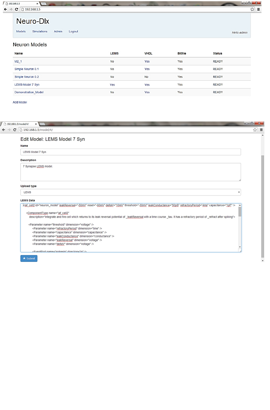
Figure 2: Neuron Model List UI.
Figure 3: Neuron Model Edit UI - LEMS Model.
The Model status field may be one of the following:
• RAW: Model has just been uploaded in LEMS
though is not yet processed by the system.
A model in this state has been queued for
processing by the LEMS to VHDL converter.
• CONVERTING: Model is currently being
processed by the LEMS to VHDL converter.
• CONVERT FAILED: LEMS to VHDL process
has failed. Detailed information about the cause of
the failure is stored in the database and is available
through the Admin interface.
• CONVERTED: VHDL for this model is available
on the system. A model in this state has been
queued for processing by the synthesis tool.
• WRAPPING: VHDL for the model is currently
being synthesised.
WRAPPING FAILED: VHDL Neuron Model
synthesis failed to synthesise the model. Detailed
information about the cause of the failure is stored
in the database and is available through the Admin
interface.
• READY: VHDL Neuron Model synthesis has
successfully processed the model and a bitfile is
now available for this model. This model may
now be used in the simulation definition UI.
4.2 Neuron Model Edit UI
A user may add a new model to the system or edit an
Web-enabled Neuron Model Hardware Implementation and Testing
141
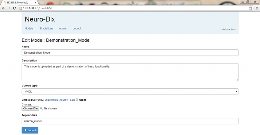
Figure 4: Neuron Model Edit UI - VHDL Model.
existing model through the Model Edit UI (Figs 3 and
4). The user can access this UI through the Neuron
Model List UI by clicking on a model name to edit an
existing model or by clicking the ‘Add Model’ link to
create a new model. If users wants to upload a LEMS
model, they will be prompted to enter the LEMS
description of the model into a resizable text area.
5 SIMULATION CONTROL UI
A simulation definition is a list of instructions that are
interpreted by the simulation controller prototype (see
Fig 1). These instructions can trigger the simulation
controller to load a particular bitfile onto the specified
FPGAs, to read and write to neuron model signals to
inject neural spikes into the network of FPGAs and to
increment the simulation time on the FPGAs.
The UI screens in this section allow users to create
and execute a simulation definition. This is done
through the following UI screens:
• Simulation definition and instance list screen (Fig 5).
• Raw simulation definition screen (Fig 6).
• Graphical simulation definition screen (Fig 7) .
Two methods are provided for defining a simulation.
• The raw simulation definition screen (Fig 6)
provides a low-level mechanism for maximum
flexibility in defining a simulation. This is
primarily intended for system testing and
debugging. This method requires the user to have
some understanding of the workings of the
system.
• The graphical simulation definition screen (Fig 7)
provides a high-level mechanism that requires no
prior knowledge of the workings of the system.
5.1 Simulation Definition
The Simulation Definition and Instance List UI
screen is shown in Fig 5. This screen displays a list of
simulation definitions available to the user. Each has
previously been defined either in the raw simulation
definition screen (Fig 6) or the graphical simulation
definition screen (Fig 7). When a simulation
definition has been added by a user, they can then
choose to either:
• Schedule the simulation to be run: this option is
selected by clicking the ‘Schedule Run’ link
beside the simulation definition. This queues the
simulation for running when the FPGA hardware
is next available. The results of the simulation are
added to the database when the simulation is
complete.
• Run the simulation immediately: this option is
selected by clicking the ‘Run Live’ link beside the
simulation definition. This option requests that the
simulation be run immediately on the FPGA
hardware. If another simulation is currently
running then the request is denied and a message
is displayed to the user in the web UI indicating
that the FPGA hardware is currently busy. If the
FPGA hardware is free then the simulation is
passed to the simulation controller and the
simulation results data is stored in the database
for later review.
NeBICA 2015 - Symposium on Neuro-Bio-Inspired Computation and Architectures
142
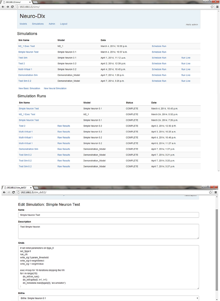
Figure 5: Simulation Definitions and Instances List UI.
Figure 6: Raw Simulation Definition UI.
If a simulation has been scheduled for running then
an instance of that simulation is added to the
simulation instances list. This list is displayed
underneath the simulation definitions list (Fig 5). The
status column is initially ‘SCHEDULED’. When a
simulation is running on the FPGA hardware its status
field is set to ‘RUNNING’. When a simulation has
finished its status field is set to ‘COMPLETE’.
5.2 Raw Simulation Definition
The Raw Simulation Definition UI screen is shown
Web-enabled Neuron Model Hardware Implementation and Testing
143
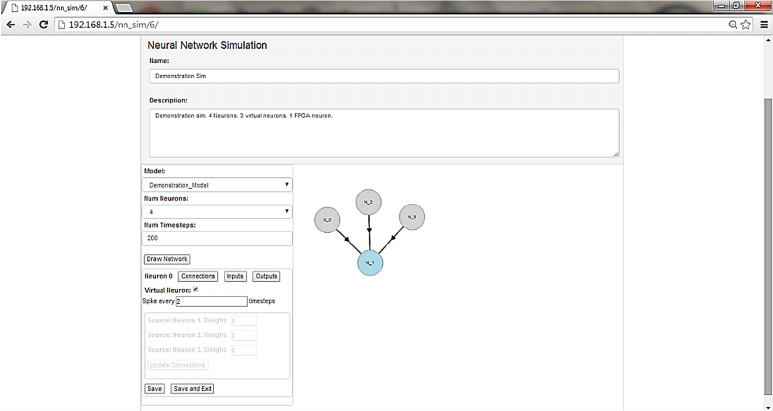
Figure 7: Graphical Simulation Definition UI.
in Fig 6. This screen allows a user to define a
simulation as a list of instructions to be sent to the
simulation controller prototype (see Fig 1). This
instruction set allows users to select specific FPGAs
for configuration, read from specific neuron model
variables on each FPGA, write to configure model
parameters on each FPGA, inject spike stimulus
patterns into the hardware neural network (to mimic
sensory input), and increment the neural network time
(by progressing by a time step).
5.3 Graphical Simulation Definition
The Graphical Simulation Definition UI screen is
shown in Fig 7. This screen allows a user to define a
simulation through the UI without knowledge of the
underlying instructions that are to be passed to the
simulation controller to execute the simulation.
Simulations defined through the Raw Simulation
Definition UI and the Graphical Simulation
Definition UI have the same functionality available to
them.
In this UI the user typically first adds a simulation
name and description, and then selects the neuron
model to be used in the simulation from the dropdown
box of neuron models. The user then specifies the
number of neurons to be used in the simulation and
clicks the ‘Draw Network’ button. This results in a
graphical representation of the requested number of
neurons on the right-hand side panel (Fig 7). The user
can drag these neurons within the panel to clearly
visualise the network used in the simulation.
The parameters from the neuron model that define
the synaptic weights are identified by the UI through
a naming convention shared between the LEMS to
VHDL converter and the UI. The user can set the
value to be used for any neuron parameter in any
specific neuron by clicking on the neuron in the right-
hand side visualisation window and then clicking the
‘Inputs’ button in the left-hand panel.
Any neuron can be marked as being a ‘Virtual
Neuron’ by selecting the neuron in the right-hand
window and then checking the ‘virtual neuron’
checkbox in the left-hand window. This is a
mechanism to allow spikes to be injected into the
neural network from the server as if they were coming
from a number of different neurons. Virtual neurons
model neuron behaviour only in so far as they
generate programmed patterns of spikes, which are
injected into the neural network by the Simulation
Controller during the simulation. The user can specify
the rate at which spikes are injected into the FPGA
neural network from virtual neurons during the
simulation. Spike rates are defined in terms of
simulation timesteps.
6 CONCLUSIONS
This paper has presented a prototype web-based GUI
platform for integrating and testing a system that can
perform Low-Entropy Model Specification (LEMS)
neural network description to VHDL language
conversion, automatic synthesis and neural network
implementation on FPGA hardware. This system
provides a working end-to-end system on which UI
components may be prototyped and tested, and
captured neural networks may be implemented in
hardware. The prototype UI supports clock step
NeBICA 2015 - Symposium on Neuro-Bio-Inspired Computation and Architectures
144
control and real-time monitoring of internal signals.
This work is demonstrated at (Morgan et al, 2014).
ACKNOWLEDGEMENTS
This work has been completed as part of the Si
elegans project funded under FP7 FET initiative
NBIS (ICT-2011.9.11). This work is also supported
by the Irish Research Council.
REFERENCES
Blau, A., Callaly, F., Cawley, S., Coffey, A., De Mauro, A.,
Epelde, G. & Wade, J. (2014, October). Exploring
neural principles with Si elegans, a neuromimetic
representation of the nematode Caenorhabditis elegans.
In Proceedings of the 2nd International Congress on
Neurotechnology, Electronics and Informatics
(NEUROTECHNIX) (pp. 189-194).
Cannon, R. C., Gleeson, P., Crook, S., Ganapathy, G.,
Marin, B., Piasini, E., & Silver, R. A. (2014). LEMS: a
language for expressing complex biological models in
concise and hierarchical form and its use in
underpinning NeuroML 2. Frontiers in
neuroinformatics, 8.
Carrillo, S., Harkin, J., McDaid, L. J., Morgan, F., Pande,
S., Cawley, S., & McGinley, B. (2013). Scalable
hierarchical network-on-chip architecture for spiking
neural network hardware implementations. Parallel and
Distributed Systems, IEEE Transactions on, 24(12),
2451-2461.
Cawley, S., Morgan, F., McGinley, B., Pande, S., McDaid,
L., Carrillo, S., & Harkin, J. (2011). Hardware spiking
neural network prototyping and application. Genetic
Programming and Evolvable Machines, 12(3), 257-
280.
Glackin, B., McGinnity, T. M., Maguire, L. P., Wu, Q. X.,
& Belatreche, A. (2005). A novel approach for the
implementation of large scale spiking neural networks
on FPGA hardware. In Computational Intelligence and
Bioinspired Systems (pp. 552-563). Springer Berlin.
Khan, M. M., Lester, D. R., Plana, L. A., Rast, A., Jin, X.,
Painkras, E., & Furber, S. B. (2008, June). SpiNNaker:
mapping neural networks onto a massively-parallel
chip multiprocessor. In Neural N, 2008. (IEEE World
Congress on Computational Intelligence). IEEE
International Joint Conference on (pp. 2849-2856).
Krewer F., Coffey A., Callaly F. and Morgan F. (2014).
Neuron Models in FPGA Hardware - A Route from
High Level Descriptions to Hardware Implementations.
In Proceedings of the 2nd International Congress on
Neurotechnology, Electronics and Informatics, (pp
177-183)
Maher, J., Ginley, B. M., Rocke, P., & Morgan, F. (2006,
April). Intrinsic hardware evolution of neural networks
in reconfigurable analogue and digital devices. In Field-
Programmable Custom Computing Machines, 2006.
FCCM'06. 14th Annual IEEE Symposium on (pp. 321-
322). IEEE.
Morgan, F., Cawley, S., McGinley, B., Pande, S., McDaid,
L. J., Glackin, B., Maher, J. & Harkin, J. (2009,
December). Exploring the evolution of NoC-based
spiking neural networks on FPGAs. In Field-
Programmable Technology, 2009. FPT 2009.
International Conference on (pp. 300-303). IEEE.
Morgan, F. et al., FPGA NN Prototype Demonstrator
Videos. http://tiny.cc/SielegansD51, 2014
Pande, S., Morgan, F., McCawley, S., Ginley, B., Carrillo,
S., Harkin, J., & McDaid, L. (2010, September).
EMBRACE-SysC for analysis of NoC-based spiking
neural network architectures. In International
Symposium on System-on-Chip. IEEE.
Rocke, P., McGinley, B., Maher, J., Morgan, F., & Harkin,
J. (2008). Investigating the suitability of FPAAs for
evolved hardware spiking neural networks. In
Evolvable Systems: From Biology to Hardware (pp.
118-129). Springer Berlin Heidelberg.
Rocke, P., McGinley, B., Morgan, F., & Maher, J. (2007).
Reconfigurable hardware evolution platform for a
spiking neural network robotics controller. In
Reconfigurable computing: Architectures, tools and
applications (pp. 373-378). Springer Berlin Heidelberg.
Web-enabled Neuron Model Hardware Implementation and Testing
145
