
Computer-aided Design of Transmission Shaft and Rolling Contact
Bearing Selection based on Expert System
Huang Pinghua and Guo Xiaoxi
92941 Unit, huludao,Liaoning,China
14692423@sohu,lasti@qq.com
Keywords: Transmission Shaft Design, Computer-aided Analysis, Expert System, Optimal Selection.
Abstract: In order to solve the inefficiency problem in traditional method of transmission shaft design, this paper
analyzes the strength and deformation of rotation step shaft through computer program. These bearings have
a large number of transmission elements, such as: gear, pulley, etc. Three dimensional modeling is applied
to all of them. Moreover, a motion analysis can be made by detecting the force implemented on the
transmission shaft. The finite element method is applied to calculate V shaped groove of stress
concentration which is presented in a diagram, and finally, the optimal rolling contact bearing is selected
based on the knowledge of expert system.
1 INTRODUCTION
To adopt the traditional method to design and
analyze machine parts is a quite troublesome job.
Recently, computer-aided design and analysis is
introduced into this field. Therein, the transmission
shaft is used to transmit force and motion, the
corresponding design requires a large number of
calculation and diagrams. The method of
computer-aided modeling can be used to effectively
design the transmission shaft and reduce plentiful of
work amount. The software adopted in
computer-aided design can be independently
developed or resorted to the existing commercial
software.
The force-transmit element on the transmission
shaft must be accurately positioned. It is advised to
use the shaft shoulder of step shaft to make sure that
these elements are aligned to the coordinate of the
shaft and assembled. Besides, the stress analysis for
special points on the shaft must also be taken into
consideration.
This paper studies the computer-aided analysis
of transmission shaft under two dimension
conditions and supposes that the force-transmit
element be able to bear imaginable force. The more
the elements on the shaft are, the more complicated
the analysis will be. If the influence of stress
concentration is taken into consideration, plus
application of the traditional solution, the calculation
will be very time-consuming and complicated.
Furthermore, stress concentration data presented in
diagrams is inconvenient for reading. The purpose
of this paper is to analyze and select the optimal
diameter of shaft, so as to make it strong and rigid
enough to satisfy the stipulated conditions. The
computer program is applied to obtain the optimal
parameters for critical section and the stress
concentration data is formulized and adjusted to
adapt to the needs for being entered into computer.
Based on the aforesaid calculation, under provided
assembling condition of the shaft, the optimal
rolling contact bearing can be selected. The
realization of the aforesaid function cannot occur
without the assistance of expert system. It can serve
3
Pinghua H. and Xiaoxi G.
Computer-aided Design of Transmission Shaft and Rolling Contact Bearing Selection based on Expert System.
DOI: 10.5220/0006018000030006
In Proceedings of the Information Science and Management Engineering III (ISME 2015), pages 3-6
ISBN: 978-989-758-163-2
Copyright
c
2015 by SCITEPRESS – Science and Technology Publications, Lda. All rights reserved
3
the specific application of selecting materials for the
cutter and designing the cutter. Please consult the
relevant literature for specific details.
2 STEP SHAFT DESIGN
This paper studies the two aspects of shaft design,
i.e., deflection and rigidity, pressure and strength.
Deflection and rigidity covers the two kinds of
motions of bending and twisting, deflection and the
inclination of force bearing point. Pressure and
strength involves fatigue strength and stability. The
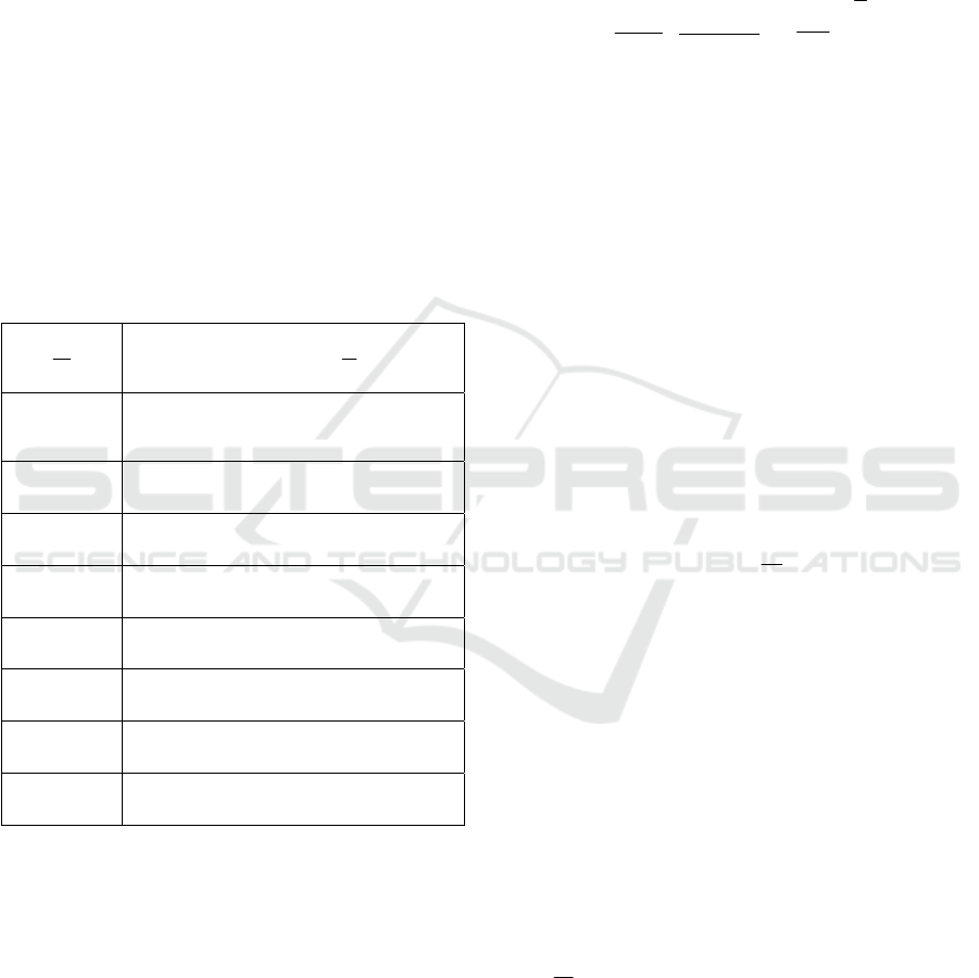
theoretic data is shown in Table I:
Table 1:Theoretic data of bending shaft
K
T
.
d
D
K
T
【Note: A=(
d
r
)】
1.01
0.9034×
A
18.0−
1.02
0.938×
A
19.0−
1.03
0.95
A
2.0−
1.05
0.956×
A
21.0−
1.1
0.9496×
A
23.0−
1.2
0.926×
A
25.0−
1.5
0.916×
A
27.0−
2
0.896×
A
3.0−
2.1 Influencing Factors and Linear
Regression
When the shaft bears completely reverse bending
force and stable torque, the critical bending stress
generally lies in the stress concentration point.
Stress concentration generally occurs within limited
range where geometric shapes are not continuous,
for example, the v-shaped groove. At the time of
designing the equation, the influence from stress
concentration must be taken into account. With
various factors having been taken into consideration,
the calculation formula for shaft diameter is as
follows:
()
[
]
{
}
S
ut
T
m
S
e
M
a
K
f
n
d
2
2
32
3
1
+
∗
∗
=
π
(1)
Where,
M
a
is bending moment,
T
m
is torque, n
is safety coefficient,
S
ut
is the ultimate strength
of material. .
′
∗∗=
S
K
K
K
S
e
dcb
e
,
(
)
11 −+=
KK
Tf
q is
fatigue stress concentration factor.
K
K
K
dcb
,,
respectively represent dimension, groove and
surface factor.
q
is the V-shaped groove sensitive
factor. The calculation formula for
K
T
is as
follows:
1
6
1
i
TTi
r
KK
d
−
=
⎛⎞
∑
⎜⎟
⎝⎠
(2)
where,
d
D
B
B
B
B
B
B
B
BK
BK
BK
BK
BK
BK
T
T
T
T
T
T
=
−−−=
++=
+−=
−+−=
+−=
−+−=
.7.8575.5154161
,86167.44.29197.1946
,15.462249566.416
,8.21715.8674.399
,022.418.145932.86
,43687.3681.1172706.6
2
6
2
5
2
4
2
3
2
2
2
1
2.2 Deflection Analysis
Deflection analysis cannot be started unless the
geometric shape of the shaft is completely
ISME 2015 - Information Science and Management Engineering III
4
ISME 2015 - International Conference on Information System and Management Engineering
4

determined. It is one function for complete
geometric shape of the shaft. Meanwhile, the
pressure of the point we are studying is the function
for the deformation and motion of this point.
Therefore, in case of designing and analyzing step
shaft, pressure and strength calculation must be
taken into consideration. In the meanwhile of
determining the deflection, the dimension of the
shaft must be given. The mixed torque borne by step
shaft comes from the axial force of spiral and helical
gears. Therefore, deflection calculation adopts
elastic limit rather than curvature radius
ρ
. The
calculation formula for curvature radius
ρ
:
[]
dx
dy
x
d
y
d
2
1
2
3
2
2
1
+
±=
ρ
(4)
The calculation formula for shaft camber y can be
obtained by using finite element method.
()
M
i
M
i
M
i
EI
h
y
i
y
i
y
i
y
i
1
2
1
2
2
1
5
4
23
+
+−
−
=+
+
−
+
+
+
−
(5)
h is pitch, E is elastic limit, M is bending moment
and I is moment of inertia.
3 COMPUTER PROGRAM
DEVELOPMENT
This program is developed based on Q-Basic
language. It is simple and easy to operate. It is
applicable for personal computer. Moreover, this
program is provided with such functions as digital
analysis, vector calculation and graphic description.
It enables the users to solve their unique problems.
Besides, it is provided with interactive function and
a basic database with detailed instructions on
different materials attached thereto.
The calculation content includes the base
reaction force from two directions of vertical and
horizontal, bending moment diagram, deflection and
shaft inclination. Then, based on the aforesaid
calculation, the optimal rolling contact bearing is
selected. To conduct shaft analysis, firstly, it is
required to choose the appropriate material and
design parameters, for instance: the position of
rolling contact bearing and machine parts, rotating
direction and the designed length of shaft. Similarly,
to conduct strength calculation, it is required to
choose safety coefficient, input force and rounds per
minute. The calculation of force and torque of gears
on the shaft is decided by the corresponding
parameters entered in, for instance, pitch, etc. The
bending moment is calculated in digital mode,
including the two directions of horizontal and
vertical. Then, it goes through smoothing processing
and is presented in diagrams. The calculation of the
parameter of critical point and force and torque
under the condition of composite loads can be
processed simultaneously. At the time of calculating
bending deflection, the two directions of vertical and
horizontal should be taken into account. With the
aforesaid calculation result, the optimal diameter of
step shaft can be obtained by using the two methods
of one-dimension search and interval halving. See
computer program for specific realization.
4 ROLLING CONTACT SHAFT
SELECTION and DATABASE
DEVELOPMENT
Due to the needs of function, the rolling contact
bearing is required to have reasonable service life,
high stability and rather low cost. To reach the
aforesaid requirements, the dynamic bearing
capacity, working conditions, equal bearing capacity
and constant load and so on must be taken into
account. The calculation formula for equal bearing
capacity.
Computer-aided Design of Transmission Shaft and Rolling Contact Bearing Selection based on Expert System
5
Computer-aided Design of Transmission Shaft and Rolling Contact Bearing Selection based on Expert System
5
(
F
eqv
):
F
eqv
F
F
ar
YX +∗=
(6)
where,
F
r
is axial force,
F
a
is radial force. The
calculation formula for dynamic bearing capacity:
(
)
10
6
L
K
F
eqv
C =
(7)
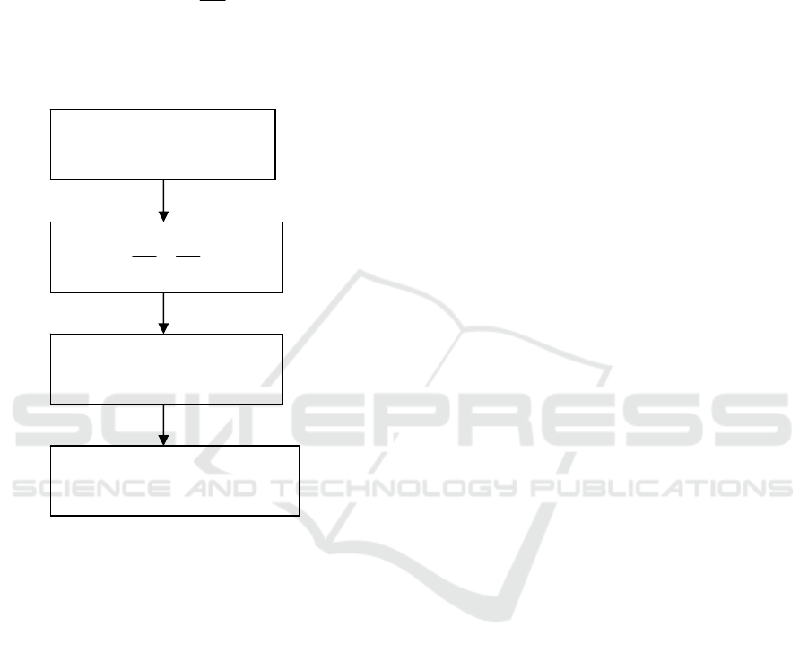
the specific selection process is seen in the flow
chart below.
Flow Chart 1
Expert system is a computer simulation program
based on knowledge. It adopts knowledge-decision
unit and IF_THEN rule to conduct reasoning. The
expert system mainly comprises several parts like
database, decision unit, and storage unit, etc. To
apply this expert system, one must use LEONARDO
software.
5 CONCLUSION
a. The computer program developed is considerably
flexible. It allows the users to solve their own
specific problems. The fatigue analysis for optimal
shaft design and stress sensitive factor are
formulized and entered into computer program.
b. A better protocol is found between calculation of
the optimal diameter of the critical section of step
shaft by using computer simulation method and
analytic method. Moreover, a balance is also
reached between value calculation method and
analytic method in terms of bending-torsion and
torque.
c. The expert system adopting the optimal rolling
contact bearing is developed. It can be used for the
teaching of computer-aided design.
REFERENCES
PU Liang-gui, JI Ming-gang, 2001. Machine Design
HIGER EDUCATION PRESS. Beijing.
YING Hui, 2001. Discussion on the design of recycled
water supply systems for rare metals metallurgical
Plant. Rare Metals and Cemented
Carbides,03:50-52,55.
ZHANG Yu-dong, WU Le-nan, WANG Shui-hua, 2010.
Survey the development rule of Expert system.
Computer Engineering and Applications,19:43-47.
XU Tong-le, CHEN Wu-qin, 2010. Research of rolling
bearing fault diagnosis based on expert system. Coal
Mine Machinery, 11:234-236.
CAI-fan, LI Chu-ye, MA Yan, 2010. Contact pressure and
pull-out force reffect on the interference fit.Machinery
Design&Manufacture, 11:7-9.
LI Wei, LI Wen-bin,2014. Analysis and Design of Shaft
System Structure of Separated High-speed
Rolling
Structure. Machine Building& Automation
,2014,
43( 2) : 19- 23
TANG Lin, ZOU Hui-jun, 2000. Accomplishing CAD of
mechanical kinematic scheme by the design unit
approach, Journal of Computer-Aided Design &
Computer Graphics, 8:614-617.
d
RRRR
BZBYAZAY
,,,,
F
r
F
a
e
C
F
a
,,
C
F
eqv
,
Compare C and the preset value
and choose the optimal one
ISME 2015 - Information Science and Management Engineering III
6
ISME 2015 - International Conference on Information System and Management Engineering
6
