
Cause Analysis and Treatment of Abnormal Shear in Head Cutting
Flying Shear of Hot Rolling
Xiaoyan Chen
Department of Telecommunication Engineering, Hubei Radio & TV University, WuHan,, China
147897514@qq.com
Keywords: The Flying Shear Control, Abnormal Cut, Optimal Signal Switching.
Abstract: Precise shearing of flying shear plays a very important role in cost control of a hot-roll line. The
malfunction of sensors which help to locate where to cut accurately makes it difficult to achieve this goal.
This paper discussed in detail three key control processes in completing precise shearing. Possible causes of
abnormal shear in production practice were analyzed, based on which the optimal signal switching control
measures was put forwards. A monitoring system watchdoged the signals from sensor. If sampling showed
that malfunction happened, a backup signal was used. Also the possible backup signals were discussed how
to replace the breakdown devices. In practice, these measures obtain a good application effect in precise
shearing. Mistakes in cutting are reduced to minimum.
1 INTRODUCTION
Flying shear is one of key equipments in hot rolling
line, used to cut the lower temperature and irregular
parts in strip ends after rough rolling. This procedure
can prevent band steel from jamming in finish
rolling process and reduce the impact on the mill
rolls from the irregular part. Precise shearing can
also help achieve effective improvement in the
production.
Abnormal cut happens frequently in the head/tail
cutting and cutting waste loss accounts for more
than 1.5% loss of the whole process. When the head
/ tail enters the finishing mill, it is very easy to cause
the serious accident of roll breakage. If abnormal
shear frequency can reduce by 50%, loss will be
lowered by 3%, and direct economic benefits of
more than 6000000 RMB Yuan can be achieved.
2 THREE CRITICAL CONTROLS
OF FLYING SHEAR PROCESS
A complete precise shear process can be gained by
controlling flying shear to complete the following
three key functions (OUYANG Xiang-xin, 2003):
strip end tracking and calculation, strip speed
tracking and control and shear blade position
tracking and control (Masahiro Kayama etc, 1998).
2.1 Strip End Tracking / Calculation
As the basis of flying shear accurate cutting control,
motion control unit must accurately track and
compute the strip end position, in order to determine
when the shear performing certain actions. It makes
possible that the blade cuts into the strip at set length
(distance to the strip ends) and moves with the bar
until the strip is cut off (Jiro Jumayama etc,1996).
2.2 Tracking / Control Strip Speed
In order to ensure cutting blade touching the strip at
right time, the component of velocity along the
rolling direction must be kept consistent with that of
the strip until the strip is cut, which requires the
exact tracking and control of strip speed based on
the strip end tracking and calculation. Drum flying
shear with a crank is employed in this plant. The
structure is shown in Figure 1. Space trajectory of
shear blade in the cutting process is round, as shown
in figure 2.
393
Chen X.
Cause Analysis and Treatment of Abnormal Shear in Head Cutting Flying Shear of Hot Rolling.
DOI: 10.5220/0006027103930396
In Proceedings of the Information Science and Management Engineering III (ISME 2015), pages 393-396
ISBN: 978-989-758-163-2
Copyright
c
2015 by SCITEPRESS – Science and Technology Publications, Lda. All rights reserved
393

Figure 1: Sketch map of flying shear.
.
Figure 2: Trajectory of shear blade.
Velocity tracking is shown in equation:
Vc = K(2Lc - LR2+ r*sinα)/ 2Lc *
VL/cosα
(1)
Vc - set velocity of shear, m/s,
K - leading or lag coefficient,
r - trajectory radius of shear blade, mm,
α - cutting angle calculated from the thickness of
steel, °
Lc -circumference distance of blade in this stage,
mm,
LR2 - distance between cutting point and flying
shear, mm.
According to the position relationship between the
cutting blade and strip, blade track is divided into
four stages.
POS1: from Start position to AX in figure 3. The
primary control target is to control cutting
blade location based on the strip end position,
which determines the accuracy of cutting
length. At the same time, the control system
requirements horizontal velocity of cutting
blade at the end of the stage (AX) and the
value is equal to that of strip , so the velocity
control target has to be achieved - setting
target speed according to the end position of
band.
POS2: from AX to the 00 position in the figure 3.
Because the blade has touched the strip, the
actual cutting length is fixed, therefore in this
stage the only control objective is to cut at the
same speed with the strip.
POS3: from figure 00 positions to AY. In the same
stage although blade has cut the strip, the
blade is still with the strip. Therefore, the
control goal is to follow the speed of the
band.
POS4: from AY to Start position. The stage is a
slow-down process, so position control is the
only goal, which makes the blade stop in the
starting position.
2.3 Tracking / Control Strip Speed
The following is formula of the position control:
P = 270°- (2Lc - LR2 + r* sinα) *( 270°–α)/ 2Lc (2)
P-set position of blade
In POS1, position control can compensate for the
shearing speed changes in following the actual speed
of strip when the final position is unpredictable. So
both speed control and position control is important
in this stage. So blade cuts into bar steel at
synchronous speed (horizontal) of strip in set cutting
position, ensuring the flying shear can coherently
finish cutting process even in velocity fluctuations.
In POS2 and POS3, position controller
implements cutting, and there is only speed control
to the blade.
In POS4, as mentioned before, there is only
position control to the blade. So the output of the
speed controller is always zero. Setting value is 270.
The system diagram is as shown in Fig.3.
Figure 3: System diagram of shear control.
ISME 2015 - Information Science and Management Engineering III
394
ISME 2015 - International Conference on Information System and Management Engineering
394
3 ANALYSIS ON THE CAUSES
OF TYPICAL ABNORMAL
SHEAR
In practice, because of the influence of the cooling
water, rolling vibration and electromagnetic
interference, abnormal shear occurs mostly when the
bar end calculation is not accurate caused by the
abnormal signal gotten from the line.
3.1 Laser Velometer Measurement
Abnormal
Due to poor field conditions and effect of water fog,
or the velocimeter's own fault, signal is abnormal, as
shown in Fig. 4.This situation mostly leads to
missing cutting the head of the band.
Figure 4: Abnormal signal from Laser velocimeter.
Signal from laser velocimeter for the strip speed
in the shear region is a constant value. But
sometimes the value suddenly drops to zero.
3.2 Measure Roll Tacho Measurement
Abnormal
The feedback value waveform coming from feed
roller encoder after clamping roller, which is used to
strip tail length calculation and velocity tracking
concusses, indicates the fluctuation of velocity.
Waveform deterioration leads to inaccurate tail
length calculation and tail cutting normal. The
abnormal situation is shown in figure 5.
Figure 5: Abnormal signal from Measure roll tacho.
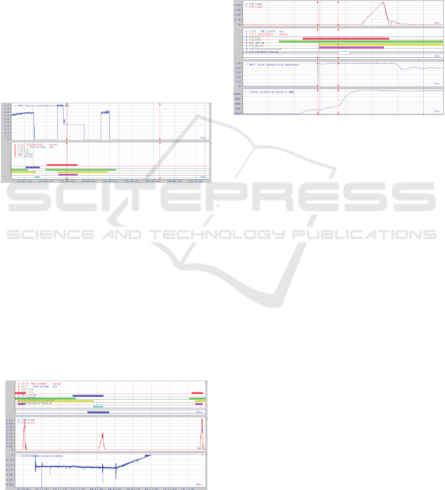
3.3 HMD FZ2 Measurement Abnormal
As is shown in Figure 6, the FZ2 and laser
velocimeter is turned on at almost the same time,
then turned off immediately. This is a early missing
connection, leading to the subsequent flying shear
early cutting. In the end, the blade misses cutting the
head of band, because of the arrival of thermal field
ahead of the actual situation.
Figure 6: Abnormal signal from FZ2.
4 MEASURES
Abnormal shear is caused by the abnormalities of
measurement in the field. In order to improve the
cutting precision, a more reliable substitute signals
must be found as a standby signal. When the main
signals are abnormal, fast switching will use standby
signal. According to this idea, the following
measures are taken.
4.1 Measures 1: Switch the Abnormal
Signal to Roller Speed from the
Laser Velocimeter, When Cutting
Head
A laser velocimeter is used to measure the actual
speed of the strip in cutting head. Practice has
proved, without considering the slip, speed signal
from roller can be used to substitute the signal from
velocimeter. By using logic judgment between laser
velocimetry and roller speed, the abnormal signal
from laser velocimeter can automatically switch to
that of the roller speed. The following figure 7
shows the logic diagram:
Cause Analysis and Treatment of Abnormal Shear in Head Cutting Flying Shear of Hot Rolling
395
Cause Analysis and Treatment of Abnormal Shear in Head Cutting Flying Shear of Hot Rolling
395
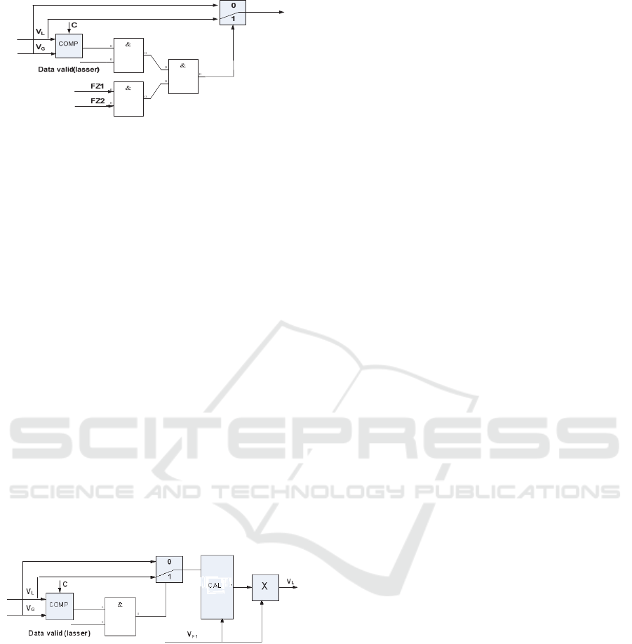
Figure 7: auto-switch between laser velocimeter and roller
speed when cutting head
VL -real-time velocity of the strip, m/s;
VG-speed of the roller, m/s;
The measure is mainly programming in the TDC
controller of flying shear and the signal from laser
velocimeter is compared with threshold C, then logic
judgment makes roller speed switch happen.
4.2 Measures 2: In Considering the
Backward Slip Situation, using the
F1 Velocity Instead of the Feedback
Value from the Roller Encoder,
When Cutting Tail
As shown in Figure 9, speed signal from F1 in
finishing roll is most stable and not subject to
environmental influence. But in the application the
backward slip factor of steel in F1 rolling must be
considered. Use the signals from velocimeter and F1
to get the real-time backward sliding coefficient and.
Multiply the real-time F1 speed with the backward
slip coefficient, then relatively stable strip speed is
gained.
Figure 9: Real-time backward sliding coefficient calculate
when cutting tail.
The calculation formula of simplified sliding
coefficient:
K
L = VL/ VF1,
VF1- speed of F1, m/s;
5 CONCLUSIONS
Based on the analysis of the causes of abnormal
shear, the idea of using the signals of more stable to
replace the existing signal in the cutting head and
tail cutting process is put forward. In this way,
abnormal signals are switched to reserved ones, and
abnormal shear due to abnormal signal inputs was
reduced to 0.32%. Meanwhile, down time of the
equipments is decreased by 72% and production
coefficient and production efficiency are improved
as well.
REFERENCES
OUYANG Xiang-xin, Principle And Operation Of The
Auto-Control System For Flying Shears, SOUTHERN
METALS,(134), pp. 30-33, 2003.
Masahiro Kayama etc, Advanced plant maintenance and
control system.7th
.
Conf
.
On steel roiling, Cln'ba,
Japan, pp.20-23, 1998.
Jiro Jumayama etc: Information and control system
technology for iron and steel plants . Hitachi
Review,Japan, pp.18-23, 1996.
ISME 2015 - Information Science and Management Engineering III
396
ISME 2015 - International Conference on Information System and Management Engineering
396
