
Analysis on Output Polarization Characteristics of Fiber Comb
Filters based on Polarization-Diversity Loop Structure
Songhyun Jo
1
, Kyoungsoo Park
1
, Sung Wook Choi
1
, Seul Lee Lee
1
, Jun Hyeog Jeong
2
,
Jihoon Kim
2
and Yong Wook Lee
1,2
1
School of Interdisciplinary Program of Biomedical Mechanical & Electrical Engineering, Pukyong National University,
45 Yongso-ro, Nam-gu, Busan 608-737, Korea, Republic of
2
School of Electrical Engineering, Pukyong National University, 45 Yongso-ro, Nam-gu, Busan 608-737, Korea, Republic of
Keywords: Comb Filter, Solc-Type Filter, Lyot-Type Filter, Polarization-Diversity Loop, Polarization-Maintaining Fiber.
Abstract: The output states of polarization (SOP’s) were investigated within the bandwidth of a filter channel (0.8 nm)
for a variety of optical fiber comb filters based on polarization-diversity loop structure including a zeroth-
order comb filter, first-order Lyot-type and Solc-type comb filters, and a second-order Solc-type comb filter.
The output SOP’s (SOP
out
’s) of the filters were calculated at a flat-top band operation mode of each filter for
four different input SOP’s (SOP
in
’s) except for the zeroth-order filter. It was found that the SOP
out
of each
filter had unique dependence on wavelength. Specifically, the SOP
out
’s of first-order and second-order comb
filters vary periodically with spectral periods of a channel bandwidth (0.8 nm) and its half (0.4 nm),
respectively. If an output linear polarizer is located at the output port of each filter, the specific portion of
transmission spectra can be passed or rejected, and the rejected band can be continuously tuned in a limited
wavelength range by controlling the SOP
in
. Moreover, the SOP
in
can be figured out by analyzing the location
of the spectral dip at the output transmission spectra obtained above by using the output polarizer.
1 INTRODUCTION
A polarization-diversity loop structure (PDLS),
which can form a Sagnac interferometer loop using a
polarization beam splitter (PBS), has been used to
eliminate the dependence of input polarization in
nonlinear optical switching applications (Morioka et
al., 1993). Fiber comb filters based on the PDLS are
capable of wavelength switching of multiwavelength
filter channels, which is difficult to be realized in a
conventional fiber comb filter that uses an optical
fiber coupler (Fang and Claus, 1995). Solc-type
birefringence combination have been incorporated to
implement high-order transmission spectra including
flat-top or narrow band spectra in first-order and
second-order fiber comb filters based on the PDLS
(Lee et al., 2005). Recently, a first-order Lyot-type
fiber comb filter based on the PDLS was
demonstrated, and its output state of polarization
(SOP) was investigated (Jo et al., 2015). But the
output SOP’s (SOP
out
’s) of the Solc-type filters
already reported have not been analyzed yet. Among
those PDLS-based comb filters, a zeroth-order comb
filter has a comb-like transmission spectrum whose
transmittance is expressed as only a sinusoidal
function (Lee et al., 2003), and both first-order and
second-order Solc-type filters have flat-top and
narrow band transmission spectra (Lee et al., 2008).
Moreover, the first-order Lyot-type comb filter has
flat-top and lossy flat-top band transmission spectra
(Jo et al., 2015).
Here, the SOP
out
’s of these filters such as a zeroth-
order comb filter, first-order Lyot-type and Solc-type
ones, and a second-order Solc-type one are analyzed
within the bandwidth of a filter channel (0.8 nm). The
SOP
out
’s of the filters were calculated at a flat-top
band operation mode of each filter for four different
input SOP’s (SOP
in
’s) except for the zeroth-order
filter. It was found that the SOP
out
of each filter had
unique dependence on wavelength. Specifically, the
SOP
out
’s of first-order and second-order comb filters
vary periodically with spectral periods of a channel
bandwidth (0.8 nm) and its half (0.4 nm), respectively.
If an output linear polarizer is located at the output
port of each filter, the specific portion of transmission
spectra can be passed or rejected, and the rejected
Jo, S., Park, K., Choi, S., Lee, S., Jeong, J., Kim, J. and Lee, Y.
Analysis on Output Polarization Characteristics of Fiber Comb Filters based on Polarization-Diversity Loop Structure.
DOI: 10.5220/0005635400470050
In Proceedings of the 4th International Conference on Photonics, Optics and Laser Technology (PHOTOPTICS 2016), pages 49-52
ISBN: 978-989-758-174-8
Copyright
c
2016 by SCITEPRESS – Science and Technology Publications, Lda. All rights reserved
49
band can be continuously tuned in a limited
wavelength range by controlling the SOP
in
. Moreover,
the SOP
in
can be figured out by analyzing the location
of the spectral dip at the output transmission spectra
obtained above by using the output polarizer.
2 OUTPUT POLARIZATION
ANALYSIS
2.1 Filter Structures for SOP
out
Analysis
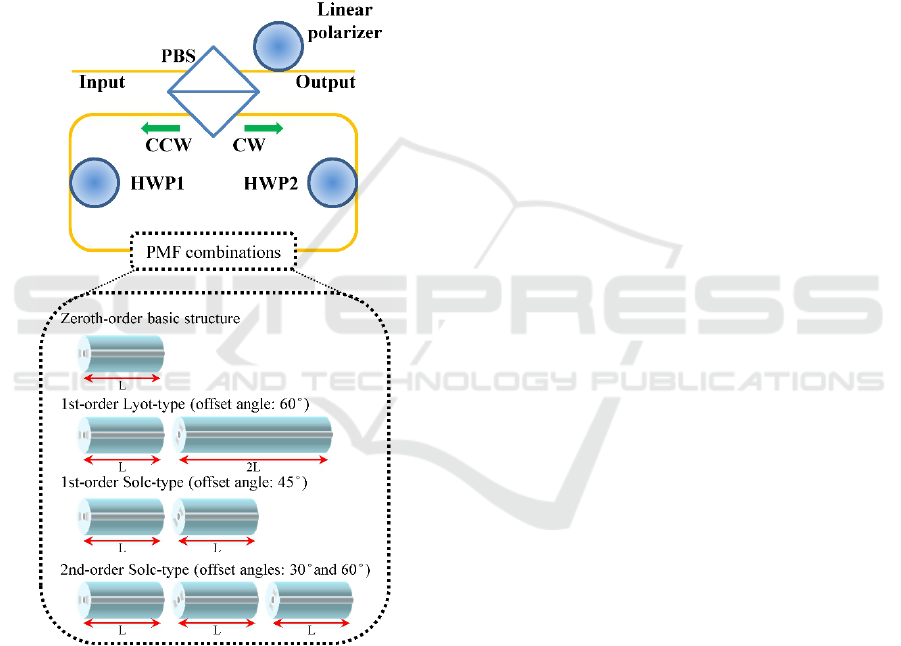
Figure 1: Schematic diagram for SOP
out
analysis of optical
fiber comb filters based on PDLS.
The schematic diagram for the SOP
out
analysis of
PDLS-based fiber filters is illustrated in figure 1.
Polarization-maintaining fiber (PMF) combinations
in the figure represent the composition of PMF
segments used for each filter. The PMF segments in
the Lyot- and Solc-type filters used in the SOP
out
analysis were arranged by using the birefringence
combination styles of Lyot and Solc filters,
respectively. Input light coming out of the PBS
decomposes into two polarization components such
as linear horizontal polarization (LHP) and linear
vertical polarization (LVP) ones. The LHP and LVP
components circulate through the Sagnac loop of the
PDLS in clockwise (CW) and counterclockwise
(CCW) directions, respectively. Then, the first-order
Lyot-type filter has two PMF segments spliced with a
60° offset between their principal axes (Jia, et al.,
2002). The lengths of the two PMF segments are L
and 2L. In the case of the first-order and second-order
Solc-type filters, all PMF segments used in them have
an identical length L, and they are concatenated with
a 45° offset (first-order) and a 30° offset (second-
order) between the principal axes of two adjacent
PMF segments, respectively.
2.2 Wavelength Dependence of SOP
out
Owing to the wavelength dependence of the SOP
out
,
new transmission spectra can be obtained if we locate
a polarizer at the output port of each filter. In order to
achieve this, the orientation angle of the polarizer was
fixed at 45° with respect to the horizontal axis of the
PBS. For four different specific SOP
in
’
s such as 45°
linear polarization (LP), 135° LP, right circular
polarization (RCP), and left circular polarization
(LCP), the transmission spectra of each filter were
calculated in the flat-top band mode except for the
zeroth-order comb filter, as shown in figure 2. The
zeroth-order filter, as shown in figure 2(a), results in
only constant losses for the four SOP
in
’s without
spectral shape changes. The first-order Lyot-type and
Solc-type filters have totally different spectra with
respect to the SOP
in
, as shown in figures 2(b) and 2(c),
respectively. Their transmission spectra have one
channel or two channels within the channel
bandwidth (0.8 nm) when they have no or one
rejection band, respectively. As can be seen from
figure 2(d), two or three channels of the second-order
Solc-type filter are created within 0.8 nm, which
results from one or two rejection bands, respectively.
The rejection band results from the existence of 135°
LP in the SOP
out
because the polarizer is oriented at
45°. In particular, the wavelength of the rejection
band that separates the channel can be adjusted
according to the SOP
in
.
As mentioned above, in the zeroth-order filter,
only a transmission loss varies without spectral shape
changes as the SOP
in
changes. In the first-order Lyot-
type filter, the transmission spectrum does not have a
rejection band at an SOP
in
of 135° LP but possesses
one rejection band at other SOP
in
’s. When the SOP
in
varies from 135° LP to RCP via LCP and 45° LP,
rotating in a CCW direction around the axis of LHP
PHOTOPTICS 2016 - 4th International Conference on Photonics, Optics and Laser Technology
50
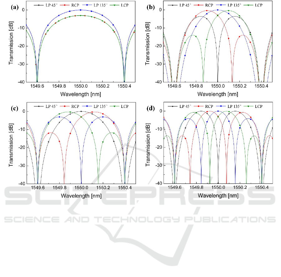
Figure 2: Calculated transmission spectra with respect to four different SOP
in
’s in (a) zeroth-order comb filter, (b) first-order
Lyot-type filter, (c) first-order Solc-type filter, and (d) second-order Solc-type filter.
on the Poincare sphere, this rejection band moves
from the shorter wavelength dip to the pass band
center of one channel, showing redshift, as shown in
figure 2(b). Similarly, in the first-order Solc-type
filter, the rejection band in its transmission spectrum
also shows redshift while the SOP
in
varies from 135°
LP to RCP via LCP and 45° LP, as shown in figure
2(c). But the initial spectral location of the rejection
band is the pass band center, which is different from
the case of the first-order Lyot-type filter. Finally, in
the second-order Solc-type filter, two rejection bands
appear except for at the SOP
in
of 45° LP and exhibit
redshift while SOP
in
changes from 135° LP to RCP
via LCP and 45° LP, as shown in figure 2(d). It is
confirmed from figure 2 that the specific portion of
transmission spectra can be passed or rejected by
controlling the SOP
in
if a linear polarizer is located at
the output port of each filter, except for the zeroth-
order filter. Moreover, it is found that modulated
spectra can be continuously tuned in a limited spectral
range in high-order filters.
Figure 3 shows the spectral variations of the
SOP
out
’s of four filters, theoretically obtained at the
analysis points (λ
n
) equally spaced in wavelength,
with respect to two specific SOP
in
’s such as 45° LP
and RCP in the flat-top band mode except for the
zeroth-order filter. Filled and empty geometries
indicate SOP’s that lie on northern and southern
hemispheres of the Poincare sphere, respectively.
Except for the zeroth-order filter, the SOP
out
represents vibrations of ellipses of the same
orientation (45° or 45°) whose eccentricity varies
from 0 on the equator to 1 at the north and south
poles of the Poincare sphere, respectively. The SOP
in
dependence of the transmission spectrum of each
filter, shown in figure 2, can be explained from figure
3. For example, if the SOP
out
is 45° LP or 135° LP,
the output of the polarizer shown in figure 1, which
has an orientation angle of 45° with respect to the
horizontal axis of the PBS, exhibits no insertion loss
(IL) or complete rejection, respectively.
The SOP
out
of the zeroth-order filter is wavelength-
independent and located on the opposite side of the
SOP
in
on the Poincare sphere, i.e., orthogonal to the
SOP
in
. On the contrary, the SOP
out
’s of three
remaining comb filters are wavelength-dependent
Analysis on Output Polarization Characteristics of Fiber Comb Filters based on Polarization-Diversity Loop Structure
51

and vary periodically with spectral periods of a
channel spacing (0.8 nm) or its half. The spectral
period of the SOP
out
evolution is the filter channel
spacing in the first-order filter and its half in the
second-order filter. In each filter, it is found that the
SOP
out
at the same analysis point is different
according to the SOP
in
, which results in the SOP
in
dependence of the output spectrum of each filter in
figure 2. In other words, it is possible to figure out the
SOP
in
of each filter except for the zeroth-order filter
by analysing output spectra obtained in the
experimental setup shown in figure 1.
Figure 3: Calculated spectral variations of SOP
out
’s of four
filters with respect to two specific SOP
in
’s such as 45° LP
and RCP.
3 CONCLUSIONS
In this paper, the SOP
out
’s of PDLS-based comb
filters such as a zeroth-order comb filter, first-order
Lyot-type and Solc-type ones, and a second-order
Solc-type one were investigated within one channel
bandwidth (0.8 nm). It was found that the SOP
out
of
the zeroth-order filter was wavelength-independent
and orthogonal to the SOP
in
. On the contrary, the
SOP
out
’s of three remaining comb filters are
wavelength-dependent and vary periodically with
spectral periods of the channel spacing (0.8 nm) or its
half. Owing to this wavelength dependence of the
SOP
out
’s of the filters, one or two rejection bands
appear in the output spectrum if a linear polarizer is
located at their output port. When the SOP
in
varies
from 135° LP to RCP via LCP and 45° LP except for
the zeroth-order comb filter, rotating in a CCW
direction around the axis of LHP on the Poincare
sphere, this rejection band exhibits redshift. In
particular, the rejection band was possible to be
continuously tuned in a limited wavelength range in
the high-order filters by controlling the SOP
in
.
ACKNOWLEDGEMENTS
This work was supported by the National Research
Foundation of Korea (NRF) grant funded by the
Korea government (MSIP) (No.
2013R1A2A2A01068390). This research was also
supported by a grant from Marine Biotechnology
Program (20150220) funded by the Ministry of
Oceans and Fisheries, Korea.
REFERENCES
Morioka, T., Inoue, K., and Oda, K. (1993) ‘Polarization
independent frequency conversion by fiber four-wave
mixing with a polarization-diversity technique’, IEEE
Photonics Technology Letters, vol. 5, August, pp. 947-
949.
Fang, X., and Claus, R. O. (1995) ‘Polarization-
independent all-fiber wavelength-division multiplexer
based on a Sagnac interferometer’, Optics Letters, vol.
20, October, pp. 2146-2148.
Lee, Y. W., Kim, H., Jung, J., and Lee, B. (2005)
‘Wavelength-switchable flat-top fiber comb filter based
on a Solc type birefringence combination’, Optics
Express, vol. 13, February, pp. 1039-1048.
Jo, S., Kim, Y., Song, H., and Lee, Y. W. (2015) ‘Study on
Transmission and output polarization characteristics of
first-order Lyot-type fiber comb filter using
polarization-diversity loop’, IEEE Photonics Journal,
vol. 7, August.
Lee, Y. W., Han, K. J., Lee, B., and Jung, J. (2003)
‘Polarization-independent all-fiber multiwavelength-
switchable filter based on a polarization-diversity loop
configuration’, Optics Express, vol. 11, December, pp.
3359-3364.
Lee, Y. W., Kim, H., and Lee, Y. W. (2008) ‘Second-order
all-fiber comb filter based on polarization-diversity
loop configuration’, Optics Express, vol. 16, March, pp.
3871-3876.
Jia, Z., Chen, M., and Xie, S. (2002) ‘Label erasing
technique employing Lyot-Sagnac filter’, Electronics
Letters, vol. 38, November, pp. 1563-1564.
PHOTOPTICS 2016 - 4th International Conference on Photonics, Optics and Laser Technology
52
