
Kinect V2 for Upper Limb Rehabilitation Applications
A Preliminary Analysis on Performance Evaluation
Giorgia Lupinacci, Gianluca Gatti, Agostino Angilica and Maurizio Muzzupappa
Dept. of Mechanical, Energy and Management Engineering (DIMEG), University of Calabria,
V. P. Bucci, Arcavacata di Rende (CS), 87036, Italy
Keywords: Upper Limb Rehabilitation, Upper Limb Joints Tracking, Kinect V2.
Abstract: Many systems have been developed to facilitate upper limb rehabilitation procedures in human subjects
affected by trauma or pathologies and to retrieve information about patient performance. The Microsoft
Kinect sensor can be used in this context to track body motion and detect objects. In order to evaluate the
usability of this device in the upper limb rehabilitation field, a comparison with a marker-based system is
presented in this paper. The upper limb motion is specifically considered and the performance on its
detection and tracking is evaluated. The effect of the relative location between the Kinect and the observed
subject is also investigated through experimental tests performed in different configurations.
1 INTRODUCTION
Modern upper limb rehabilitation systems use
motion tracking technologies to evaluate patient
performance, to aid limb motion in robotic assisted
rehabilitation techniques or to allow interaction with
virtual reality (Zhou and Hu, 2008). Shoulder, elbow
and wrist joints tracking, is a necessary step for
motion classification and recognition (Pimentel do
Rosàrio, 2014). Furthermore, upper limb tracking
allows to develop patient-specific therapies and is
used to create serious games that induce motor
recovery in a stimulating environment (Burke et al.,
2009). Assisted motion control is also fundamental
for the application of autonomous or semi-
autonomous systems for motor recovery and to make
rehabilitative experience possible at home (Prieto et
al.,
2014). Marker-less motion tracking systems for
gaming are proposed as an alternative to marker-
based systems (Moeslund et al., 2006; Lange et al.,
2011) (usually adopted for motion analysis), because
they are easy to use and less expensive. Moreover, a
marker-less system is more flexible, because it
offers the advantage to be used in several
environments and configurations.
One of the most interesting marker-less systems
available nowadays is the Microsoft Kinect
TM
(Kinect for Windows features, 2015). The device is
able to retrieve the position of 25 human body joints
and track up to six human subjects at the same time.
It predicts the body joints from a single depth image.
From July 2014 a new version of the sensor is
available, namely the Kinect for Windows v2.0, with
improved performances respect to the first release,
thanks to the higher fidelity of depth images (Lachat
et al., 2015).
Kinect performance was studied using three main
approaches: posture detection (Clark et al., 2012;
van Diest et al., 2014; Diego-Mas and Alcaide-
Marzal, 2014), joints centre evaluation (Xu and
McGorry, 2015) and angles evaluation (Bonnechère
et al., 2014; Chang et al., 2012). In particular, Xu
and McGorry (Xu and McGorry, 2015) very recently
proposed a comparison between the first and second
generation of the Kinect and a marker-based system,
concluding that no impressive improvements are
introduced by the new version of the Kinect if the
tracking is assessed at the whole skeleton level for
static posture evaluation.
It is to be noted, however, that most of the
available studies consider only the first generation of
the Kinect (Bonnechère et al., 2014; Chang et al.,
2012; Clark et al., 2012; van Diest et al., 2014), so
the advantages of the second generation are not
completely addressed, especially in the upper limb
rehabilitation field.
The aim of this work is thus to validate the
reliability of the second generation of the Kinect
when adopted for upper limb rehabilitation. The
study was conducted by taking into consideration (i)
Lupinacci, G., Gatti, G., Angilica, A. and Muzzupappa, M.
Kinect V2 for Upper Limb Rehabilitation Applications - A Preliminary Analysis on Performance Evaluation.
DOI: 10.5220/0005659201310138
In Proceedings of the 9th International Joint Conference on Biomedical Engineering Systems and Technologies (BIOSTEC 2016) - Volume 1: BIODEVICES, pages 131-138
ISBN: 978-989-758-170-0
Copyright
c
2016 by SCITEPRESS – Science and Technology Publications, Lda. All rights reserved
131
the possibility to use the sensor in different positions
without calibration and (ii) the body tracking
algorithm, already integrated in the Kinect software.
A marker-based system was used to conduct the
evaluation of the upper limb tracking performance.
The upper limb motion was executed by an healthy
subject guided by the use of a specific end-effector
as to emulate the movements usually asked to the
patient during a robot-assisted rehabilitative session,
e.g. the “reaching” and the “side to side” exercise
(Volpe et al., 2008; Frisoli et al., 2012; Lam et al.,
2008). The performances of the Kinect are compared
to that of a marker-based system, for specific
complex movements, affecting both the shoulder and
elbow rotation simultaneously.
2 MATERIALS AND METHODS
Upper limb tracking was performed using the second
version of the Microsoft Kinect for Windows and a
stereo-photogrammetric optical system, the
Optitrack (NaturalPoint, Inc. - Optical Tracking
Solutions, 2015), consisting of 8 Flex13 cameras
acquiring up to a frequency of 120 Fps. For body
tracking, the Kinect body model and joints position
were obtained from the associated Software
Development Kit (SDK) v2.0 (Microsoft, Kinect for
Windows, 2015), working at up to 30 Fps. For the
Optitrack system, the NatNet SDK v2.7 (Natural
Point Inc. - Optical Tracking Solutions, 2015) and
the Motive 1.7.5 software (Natural Point Inc. -
Optical Tracking Solutions, 2015) was adopted to
capture the body joints position in conjunction with
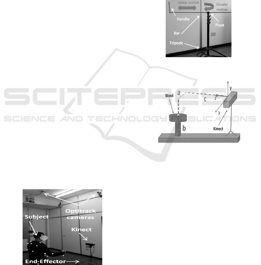
a motion capture suit and reflective markers. Figure
1 shows the set up for the upper limb tracking. In the
figures both the Kinect sensor and the Optitrack
cameras are indicated, as well as the corresponding
coordinate systems used to retrieve numerical
values.
Figure 1: Experimental setup for upper limb tracking.
2.1 Upper Limb Tracking
During the study presented in this work, it was asked
an healthy subject to make a set of movements using
a passive end-effector. In particular, the end-effector
which was visible in Figure 1 and is now shown in
the detail of Figure 2, consisted of a tripod and a bar
fixed on it. It was made to constrain the hand
movement of the subject to a circular or a linear
motion, so that a reference trajectory was available
for validation. Each session was recorded by using
both the Kinect and the Optitrack system.
Figure 2: End-effector used for upper limb motion. It
consists of a tripod and a bar.
Figure 3: Schematic representation of Kinect position
relative to the subject for upper limb tracking. Parameters
are given in Table 1.
The healthy subject was seated on a stool, placed
in the field of view of the Optitrack cameras and the
Kinect was placed in six different positions as
illustrated in Figure 3, but oriented so as it was
facing the stool. The different positions where the
Kinect was located are defined to be at the right,
middle and left position relative to the axis
orthogonal to the subject front plane, as defined in
Table 1. For each of these positions, the Kinect was
located at two different distances from the floor,
respectively at about 800 mm and 1500 mm. In
Table 1 these positions are summarized and labeled
from K1 to K6 for ease of reference. The subject
was wearing a motion capture suit with reflective
markers to identify the shoulder, elbow and wrist
joint, as shown in Figure 1. Such analysis is
BIODEVICES 2016 - 9th International Conference on Biomedical Electronics and Devices
132
performed to investigate if the Kinect position
relative to the subject was somehow affecting the
overall tracking procedure. A circular motion and a
linear motion were thus executed by the right hand
of the healthy subject for each position of the
Kinect, as described above. It is worth noting that
the healthy subject was asked not to rotate the wrist
during the constrained motion, even if some small
effect due to this compliant requirement are
expected to affect the obtained results reported in
Section 3.
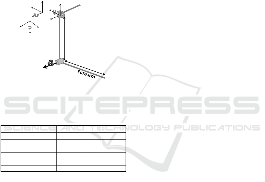
Figure 4: Schematic model of the upper limb with
geometric parameters and joints variable, as defined in
(Mihelj, 2006).
Table 1: Definition of the six Kinect position used for
upper limb tracking.
Position a [mm]
b[mm] c [mm]
K1 – right down 800 800 -2000
K2 – right up 800 1500 -2000
K3 – middle down 0 800 -2000
K4 – middle up 0 1500 -2000
K5 – left down -800 800 -2000
K6 – left up -800 1500 -2000
The Kinect and the Optitrack frames were
synchronized using the timestamp for direct
comparison.
To determine the shoulder and elbow angles
from the coordinates of the position of the shoulder,
elbow and wrist joints obtained from the two optical
systems, a 4 degree-of-freedom (DOF) inverse
kinematic model of the human arm was used
(Mihelj, 2006). A schematic model of the upper limb
with geometric parameters is represented in Figure
4. The shoulder is modeled as a ball-and-socket joint
with rotation axis for abduction-adduction (angle
q
1
), flexion-extension (angle q
2
) and internal-
external rotation (angle q
3
).
With reference to Figure 4, l
u
and l
f
are,
respectively, the arm and forearm lengths. The
RMSDs between Optitrack angles variation and
Kinect angles variation were computed, to give an
indication of the difference between the two
systems.
The trajectory described by the wrist as
computed from the two optical system for each
session, is also used to assess the performance of the
two motion tracking systems. In particular, a best-fit
plane was determined on the set of points
corresponding to the wrist position during motion.
This is because the motion constrained by the end-
effector was planar and this allowed to preliminary
filter the results. Once projected on the
corresponding best-fit plane, a second fitting was
performed on the projected trajectories to fit a circle
and a line, respectively, for the circular motion and
for the linear motion of the hand grasping the end-
effector. The RMSD of the residual errors of each
fitting procedure, the radius of the fitted circle and
the range of motion (RoM) for each trajectory were
computed.
3 RESULTS
For upper limb tracking, the shoulder and elbow
angles are computed for each of the 12 sessions (one
circular and one translational motion for the six
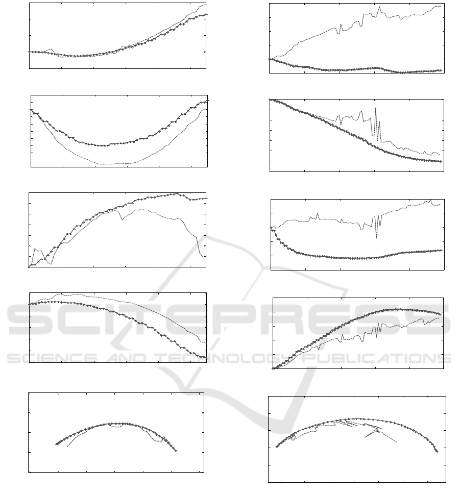
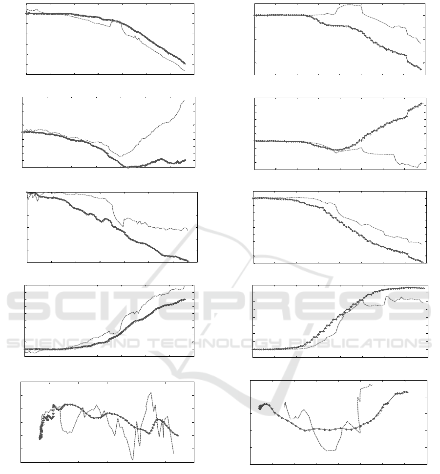
Kinect configurations). The sample in Figure 5
represents the results relative to the circular motion
executed by the participant using the end-effector,
with the Kinect at the middle down position K3, as
defined in Table 1. In Figure 5(a-d) the variation of
the angles q
1
,…q
4
, are respectively showed, as
obtained from the Kinect and Optitrack joints data,
for a circular motion of the end-effector with the
Kinect in position K3. Also, in Figure 5(e) the
trajectories computed using the Kinect and the
Optitrack data are showed.
Figure 6 illustrates the same information
represented in Figure 5, but relative to a circular
motion captured with the Kinect at the right down
position K1, as defined in Table 1. Figure 7 and
Figure 8 represent the results relative to the linear
motion with the Kinect at the middle down position
K3 and at the right down position K1, respectively.
It is worth noting that the parameters of the
Kinect and Optitrack body model do not correspond
to each other, and this is because of the intrinsic
identification of joints location performed by the two
systems. This means, in particular, that the arm and
forearm length, as identified by the systems, are in
general different, and they also vary along the
acquisition time. For the Kinect, the identified joints
location are affected mainly by the intrinsic system
l
u
l
f
Shoulder
Elbow
z3
q4
Arm
z0
x0
y0
y1
z1
x1
y2
z2
x2
q1
q2
q3
Kinect V2 for Upper Limb Rehabilitation Applications - A Preliminary Analysis on Performance Evaluation
133
setting, ambient light and sensor resolution. For the
Optitrack, they are affected mainly by the body suit
and the reflective marker location. To have a better
insight into these effects, Table 2 and 3 reports the
mean and STD of l
u
and l
f
as identified by the two
optical systems, for the circular and linear motion of
the end-effector, respectively.
Comparing Figure 5 to Figure 6, it can be seen
that a better match between Optitrack and Kinect
data is achieved for the first dataset. Furthermore,
the wrist trajectory computed by the Kinect (Figure
6 (e)) presents some noise due to the high variation
in the identification of the forearm and arm lengths,
as explained above. In particular, from Table 2, it is
observed that the STDs of l
u
and l
f
obtained by the
Kinect at the middle down pose (K3), are the lowest
compared to all the Kinect acquisitions. The STD of
l
u
when the Kinect is in position K5 is lower than for
K3 but the STD of l
f
is greater than for K3. The same
observations can be done comparing Figure 7 and
Figure 8. In the middle down configuration, indeed,
the subject was completely visible and no joints
occlusion occurred during the acquisitions.
In Table 4 and Table 5 the RMSDs obtained
from the angles variations of the Optitrack and
Kinect data are reported, for circular motions and
linear motions, respectively. The lower trend of
these values for middle positions (K3 and K4) of the
Kinect confirms that this is the preferable position
for the sensor. Tables 6 and 7 summarize the results
obtained in terms of the wrist trajectory for the
circular and linear motion, respectively. In Table 6
the radius associated to each circular trajectory after
circle fitting, and the RoM are reported, while for
the linear motion the RoM is reported in Table 7.
Table 2: Mean value of the arm length l
u
, and forearm
length l
f
identified by the two optical systems along the
acquisition frames, for the circular motion and for the
different Kinect positions as from Table 1. The value in
parenthesis is the STD () of the correspondent
distribution. The sub-script “K” stands for Kinect, while
the “O” stands for Opitrack.
Circular Motions
K1 K2 K3 K4 K5 K6
l
u
[mm]
K
()
280.6
(12.6)
204.6
(18.0)
202
(4.4)
224.6
(20.5)
188.1
(2.3)
230.7
(10)
O
()
286.0
(6E-4)
286.0
(7E-4)
276.5
(4E-3)
286
(1E-3)
286
(1E-3)
286
(8E-4)
l
f
[mm]
K
()
234
(3)
213.5
(18.3)
203.6
(0.8)
215.3
(11.2)
192
(11.1)
223
(8.6)
O
()
285
(7.2)
275.4
(12.0)
252.0
(12.5)
263.2
(9.4)
253.3
(2)
268.5
(9.2)
Table 3: Mean value of the arm length l
u
, and forearm
length l
f
identified by the two optical systems along the
acquisition frames, for the circular motion and for the
different Kinect positions as from Table 1. The value in
parenthesis is the STD () of the correspondent
distribution. The sub-script “K” stands for Kinect, while
the “O” stands for Opitrack.
Linear Motions
K1 K2 K3 K4 K5 K6
l
u
[mm]
K
()
230.5
(11.5)
222.4
(7.7)
248
(4.1)
211
(19.4)
243.5
(6.8)
230.7
(10)
O
()
286.0
(1E-3)
286
(4E-4)
286
(6E-4)
286
(4E-4)
286
(4E-4)
285.8
(9E-4)
l
f
[mm]
K
()
239.7
(25.3)
216.0
(7)
187.5
(1.6)
232.6
(16.3)
222
(7.2)
223
(8.5)
O
()
274.0
(4.4)
260.4
(8.4)
236.0
(8.2)
243.6
(7.5)
268.2
(14)
268.5
(9.2)
Table 4: RMSDs obtained comparing the arm angles
variations for Kinect and Optitrack for the circular
motions of the end-effector and for the six different Kinect
configurations from Table 1.
Circular Motions
K1 K2 K3 K4 K5 K6
RMSD q
1
2.5 32.2 6 1.1 5.7 3
RMSD q
2
2.0 10.6 3.1 4.5 5.7 4
RMSD q
3
20.0 53.0 21.2 4.0 2.6 31
RMSD q
4
4.9 17.8 8.4 11.8 3.6 2.7
Table 5: RMSDs obtained comparing the arm angles
variations for Kinect and Optitrack for the linear motion of
the end-effector and for the six different Kinect
configurations from Table 1.
Linear Motions
K1 K2 K3 K4 K5 K6
RMSD q
1
17.05 7.4 6.7 7.9 3.8 6.7
RMSD q
2
16.1 9.2 4.5 1.1 4.5 1.8
RMSD q
3
27.7 7.6 8.5 6.0 20.4 32.0
RMSD q
4
16.4 5.7 8.4 4.4 7.7 3.7
Table 6: Results of the wrist trajectories for circular
motion. Circle-fitted radius and estimated RoM, for the six
different Kinect configurations as from Table 1. The “K”
stands for Kinect and the “O” stands for Optitrack.
K1 K2 K3 K4 K5 K6
Radius
[mm]
K 180 102 95.6 118 122 183
O 179.1 163.3 119.6 201.4 198.7 176.5
RoM
[deg]
K 105.2 111.7 129.0 96.5 114.3 148
O 92.3 102.1 121.3 76.8 111.8 173.3
Table 7: Results of the wrist trajectories for linear motion.
Estimated RoM, for the six different Kinect configurations
as from Table 1. The “K” stands for Kinect and the “O”
stands for Optitrack.
K1 K2 K3 K4 K5 K6
RoM
[mm]
K 234.2 240 263.4 228.5 273.3 293.8
O 312.2 326 284.9 308.6 292.2 316.9
BIODEVICES 2016 - 9th International Conference on Biomedical Electronics and Devices
134
(a)
(b)
(c)
(d)
(e)
Figure 5: Results for the circular motion of the end-
effector using the right arm, with Kinect in position K3.
(a)
q
1
, (b)
q
2
, (c)
q
3
, (d)
q
4
, (e) estimated wrist
trajectory by Optitrack (spotted lines) and Kinect
(discontinue lines). The axes x and z represent the
coordinates of the best-fit plane determined on the set of
points corresponding to the wrist position during motion.
For the circular motions, the mean value of the
difference between the radius of the circle fitted on
the Kinect data and on the Optitrack data is 42(36)
mm, where the value in parentheses represents the
(a)
(b)
(c)
(d)
(e)
Figure 6: Results for the circular motion of the end-
effector using the right arm, with Kinect in position K2.
(a)
q
1
, (b)
q
2
, (c)
q
3
, (d)
q
4
, (e) estimated wrist
trajectory by Optitrack (spotted lines) and Kinect
(discontinue lines). x and z are the coordinate of the best-
fit plane determined on the set of points corresponding to
the wrist position during motion.
STD of the correspondent distribution. Instead, the
mean difference between the ROM computed from
the Kinect data and from the Optitrack data, is
13(8.3) deg. Finally, the mean difference between
0 10 20 30 40 50
-5
0
5
10
15
Frame
q
1
[deg]
0 10 20 30 40 50
-16
-14
-12
-10
-8
-6
-4
-2
0
2
4
Frame
q
2
[deg]
0 10 20 30 40 50
0
2
4
6
8
10
12
14
Frame
q
3
[deg]
0 10 20 30 40 50
-50
-40
-30
-20
-10
0
10
Frame
q
4
[deg]
-150 -100 -50 0 50 100 150
-100
-50
0
50
100
x [mm]
z [mm]
0 20 40 60 80 100
-10
0
10
20
30
40
Frame
q
1
[deg
]
0 20 40 60 80 100
-70
-60
-50
-40
-30
-20
-10
0
Frame
q
2
[deg]
0 20 40 60 80 100
-60
-40
-20
0
20
40
Frame
q
3
[deg]
0 20 40 60 80 100
0
20
40
60
80
100
Frame
q
4
[deg]
-150 -100 -50 0 50 100 150
-150
-100
-50
0
50
100
x [mm]
z [mm]
Kinect V2 for Upper Limb Rehabilitation Applications - A Preliminary Analysis on Performance Evaluation
135
(a)
(b)
(c)
(d)
(e)
Figure 7: Results for the linear motion of the end-effector
using the right arm, with Kinect in position K3. (a)
q
1
,
(b)
q
2
, (c)
q
3
, (d)
q
4
, (e) estimated wrist trajectory by
Optitrack (spotted lines) and Kinect (discontinue lines).
The axes x and z represent the coordinates of the best-fit
plane determined on the set of points corresponding to the
wrist position during motion.
the ROM on the linear motion of the hand on the bar
is equal to 51.4(33.3) mm.
From Figures 5, Figure 6, Figure 7 and Figure 8
(a)
(b)
(c)
(d)
(e)
Figure 8: Results for the linear motion of the end-effector
using the right arm, with Kinect in position K2. (a)
q
1
,
(b)
q
2
, (c)
q
3
, (d)
q
4
, (e) estimated wrist trajectory by
Optitrack (spotted lines) and Kinect (discontinue lines). x
and z are the coordinate of the best-fit plane determined on
the set of points corresponding to the wrist position during
motion.
it is seen that there are some offsets between the
angles estimated by the two systems, and this is due
to the different body model inherently adopted by
0 20 40 60 80 100 120 140
-30
-25
-20
-15
-10
-5
0
5
Frame
q
1
[deg]
0 20 40 60 80 100 120 140
-5
-4
-3
-2
-1
0
1
2
3
4
5
Frame
q
2
[deg]
0 20 40 60 80 100 120 140
-60
-50
-40
-30
-20
-10
0
Frame
q
3
[deg]
0 20 40 60 80 100 120 140
-5
0
5
10
15
20
25
30
35
40
45
Frame
q
4
[deg]
-100 -50 0 50 100 150 200
-15
-10
-5
0
5
10
15
x [mm]
z [mm]
0 10 20 30 40 50 60 70 80
-25
-20
-15
-10
-5
0
5
Frame
q
1
[deg]
0 10 20 30 40 50 60 70 80
-8
-6
-4
-2
0
2
4
6
8
10
12
Frame
q
2
[deg]
0 10 20 30 40 50 60 70 80
-45
-40
-35
-30
-25
-20
-15
-10
-5
0
5
Frame
q
3
[d
eg
]
0 10 20 30 40 50 60 70 80
-5
0
5
10
15
20
25
30
35
40
Frame
q
4
[deg]
-150 -100 -50 0 50 100 150 200 250
-15
-10
-5
0
5
10
x [mm]
z [ mm]
BIODEVICES 2016 - 9th International Conference on Biomedical Electronics and Devices
136

the Kinect and Optitrack, as discussed above. For
this reason it is not expected that the angles obtained
from the data captured by the two systems are the
same. The comparison between the two systems in
terms of RoM should be then taken as a qualitative
indication only.
4 DISCUSSION
This paper presented a preliminary investigation on
the expected results and performance that could be
obtained when using the marker-less Kinect sensor
for upper limb motion tracking, with specific
application to the rehabilitation of the upper limb. In
particular, the aim of this study was focused on the
Kinect v2, recently released by the Microsoft. An
auxiliary marker-based Optitrack system, composed
by 8 cameras and motion capture suit with reflective
markers, was used as reference. The Kinect marker-
less system can be used to detect objects in the 3D
space with an accuracy close to the centimetre
(Lachat et al., 2015). The accuracy of the Optitrack
system has been estimated to be of the order of the
millimetre (Carse et al., 2013). So, the Optitrack
system exhibits an accuracy higher than that of the
Kinect, and this confirm its use as a reference.
For the upper limb tracking procedure, a realistic
experimental setup was created. An healthy subject
(participant) was asked to execute specific motions
grasping an end-effector, in order to reproduce a
robotic-assisted rehabilitation procedure (Zhou and
Hu, 2008). It was observed that, in order to have a
better precision and accuracy, the Kinect should be
located in front of the subject. The comparison
between the two optical systems could only give
qualitative indication on the relative precision and
accuracy in detecting upper limb tracking. This was
related to the inherently different body models
implemented in the Kinect and Optitrack software
tools. Furthermore, on the one hand the Optitrack
data were affected by the presence of the body suit,
its fitting to the participant, and by the location and
observability of the reflective markers. On the other
hand, the Kinect data were mainly affected by the
ambient lightning and by the lower resolution of the
sensors.
To check the reliability of the body model data,
the mean and STD of both the arm and forearm, as
identified by the two optical systems along the
acquired frames are calculated. It is shown that,
when the Kinect is located in front of the subject, the
deviations relative to the arm and the forearm
lengths computed by the Kinect were lower, as to
suggest that the device is more precise in such
configuration rather than in others, where it is
inclined respect to the subject. However, the results
obtained when the Kinect was in these latter
configurations do not dramatically exclude their
usability for a qualitative evaluation of the upper
limb motion. It was also observed that, if the upper
body of the subject is completely in the field of view
of the Kinect and no occlusion of the joints occurs
during motion, the body tracking allows to
approximate the trajectory of the wrist with lower
noise. However, the estimate of the joints position is
not accurate, as suggested by the STD of segments
length computed using the Kinect data. Indeed,
comparing the Kinect data with the Optitrack data,
as reported in Table 2, it is possible to note that, for
every acquisition step, the Optitrack identifies the
length of the upper arm with a very low STD,
whereas the Kinect gives different mean lengths for
each acquisition step. For the Optitrack data, the
mean length of the forearm results to be variable for
each acquisition step because of the motion tracking
suit, particularly at the wrist.
5 CONCLUSIONS
This preliminary study suggested that the Kinect
may be potentially adopted for applications
involving upper limb rehabilitation. The advantages
of such a system are the low cost, no requirement for
calibration, the easy to use and to set up, and the
absence of any body marker or suit that could
inevitably involve motion artefact. However, the
main limitation is the lower resolution, compared to
the more expensive marker-based systems.
Nevertheless, such resolution, of about few tens of
millimetres for the experimental test performed here
on the upper limb, make the Kinect an interesting
tool for applications in the rehabilitation field.
Future works are aimed at carrying out a more
detailed and extensive experimental analysis
involving several healthy subjects with different
characteristics, trying to come up with a more
reliable statistical analysis and some concluding
evidence on the usability of the device for the
specific body application.
REFERENCES
Asín Prieto G., Cano-de-la-Cuerda R., López-Larraz E.,
Metrot J., Molinari M., van Dokkum, L. E. H., 2014.
Emerging Perspectives in Stroke Rehabilitation. In
Kinect V2 for Upper Limb Rehabilitation Applications - A Preliminary Analysis on Performance Evaluation
137

Emerging Therapies in Neurorehabilitation
Biosystems & Biorobotics, vol. 4, pp 3-21.
SPRINGER.
Beucher, S., 1992. The watershed transformation applied
to image segmentation. In Scanning Microscopy-
Supplement-, pp 299-299.
Bonnechère, B., Jansen, B., Salvia, P., Bouzahouene, H.,
Omelina, L., Moiseev, F., Sholukha, V., Cornelis, J.,
Van Sint Jan, S., 2014. Validity and reliability of the
Kinect within functional assessment activities:
Comparison with standard stereophotogrammetry. In
Gait & Posture, vol. 39, no.1, pp 593 – 598.
ELSEVIER.
Burke, J. W., McNeill, M. D. J., Charles, D. K., Morrow,
P. J., Crosbie, J. H., McDonough, S. M., 2009.
Optimising engagement for stroke rehabilitation using
serious games. In The Visual Computer, vol.12, no. 25,
pp 1085-1099. SPRINGER.
Carse, B., Meadows, B., Bowers, R., Rowe, P., 2013.
Affordable clinical gait analysis: An assessment of
marker tracking accuracy of a new low-cost optical 3D
motion analysis system. In Physiotherapy, vol. 99, no.
4, pp347-351. ELSEVIER.
Chang,C.-Y., Lange, B., Zhang, M., Koenig, S., Requejo,
P., Somboon, N., Sawchunk, A.A., Rizzo, A.A., 2012.
Toword pervasive physical rehabilitation using
Microsoft Kinect. In 2012 6
th
International
Conference on Pervasive Computing Technologies for
Healthcare and Workshops, PervasiveHealth 2012, pp
159-162.
Clark, R.A., Pua, Y., Fortin, K., Ritchie C., Webster, K.E.,
Denehy, L., Bryant, A.L., 2012. Validity of the
Microsoft Kinect for assessment of postural control. In
Gait & Posture, vol. 36, no.3, pp 372-577.
ELSEVIER.
Diego-Mas, J. A., Alcaide-Marzal, J., 2014. Using
Kinect
TM
sensor in observational methods for
assessing postures at work. Applied Ergonomics, vol.
45, no.4, pp 976 – 985. ELSEVIER.
Frisoli, A., Procopio, C., Chisari, C., Creatini, I.,
Bonofiglio, L., Bergamasco, M., Rossi, B.,
Carboncini, M. C., 2012. Positive effects of robotic
exoskeleton training of upper limb reaching
movements after stroke. In Journal of
Neuroengineering and Rehabilitation, vol. 9, no. 36.
BioMed Central.
Kinect for Windows features. Available from:
https://www.microsoft.com/enus/kinectforwindows/m
eetkinect/features.aspx [3August 2015]
Lachat, E., Macher, H., Mittet M. A., Landes, T.,
Grussenmeyer, P., 2015. First experiences with Kinect
v2 sensor for close range 3D modelling. In The
International Archives of the Photogrammetry,
Remote Sensing and Spatial Information Sciences,
Volum XL-5/W4.
Lam, P., Hebert, D., Boger, J., Lacheray, H., Gardner, D.,
Apkarian, J., Mihailidis, A., 2008. A haptic-robotic
platform for upper-limb reaching stroke therapy:
preliminary design and evaluation results. In Journal
of Neuroengineering and Rehabilitation, vol. 5, no. 15.
BioMed Central.
Lange, B., Chang, C., Suma, E., Newman, B., Rizzo, A.,
Bolas, M., 2011. Development and evaluation of low
cost game-based balance rehabilitation tool using the
Microsoft Kinect sensor. In Engineering in Medicine
and Biology Society, EMBC, 2011 Annual
International Conference of the IEEE, pp 1831-1834.
IEEE.
Mihelj, M., 2006. Human Arm Kinematics for Robot
Based Rehabilitation. In Robotica, vol. 24, no. 3, pp
377-383. CAMBRIDJE UNIVERSITY PRESS.
Moeslund, T. B., Hilton, A., & Krüger, V., 2006. A survey
of advances in vision-based human motion capture and
analysis. In Computer vision and image understanding,
vol. 104, no. 2, pp 90-126. ELSEVIER.
Natural Point, 2015. Inc.: Optitrack-optical motion
tracking solutions. Available from: https://
www.naturalpoint.com/.
Pimentel do Rosàrio, J.L., 2014. Biomechanical
assessment of human posture: A literature review. In
Journal of Bodywork and Movement Therapies,
vol.18, no. 3, pp 368-373. ELSEVIER.
Van Diest, M., Stegenga, J., Heinrich, J.W., Postema K.,
Verkerke, G. J., Lamoth, C. J. C., 2014. Suitability of
Kinect for measuring whole body movement patterns
during exergaming. Journal of Biomechanics, vol. 47,
no.12, pp 2925 – 2932. ELSEVIER.
Volpe, B. T., Lynch, D., Rykman-Berland, A., Ferraro,
M., Galgano, M., Hogan, N., Krebs, H.I., 2008.
Intensive Sensorimotor Arm Training Mediated by
Therapist or Robot Improves Hemiparesis in Patients
With Chronic Stroke. In Neurorehabilitation & Neural
Repair, vol. 22, no. 3, pp 305-310. SAGE.
Xu, X., McGorry, R. W., 2015. The validity of the first
and second generation Microsoft Kinect
TM
for
identifying joint center locations during static
postures. In Applied Ergonomics, vol. 49, pp 47 – 54.
ELSEVIER.
Zhou, H., Hu, H., 2008. Human motion tracking for
rehabilitation-A survey. In Biomedical Signal
Processing and Control, vol.3, no. 1, pp 1-18.
ELSEVIER.
BIODEVICES 2016 - 9th International Conference on Biomedical Electronics and Devices
138
