
Exposing Design Mistakes During Requirements Engineering by Solving
Constraint Satisfaction Problems to Obtain Minimum Correction
Subsets
Alexander Diedrich
1
, Bj
¨
orn B
¨
ottcher
1
and Oliver Niggemann
2
1
Fraunhofer IOSB-INA, Langenbruch 6, 32657 Lemgo, Germany
2
Institute for Industrial IT, Langenbruch 6, 32657 Lemgo, Germany
Keywords:
Constraint Satisfaction, Feature Models, Product Line Engineering, Minimum Correction Subsets.
Abstract:
In recent years, the complexity of production plants and therefore of the underlying automation systems has
grown significantly. This makes the manual design of automation systems increasingly difficult. As a result,
errors are found only during production, plant modifications are hindered by not maintainable automation so-
lutions and criteria such as energy efficiency or cost are often not optimized. This work shows how utilizing
Minimum Correction Subsets (MCS) of a Constraint Satisfaction Problem improves the collaboration of au-
tomation system designers and prevents inconsistent requirements and thus subsequent errors in the design.
This opens up a new field of application for constraint satisfaction techniques. As a use case, an example
from the field of automation system design is presented. To meet the automation industry’s requirement for
standardised solutions that assure reliability, the calculation of MCS is formulated in such a way that most con-
straint solvers can be used without any extensions. Experimental results with typical problems demonstrate
the practicalness concerning runtime and hardware resources.
1 INTRODUCTION
The design of an automation system is already a com-
plex and time-consuming task, today. Additionally,
the complexity of these systems will increase in the
future even more due to a higher degree of automation
and an increasing amount of their constituent parts
and environmental constraints (Fay et al., 2015). In
(Vogel-Heuser et al., 2014) it is stated that today’s
design methods are not keeping pace with the rising
complexity and it is shown that designers lack tools
for efficiently designing automation systems.
In order to create suitable tools it becomes neces-
sary to have a formalised description of design and
configuration knowledge in industrial contexts. The
knowledge can be accessed by automatic configura-
tion tools that are able to execute certain (lower-level)
design tasks and thus reduce the work for human de-
signers. This enables designers to focus more on the
specification of requirements. By making use of this
formalised knowledge the design process becomes
independent of single persons that have highly spe-
cialised skills because the knowledge is formalised
in software and thus every designer can make use of
it. Furthermore, when the software is able to design
the implementation specific details, repetitive and er-
ror prone tasks are automated. This also includes that
different design variants of a system can be generated
without additional engineering effort. Therefore, it
enables users to find the best variant to a given use-
case.
To devise such design methods it is necessary that the
initial requirements can be specified in a formal way,
because these are the basis for the subsequent auto-
matic design.
This paper describes a method to specify require-
ments for an automation system formally with an em-
phasis on cooperation between different professions
and support of interdisciplinary conflict resolution.
This is done by dividing the design work into differ-
ent categories like mechanics, visualization, security
etc. If conflicts arise during the requirements specifi-
cation the presented approach attributes each conflict
to the corresponding category and tells the user which
requirements need to be changed. For the underlying
model, extended feature models (EFM) are used.
An EFM symbolizes requirements as a tree of re-
quired entities and a set of constraints over these en-
tities and their attributes. Besides the ideal suitability
of this model for industrial needs, a main benefit is
280
Diedrich, A., Böttcher, B. and Niggemann, O.
Exposing Design Mistakes During Requirements Engineering by Solving Constraint Satisfaction Problems to Obtain Minimum Correction Subsets.
DOI: 10.5220/0005679102800287
In Proceedings of the 8th International Conference on Agents and Artificial Intelligence (ICAART 2016) - Volume 2, pages 280-287
ISBN: 978-989-758-172-4
Copyright
c
2016 by SCITEPRESS – Science and Technology Publications, Lda. All rights reserved

the representational duality as a constraint satisfaction
problem (CSP) and as a rooted acyclic graph (Moriz
et al., 2014; B
¨
ottcher et al., 2014).
That is beneficial because graph-based representa-
tions of design knowledge are very natural for engi-
neers (Chakrabarti et al., 2011; Maher, 1990). The
representation of design rules as changes of a graph
perfectly reflects that the design rules specify how
components can and need to be connected (Gruner
et al., 2014). Feature models are a bridge from the re-
quirements to the design (Czarnecki and Eisenecker,
2000) and they precisely fulfil industries’ needs con-
cerning formalisation and reuse of requirements (Be-
navides et al., 2010; Czarnecki and Eisenecker, 2000).
In order to resolve conflicting requirements that
hinder the subsequent design process, corresponding
unsatisfied constraints in the EFM need to be iden-
tified. The presented approach uses minimum cor-
rection subsets (MCS). Given a set of constraints (in
form of an EFM, for example) which is not satis-
fiable, the MCS encompasses those constraints that
need to be removed from the set to achieve satisfiabil-
ity. Therefore, the MCS is the ideal choice to show
only those requirements to the user that correspond to
a constraint in the MCS. The users can subsequently
decide how the conflicting requirements can be re-
solved. This approach improves the overall design
efficiency since only those designers need to be in-
volved in conflict resolution that entered the require-
ments originally. Furthermore, designers are aided
in their designs because they focus on the require-
ments specification while the implementation specific
details are generated by the system.
Our contribution is a method for efficiently find-
ing MCSs by translating an EFM into a MaxCSP. The
translated model can be solved by a standard CSP
solver. The method is validated through implemen-
tation in a real-world demonstrator and used for in-
creasing the usability for automatic design tools.
This paper is structured as follows. In the next sec-
tion, current approaches are discussed and basic prin-
ciples are introduced. Section 3 describes a use-case
to illustrate the presented approach. To show how the
minimum number of unsatisfiable constraints can be
found and attributed to different categories, Section 4
introduces a technique for finding a minimum correc-
tion set of a CSP. At the end of the paper, empirical
results are presented and the work is summarised.
2 STATE OF THE ART
In (Moriz et al., 2014) and (Benavides et al., 2010)
extended feature models (EFM) have been formally
related to CSPs. These models are used to repre-
sent configurations of products or other complex sys-
tems i.e. cars, phones etc. According to (Czarnecki
et al., 2006) they can also be used for modelling on-
tologies. The most important fact is that EFMs help
to represent how different entities are organised hi-
erarchically. Each feature in an EFM has a number
of attributes which can specify the details of a fea-
ture. Furthermore, each attribute can be limited in its
range of possible values by a set of constraints. To
illustrate this, think of a feature representing a mo-
tor. The attributes could then be values for torque,
weight, power consumption etc. Constraints would
be used to specify that for an imaginary use-case, the
weight must not exceed 10 kg and the power con-
sumption must be less than 500 W. That means, the
ranges (from here on called the domains) of the at-
tributes are limited to values below 10 and 500, re-
spectively.
In contrast to the approaches discussed in (Moriz
et al., 2014; B
¨
ottcher et al., 2014) and (Moriz et al.,
2014), which describe the implementation of the
EFM, this paper focuses on solving conflicts in EFMs
by using solutions to constraint satisfaction problems.
In order to solve the EFM with a standard con-
straint solver, the EFM has to be formulated as a CSP
(Benavides et al., 2004; Mendonca et al., 2009). Ac-
cording to (Kumar, 1992) and (Bartak, 1999) the CSP
can be defined as follows. Given a set of variables,
with each value of a variable being in a certain do-
main D and a set of constraints over these variables,
find a solution which satisfies all of the constraints.
In (Ansotegui et al., 2013) and (Gu et al., 1999) a
definition of the satisfiability problem (SAT) is pre-
sented. A SAT formula is a boolean formula con-
sisting of a conjunction of clauses C. Each of these
clauses in turn consists of a disjunction of literals. The
SAT problem defines the task of finding values x, with
x ∈ V = {T RU E, F ALSE}, so that the formula is
satisfied. According to (Tamura et al., 2009), a CSP
can be defined as a SAT problem by substituting liter-
als for constraints and setting V = D i.e. the domain.
Different approaches have already been introduced by
(Tamura et al., 2009; Tamura et al., 2008).
With this information it is possible to formulate
a generalization of the SAT problem which is called
the MaxSAT problem (Ansotegui et al., 2013; Kuegel,
2010). Given a set of SAT clauses, begin to solve
the SAT problem by trying to satisfy the maximum
number of clauses. When this is solved, the output
M can be split into two sets M = S ∪ C. One set
S ⊆ M will then be used to denote the clauses which
can be satisfied, whereas C ⊆ M denotes the clauses
which could not be satisfied. This gives the overall
Exposing Design Mistakes During Requirements Engineering by Solving Constraint Satisfaction Problems to Obtain Minimum Correction
Subsets
281
solution of the MaxSAT problem.
As yet, many approaches have been proposed for
solving MaxSAT problems. The approaches men-
tioned in (Ansotegui et al., 2013; Kuegel, 2010; Bofill
et al., 2012) focus on computing the subsets from SAT
formulas. The work in (Koshimura et al., 2012) finds
all minimal unsatisfiable subsets of a boolean con-
straint system. In (Ansotegui et al., 2013) an overview
for solving a SAT problem by its corresponding
MaxSAT problem is given, whereas the work in (Jiang
et al., 1995) is about a stochastic approach for solving
the MaxSAT problem. All these approaches have in
common, that they focus on boolean values. In prac-
tice, however, it is often necessary that constraints
take on numerical values. Examples are the speed of
a conveyor belt or the maximum available bandwidth.
A partial constraint satisfaction problem is equivalent
to a MaxSAT problem (Freuder and Wallace, 1992).
A major area of application for automatic design
is Product Line Engineering (PLE) (Nie et al., 2013).
PLE has been identified to deal with the increasing
complexity and variation in product lines. For dealing
with inconsistencies within product lines the use of
Minimum Correction Subsets is proposed by (Felfer-
nig et al., 2013) and (Rinc
´
on et al., 2015). Minimum
Correction Subsets contain the smallest possible num-
ber of constraints that, when removed, guarantees that
all remaining constraints are free of logical contra-
dictions. While (Felfernig et al., 2013) suggests a
brute-force algorithm for finding such sets, (Rinc
´
on
et al., 2015) propose a binary-search based algorithm
that finds conflicting constraints but no Minimal Cor-
rection Subsets. In this work the MaxSAT problem
described above forms the base for a more general
and complete calculation of inconsistent constraints
in PLE.
(T
¨
orngren et al., 2014) has identified the need for
different views, since products are often configured
by stakeholders working at different organisations,
departments, or professions. They state that for ef-
ficient development of products it is necessary to pro-
vide different viewpoints to a system at the level of
people, models, and tools.
Beside the concept of views, the work in (Nie
et al., 2013) also mentions the necessity to provide
consistency checking between all requirements. Fur-
thermore, five functionalities for automated configu-
ration of software solutions are identified:
1. The need to infer decisions automatically through
relevant information such as constraints
2. Consistency checking to verify that certain prop-
erties hold, especially between different views
3. The ordering of decisions towards reducing the
configuration effort
4. The possibility of collaborative configuration
5. A way to revert decisions made by users
The approach presented in this paper mainly deals
with the first four points as section 5 will show. Point
5 is left to future work.
3 DEMONSTRATION USE-CASE
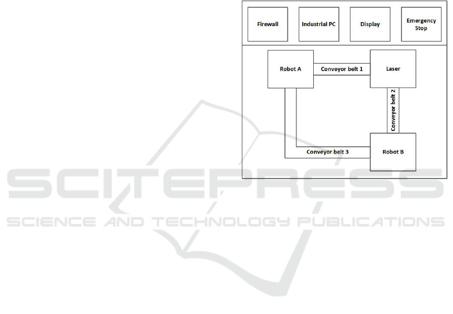
Figure 1: The demonstration use-case consisting of differ-
ent components belonging to several categories (i.e. me-
chanics, visualization, security etc.).
To illustrate the implemented techniques Figure 1 de-
picts a demonstration use-case. The use-case con-
sists of a manufacturing system with two robots and
a laser connected by three conveyor belts. Robot A is
used to place items into carriages on conveyor belt 1.
The filled carriages are then transported to the laser
and subsequently transferred to Robot B through con-
veyor belt 2. Robot B takes the lasered items from the
carriages. The empty carriages themselves are then
transported back to Robot A by conveyor belt 3. Over-
all, the manufacturing system is controlled through an
industrial PC attached to a firewall. For interaction
with the operator, a display is connected to the indus-
trial PC. Additionally, human operators are protected
by an emergency stop functionality.
In this example, views are utilized to divide the
manufacturing system into distinct parts e.g. Mechan-
ics, Visualization, Security etc. The robots, conveyor
belts and the laser as well as the industrial PC all need
mechanical structures in order to be placed in a pro-
duction plant. The planning and installation of these
components is done by mechatronic engineers. On
the other hand, the robots and the industrial PC run a
certain kind of software. Thus, the programming and
ICAART 2016 - 8th International Conference on Agents and Artificial Intelligence
282

administration of this software is done by software en-
gineers. Visualisation (i.e. user interface design) is
a completely different discipline and requires experts
familiar with human machine interfaces. Contrary to
that, security or safety related components must be in-
stalled by personnel especially trained for these kinds
of tasks.
When the automation system depicted in Figure 1
is designed, each member of the design team starts by
specifying the initial requirements of his subsystem.
This is done by choosing abstract entities from a list
of templates (seen in Figure 1). Each template may
have some attributes like power consumption, maxi-
mum weight, maximum temperature, speed etc. After
all abstract entities have been selected, the details and
relations between those must be specified. This is the
point where constraints are added. In this case, con-
straints could be the speed of the conveyor belts, cycle
time of the underlying fieldbus or the available band-
width.
It follows from this example that the design of an
automation system is very complex. The present ap-
proach can greatly simplify the effort required. This is
done by finding conflicted constraints during the spec-
ification and point those out to users. It is conceivable
that the security expert requires that the firewall has a
maximum bandwidth of 100 Mbit/s. Conversely, the
expert for the industrial PC might require a bandwidth
of 1 Gbit/s (see Figure 2).
When a number of unsatisfiable constraints are en-
countered, the goal is to display only the absolute
minimum number of necessary changes to the user.
This entails that only a minimum number of views,
and thus persons, are affected. To accomplish this, the
next section shows how minimum correction subsets
can be found.
4 MINIMUM CORRECTION SETS
In order to attribute all unsatisfiable constraints to a
certain view, a method is needed to determine exactly
which constraints could not be satisfied. This is ac-
complished by the use of Minimum Correction Sub-
sets (MCS) and Maximum Satisfiable Subsets (MSS).
The MCS, formally defined below, contains all unsat-
isfied constraints. This section describes how each
constraint is augmented with an additional boolean
variable which is used to determine the MCS.
For this, the proposed approach introduces a tech-
nique using a Constraint Satisfaction Optimisation
Problem (CSOP) to find MCSs for an unsatisfiable
CSP. As opposed to approaches discussed in (An-
sotegui et al., 2013) and (Kuegel, 2010) this work
proposes to augment a CSP in such a way, that it
can be transferred into a CSOP subsuming the CSP
and a MaxSAT problem for maximizing the num-
ber of satisfied constraints. The result of solving the
CSOP are value assignments to all problem variables
and truth assignments to boolean variables indicating
which constraints can and which cannot be satisfied,
as well as the constraints themselves.
A MCS is a set of constraints which needs to be
omitted from a CSP in order to make it satisfiable.
Conversely, the maximum satisfiable set contains the
maximum amount of clauses which can be satisfied
without making the CSP unsatisfiable. Therefore, the
MSS is the inverse of the MCS. The minimum un-
satisfiable set (MUS) describes the so called cause of
the unsatisfiability. A MUS consists of a set of con-
straints from which one constraint needs to be omit-
ted to achieve satisfiability. In this work, the MUS
is not necessary because the focus is to find the min-
imum set of unsatisfiable constraints (MCS) in order
to make the CSP satisfiable. To illustrate the approach
described in this paper, the following definitions are
necessary (Marques-Silva et al., 2013; Liffiton and
Sakallah, 2005).
Definition 1. The subset U ⊆ C is a MCS, iff C \ U is
satisfiable and ∀c ∈ U, C \ (U \ {u}) is unsatisfiable.
Definition 2. The subset S ⊆ C is a MSS, iff S is
satisfiable and ∀c ∈ C \ S, S ∪ {c} is unsatisfiable.
The MaxSAT problem can be stated as follows
(Kuegel, 2010). Given a formula in conjunctive nor-
mal form (CNF), try to satisfy as many clauses as pos-
sible. A CNF of a boolean formula can be expressed
as
V
n
l=0
C
l
where n ∈ N, l ∈ N is the number of
clauses. With C
l
=
W
m
n
k=0
(¬)x
lk
, where m
n
∈ N
is the number of literals and x can be either true or
false. ¬x
lk
is therefore the negation of x
lk
. Each C
l
will henceforth be called a clause. If the maximum
number of satisfiable clauses can be determined, it
is also possible to determine the MCS, since this set
consists of all the clauses which are left unsatisfied.
Subsequently the MSS can be determined, since it is
the difference of all constraints C and the MCS. In
this case, one MCS is used to notify the user which
constraints do not match and need to be removed or
relaxed. By replacing clauses by arbitrary predicates
which are boolean functions of arbitrary constraints a
MAX-CSP is obtained. This is realised as follows.
Upon validation of the constraints during the de-
sign process, every constraint c
m
, c ∈ C, m ∈ N is a
predicate that is the logical consequence of a boolean
indicator variable, b
m
∈ B, m ∈ N, so that b
m
im-
plies constraint c
m
. This means, any CSP solver is
able to find solutions where c
m
must hold (b
m
is true)
Exposing Design Mistakes During Requirements Engineering by Solving Constraint Satisfaction Problems to Obtain Minimum Correction
Subsets
283

and solutions where c
m
is not required to be satisfied
(b
m
is false).
In order to convert the CSP to a CSOP prob-
lem which objective is maximum satisfiability the fol-
lowing objective function is used. The set B
∗
=
{true, false}
|B|
is the set of all possible value assign-
ments for all b ∈ B. The function
val(b
∗
, i) =
(
b
i
= true → 1
b
i
= false → 0
(1)
gets a value assignment b
∗
∈ B
∗
and the index
of a variable b
i
∈ B and returns 1 if b
i
is assigned
the value true and 0 otherwise. The objective is to
maximize the number of satisfied constraints. This is
equal to finding the value assignment out of B
∗
with a
maximum number of variables in B that are assigned
the value true and for which the CSP is satisfiable:
argmax
b
∗
∈B
∗
|B|
X
m=0
val(b
∗
, m)
where
|C|
^
m=0
b
m
→ c
m
= true, b
m
∈ b
∗
(2)
The optimisation is realised by applying a con-
straint solver which maximises the objective func-
tion. As the input for the solver, the FlatZinc (Becket,
2015) format is used. This format is a solver inde-
pendent modelling language for constraints. Besides
the obvious standard predicates for specifying con-
straints, the FlatZinc format also allows to specify
global predicates. These are used to optimize certain
tasks which would be too inefficient when performed
without global predicates. Examples for those tasks
are counting, set operations, or sorting. All global
constraints are solver specific extensions to FlatZinc.
Thus not all global constraints are available on all
solvers which support FlatZinc.
In the use-case described in this paper, the FlatZ-
inc script is built as follows: The objective in for-
mula 2 is realised by mapping all boolean values of
the variables b
m
to integer variables that are arranged
in an array. The summing up of the array is done by
the global predicate count(.) and constrained to equal
the integer variable Out, where Out is assigned the
outcome of formula 2. This variable’s value is maxi-
mized by constructing a FlatZinc script with the solve
options
”solve maximize Out”
The keyword solve specifies that all lines above the
statement will be used for the solution. Maximize
states that the goal is to maximise the variable indi-
cated by the next word (Out).
To summarise, a robust method has been devised
in which it suffices to let a help-variable (b
m
) imply
each constraint. Subsequently, an aggregation func-
tion can be employed, whose output is a single vari-
able Out. This output can be maximised by a standard
off-the-shelf constraint solver that, for example, uses
branch and bound techniques for optimisation.
5 IMPLEMENTATION
The presented technique was implemented in an ap-
plication called ”assisted design for automation sys-
tems (AD4AS)”. The software, developed as a pro-
totype, realises an iterative, holistic design approach
for automation systems. One major focus of the work
is to divide elicitation of requirements into different
categories, called Views. These were first mentioned
in (T
¨
orngren et al., 2014) and (Nie et al., 2013). They
state that any complex system will involve multiple
stakeholders and multiple views. Additionally, the re-
lationship between different stakeholders in a project
is evaluated with the goal of an optimal integration
of each stakeholder. It is stated that stakeholders
with backgrounds in different disciplines may have
diverse vocabularies and understandings of the same
concepts. From this follows that in design software it
is necessary to include support for helping users with
different professions collaborate.
As indicated in the introduction, in the present ap-
proach each view displays components of a certain re-
quirements category. One category could be the me-
chanical structure of the automation system. Other
categories are the visualisation of process parameters
or security related components. These different views
help to divide the requirements elicitation into parts.
Each part can be designed by experts in the appropri-
ate discipline.
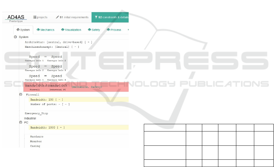
Figure 2 shows the prototype’s user interface. At
the top, different design steps can be selected. In the
next line the views are visible as well as the button to
start the validation of the design. The currently imple-
mented views are: system (overview), mechanics, vi-
sualisation, security, process and product. Below, the
list of selected abstract components, i.e. templates,
can be seen.
By taking advantage of the compartmentalisation
made possible by the views, each member of a de-
sign team can concentrate on his own speciality. This
means, when unsolvable constraints are encountered
during the automated design, the solution of these
constraints can be delegated to the specific team mem-
ber in whose subject area the unsatisfied constraints
fall. This way, each area of an automation system can
ICAART 2016 - 8th International Conference on Agents and Artificial Intelligence
284
be covered by domain experts. Thus, design time can
be reduced and the quality of the design is improved.
The process simplifies the work by enabling the
design team to focus on abstract, conceptual ideas
(i.e. specifying the requirements) instead of having
to work out every detail. The advantage is that the
software is able to find inconsistencies among the re-
quirements of the system. With this information, each
inconsistency can be attributed to a specific subject
by using the concept of views. Additionally, the pre-
sented prototype frees users of the tedious work to
select products from a range of different vendors to
conform to every requirement in the system’s specifi-
cation. Instead, a catalogue of permitted components
can be supplied and the software will decide which
components can be used and how those should be
ordered hierarchically. As section 6 shows, the pre-
sented approach scales sufficiently well for many au-
tomation systems.
Figure 2: The AD4AS user interface when unsatisfied con-
straints are encountered
When the design from figure 1 is validated in
AD4AS, the software will ensure that the maximum
number of constraints can be satisfied. If it is assumed
that in this case all other constraints are satisfied (for
example conveyor speed, energy consumption etc.)
the software will show, which constraint is left un-
satisfied (i.e. bandwidth). Furthermore, the system
determines that the unsatisfied constraint is located
in the views mechanics and safety. Thus the secu-
rity expert and the industry PC administrator can find
a solution without affecting the designers of the user
interface for example. When different MCSs with the
same number of conflicts are found, the user can de-
cide which of the MCSs he wants to solve.
6 RESULTS
In (Fay et al., 2015) was established that in practice,
automation engineers are often given no time to define
requirements formally. The present approach works
toward making the formal design of automation sys-
tems faster and more consistent. The provided plat-
form incorporates techniques determined to be useful
to increase the overall design efficiency (i.e. the con-
cept of views and validation of constraints). Further-
more, the constraint validation has been extended to
attribute each constraint to one or more views. To
accomplish this, a way to transform the EFM into
a CSOP problem and thus satisfying the maximum
number of constraints has been implemented.
Table 1 shows the runtime of the proposed algo-
rithm as performed on a 64-Bit PC with Intel Core i5
CPU with 2.67 GHz, 8 GB memory and Windows 7
operating system. The test set has been created from
randomly generated extended feature models with a
branching factor between 5 and 10 and each feature
having two attributes. The branching factor describes
how many child features each parent feature has. The
maximum depth of an EFM was set to 6. One attribute
a
i1
is limited by a constraint c
i
with c
i
: a
i1
< r,
r ∈ R and a fixed domain size. Additionally, the sec-
ond attribute a
i2
of each feature is limited by a con-
straint of the same form, but with a randomly varying
domain.
Table 1: Runtime (milliseconds) compared to the number
of variables and constraints.
Variables 54 199 2021 2824 21379
Solvable Con-
straints
1 10 237 406 3111
Unsolvable
Constraints
7 20 37 14 31
Runtime (ms) 1 2 20 35 2023
The AD4AS software is an assistance system
which supports designers in specifying requirements
for automation systems iteratively. The standard use-
case is that designers enter requirements to achieve a
functioning system. Therefore, the ratio of unsatisfied
to satisfied constraints is small.
The work in (Nie et al., 2013) gives three exam-
ples of industrial applications. The examples illus-
trate the amount of variables and constraints com-
monly found in real-world applications. The first and
second example describe a subsea production system
Exposing Design Mistakes During Requirements Engineering by Solving Constraint Satisfaction Problems to Obtain Minimum Correction
Subsets
285

and a video conferencing system, respectively. These
consist of approximately 500 variables. Whereas the
third example, a vessel prognostics and health man-
agement system, consists of approximately 1000 vari-
ables. These examples illustrate the numbers in Table
1 which show that the proposed approach is sufficient
for configuring today’s automation systems. With the
calculation of the minimum correction subsets inte-
grated into the software described in section 5, a tool
is created which enables engineers to design automa-
tion systems very efficiently. Furthermore, even sys-
tems with several thousand components can be easily
formulated and checked for consistency.
7 CONCLUSION
In this paper a holistic approach to designing automa-
tion systems is presented. Based on the work intro-
duced in (T
¨
orngren et al., 2014) and (Nie et al., 2013),
it is shown that our work contributes to greatly sim-
plify and speed up the design of an automation sys-
tem. The most important point is that through the
presented work system designers can concentrate on
high-level specifications in their field of knowledge
while certain details and implementation specific as-
pects are added automatically. Overall, the presented
approach aides designers in two ways. On the one
hand, the design is compartmentalised to accommo-
date the need that experts with different backgrounds
and professions interpret designs in different ways
(see (T
¨
orngren et al., 2014)). This means, in order to
achieve maximum efficiency, each expert should be
best put to work with a vocabulary and concepts he is
most familiar with. On the other hand, the AD4AS
prototype finds each unsatisfied constraint within a
system and can attribute it to different views (i.e. ex-
perts). Furthermore, we showed in section 6, that
finding unsatisfied constraints can be done in reason-
able time for the amount of components usually found
in automation systems. Therefore, the suggestions
from (Fay et al., 2015) and (T
¨
orngren et al., 2014)
were implemented and extended to construct a proto-
type which can contribute to close the gap between
the increasing complexity of automation systems and
automated design tools.
ACKNOWLEDGEMENT
Funded by the German Federal Ministry of Education
and Research, ’Design Methods for Automation Sys-
tems with Model Integration and Automatic Variation
Validation’, 16M3204B.
REFERENCES
Ansotegui, C., Bonet, M. L., and Levy, J. (2013). Sat-based
maxsat algorithms. Artificial Intelligence, 196:77–
105.
Bartak, R. (1999). Constraint programming: In pursuit of
the holy grail. In in Proceedings of WDS99 (invited
lecture), pages 555–564.
Becket, R. (2015). Specification of flatzinc-version 1.6.
Benavides, D., Cort
´
es, R. A., and Trinidad, P. (2004).
Coping with automatic reasoning on software product
lines. In Proceedings of the 2nd Groningen Workshop
on Software Variability Management.
Benavides, D., Segura, S., and Ruiz-Cort
´
es, A. (2010). Au-
tomated analysis of feature models 20 years later: A
literature review. Information Systems, 35(6):615–
636.
Bofill, M., Palah
´
ı, M., Suy, J., and Villaret, M. (2012). Solv-
ing constraint satisfaction problems with sat modulo
theories. Constraints, 17(3):273–303.
B
¨
ottcher, B., Moriz, N., and Niggemann, O. (2014). From
formal requirements on technical systems to complete
designs - a holistic approach. In Schaub, T., Friedrich,
G., and O’Sullivan, B., editors, 21st European Con-
ference on Artificial Intelligence, volume 263 of Fron-
tiers in Artificial Intelligence and Applications, pages
977–978.
Chakrabarti, A., Shea, K., Stone, R., Cagan, J., Camp-
bell, M., Hernandez, N. V., and Wood, K. L.
(2011). Computer-based design synthesis research: an
overview. Journal of Computing and Information Sci-
ence in Engineering, 11(2):021003.
Czarnecki, K. and Eisenecker, U. W. (2000). Generative
programming: methods, tools, and applications.
Czarnecki, K., Hwan, C., Kim, P., and Kalleberg, K. (2006).
Feature models are views on ontologies. In Software
Product Line Conference, 2006 10th International,
pages 41–51. IEEE.
Fay, A., Vogel-Heuser, B., Frank, T., Eckert, K., Hadlich,
T., and Diedrich, C. (2015). Enhancing a model-based
engineering approach for distributed manufacturing
automation systems with characteristics and design
patterns. Journal of Systems and Software, 101(0):221
– 235.
Felfernig, A., Benavides, D., Galindo, J., and Reinfrank, F.
(2013). Towards anomaly explanation in feature mod-
els. In Workshop on Configuration, Vienna, Austria,
pages 117–124.
Freuder, E. C. and Wallace, R. J. (1992). Partial constraint
satisfaction. Artificial Intelligence, 58(1):21–70.
Gruner, S., Weber, P., and Epple, U. (2014). Rule-based en-
gineering using declarative graph database queries. In
Industrial Informatics (INDIN), 2014 12th IEEE In-
ternational Conference on, pages 274–279.
Gu, J., Purdom, P. W., Franco, J., and Wah, B. W.
(1999). Algorithms for the satisfiability (sat) problem.
Springer.
Jiang, Y., Kautz, H., and Selman, B. (1995). Solving prob-
lems with hard and soft constraints using a stochas-
tic algorithm for max-sat. In 1st International Joint
ICAART 2016 - 8th International Conference on Agents and Artificial Intelligence
286

Workshop on Artificial Intelligence and Operations
Research. Citeseer.
Koshimura, M., Zhang, T., Fujita, H., and Hasegawa, R.
(2012). Qmaxsat: A partial max-sat solver. Journal
on Satisfiability, Boolean Modeling and Computation,
8:95–100.
Kuegel, A. (2010). Improved exact solver for the weighted
max-sat problem. POS@ SAT, 8:15–27.
Kumar, V. (1992). Algorithms for constraint-satisfaction
problems: A survey. AI magazine, 13(1):32.
Liffiton, M. H. and Sakallah, K. A. (2005). On finding all
minimally unsatisfiable subformulas. In Theory and
Applications of Satisfiability Testing, pages 173–186.
Springer.
Maher, M. L. (1990). Process models for design synthesis.
AI magazine, 11:49.
Marques-Silva, J., Heras, F., Janota, M., Previti, A., and
Belov, A. (2013). On computing minimal correction
subsets. In Proceedings of the Twenty-Third interna-
tional joint conference on Artificial Intelligence, pages
615–622. AAAI Press.
Mendonca, M., Wa¸sowski, A., and Czarnecki, K. (2009).
Sat-based analysis of feature models is easy. In Pro-
ceedings of the 13th International Software Product
Line Conference, SPLC 09, pages 231–240, Pitts-
burgh, PA, USA. Carnegie Mellon University.
Moriz, N., B
¨
ottcher, B., Niggemann, O., and Lackhove, J.
(2014). Assisted design for automation systems - from
formal requirements to final designs. In 19th IEEE
International Conference on Emerging Technologies
and Factory Automation (ETFA), Barcelona, Spain.
Nie, K., Yue, T., Ali, S., Zhang, L., and Fan, Z. (2013).
Constraints: the core of supporting automated product
configuration of cyber-physical systems. In Model-
Driven Engineering Languages and Systems, pages
370–387. Springer.
Rinc
´
on, L., Giraldo, G., Mazo, R., Salinesi, C., and Diaz, D.
(2015). Method to identify corrections of defects on
product line models. Electronic Notes in Theoretical
Computer Science, 314:61–81.
Tamura, N., Taga, A., Kitagawa, S., and Banbara, M.
(2009). Compiling finite linear csp into sat. Con-
straints, 14(2):254–272.
Tamura, N., Tanjo, T., and Banbara, M. (2008). System
description of a sat-based csp solver sugar. Proc. 3rd
International CSP Solver Competition, pages 71–75.
T
¨
orngren, M., Qamar, A., Biehl, M., Loiret, F., and El-
Khoury, J. (2014). Integrating viewpoints in the de-
velopment of mechatronic products. Mechatronics,
24(7):745–762.
Vogel-Heuser, B., Sch
¨
utz, D., Frank, T., and Legat, C.
(2014). Model-driven engineering of manufactur-
ing automation software projects - a sysml-based ap-
proach. Mechatronics, 24(7):883 – 897. 1. Model-
Based Mechatronic System Design 2. Model Based
Engineering.
Exposing Design Mistakes During Requirements Engineering by Solving Constraint Satisfaction Problems to Obtain Minimum Correction
Subsets
287
