A Concept of Ultraviolet Lithography System and Design of its Rear
Part using Artificial Intelligence for Starting Design
Irina Livshits and Nenad Zoric
International Research Lab “InformationTechnologies in Optical Design & Testing”,
ITMO University, Birgevaya line, bld.14-16, Saint Petersburg, Russian Federation
Keywords: Lithography, Optical Design, Projection Lens, UV, Artificial Intelligence, Starting Point.
Abstract: This paper describes a concept for designing a projection lens in lithographic optical system for 365 nm.
Our approach for meeting this objective is to use the starting design obtained by artificial intelligence mode
in Synopsys software. The proposed method describes the steps of getting a desired starting point of the
optical system and the optimization problems in the optical system with a high numerical aperture.
1 INTRODUCTION
Optical lithography is a photographic process of
using an optical image and a photosensitive film to
produce the patterned silicon wafers in
semiconductor manufacturing. The industry of
integrated circuits mostly is using this technique in
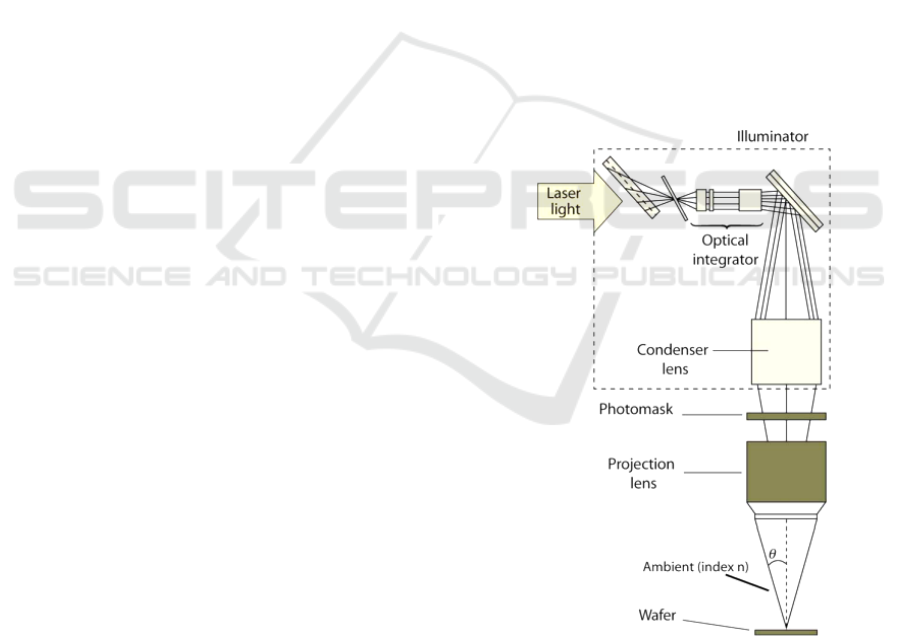
manufacturing process. In figure 1 it can be seen one
type of projection optical lithography system. The
source of ultraviolet light is the laser which shines
through the illuminator, which expands,
homogenizes, and conditions the beam in the
condenser. Further, the light goes through a photo -
mask, and the projection lens to the wafer which is
coated with a photosensitive film (Rothschild,
2005). Many technologies have been proposed to
improve the process of the optical lithography, but
so far none has succeeded to replace lithographic
systems (Harriott, 2001).
The driving forces which are pushing
lithographic systems beyond the limits are
decreasing wavelength and increasing numerical
aperture, while the solution space is limited by
several conflicting constraints such as diffraction
limited performance, reasonable overall dimensions,
minimum number of optical elements, availability of
material, limits on the angles (Ulrich, 2000).
Lithographic objectives are famous by its high
quality, and by many challenges in optimization of
the projection optical system (Levinson, 2005).
Hereby, we proposed a simple concept in developing
of the ultraviolet (UV) lithographic optical system
which can simplify the work of the optical designer
at the early stage of design.
Figure 1: Schematic of the lithographic optical system.
We divide the total lithographic lens into two
parts:
Condenser (front) lens with removed back exit
pupil, which could be understood as a reversed
lens with the removed forward entrance pupil;
84
Livshits, I. and Zoric, N.
A Concept of Ultraviolet Lithography System and Design of its Rear Part using Artificial Intelligence for Starting Design.
DOI: 10.5220/0005688500820086
In Proceedings of the 4th International Conference on Photonics, Optics and Laser Technology (PHOTOPTICS 2016), pages 84-88
ISBN: 978-989-758-174-8
Copyright
c
2016 by SCITEPRESS – Science and Technology Publications, Lda. All rights reserved
Projection (rear) lens with the removed forward
entrance pupil (Figure 1).
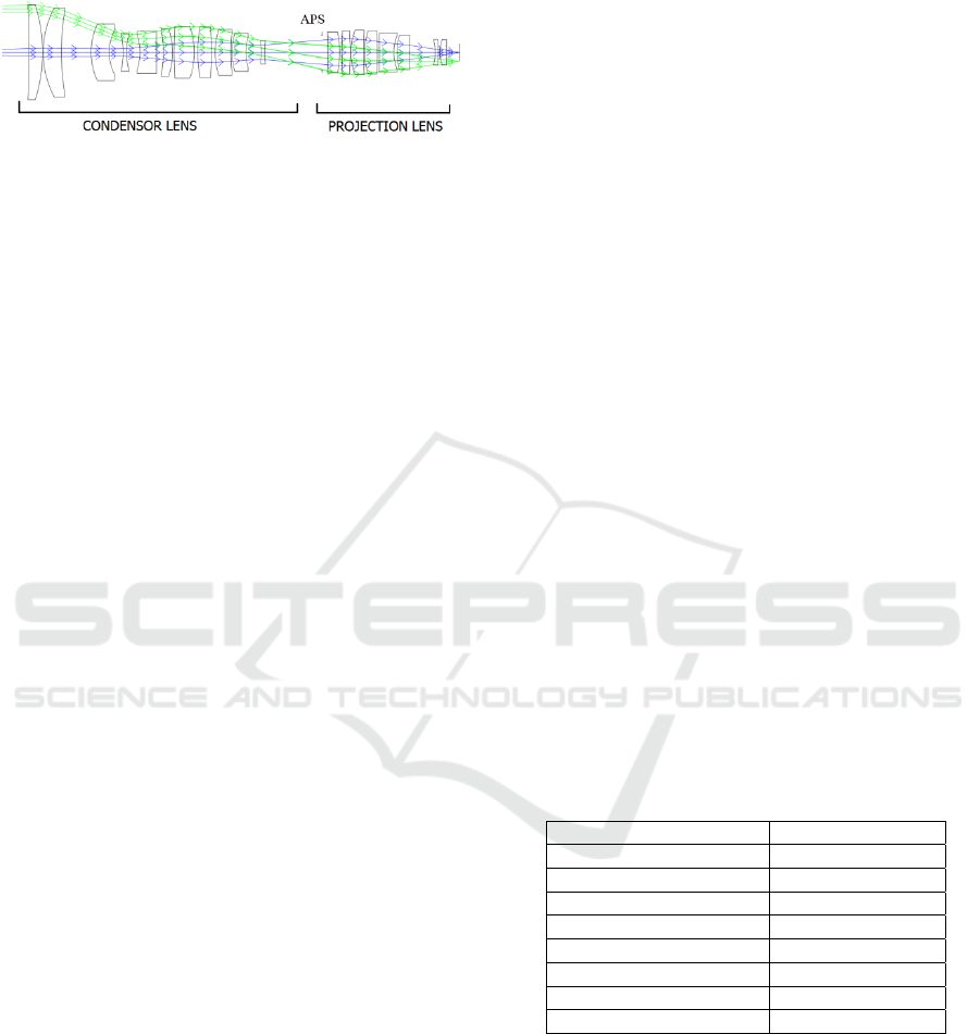
Figure 2: Schematic of the reference lithographic system.
Both parts can be designed separately as two
objectives with removed entrance pupil and
constraint of telecentric chief ray. An each part of
the lithographic optical system must be optimized as
good as possible in order to achieve diffraction
limited optical system when we connect designed
parts.
The desired specifications for proposed optical
system we used from a reference UV lithographic
system. Figure 2 shows our reference UV system: a
lithographic objective for 365 nm with aberrations
corrected up to diffraction-limit. The system is
defined by next characteristics : F number is 1.2, the
Gaussian image height is 9 mm, image distance is
22 mm and the magnification is - 0.2. The
spectrum range of lithographic lens is ultraviolet
(UV) with wavelengths: 362 nm, 365 nm and 368
nm; principle color is 365 nm. In our case we have
split the total lithographic system at the place of
aperture stop (APS) where the chief ray angle has a
minimum.
The starting point for a projection (rear) part of
the lithographic system was obtained by the artificial
intelligence (A.I.) mode in Synopsys software, and
optimized by the merit functions for transverse and
OPD aberrations.
2 STARTING DESIGN OF THE
PROJECTION LENS
In order to keep the specification of a total optical
system we have derived the specifications of the
projection part. Focal length 100 mm was chosen for
the projection part in order to keep the total length of
a reference system. We have calculated the field
angle using formula (1)
ὡ = Arctg (y’/f’) (1)
where ὡ is the chief ray angle, y’ is gaussian
image hight and f’ is a focal length of the projection
lens. The image distance we kept 22 mm the same as
in a reference litographic system.
Successfully choosing the starting system at the
early stages of development significantly shortens
the overall planning time (Livshits, 2007). In the
period of the wide applications of computers in
optical design, the speed of the ray tracing itself
increased thousand times, but the speed of new
schemes creation is not so fast, approximately 2-3
times. The main reason is hidden in the unsuccessful
starting point selection, If selected scheme doesn’t
have enough correction features, no computer can
add them without optical designer. In order to obtain
good starting point for projection lens we were using
artificial intelligence (A.I) mode in Synopsys
software.
Artificial intelligence capability is the expert
systems program within Synopsys software. A
general set of requirements may be input, and Macro
will find the 10 best designs that most closely match
them when the scale and aperture are adjusted as
well as possible. Applied algorithm is one that
employs a tree-structured logic wherein decisions
are derived from the responses of a number of
experts (their experience) in a particular field to a
lengthy debriefing (Dilworth, 2013).
DSearch macro (Design Search) is searching
through lens space in order to find an attractive
starting point. We give it the desired system
parameters and the number of elements we want,
along with some target quantities to define the
design goals. It constructs a series of candidate
lenses, with initial dimensions assigned according to
either a binary search scheme or randomly,
depending on user input.
Table 1: Specifications for the starting point of design.
Specification Value
Object distance Infinite
Object height Infinite
Marg. ray height 41.67 mm
F/Number 1.2
Chief ray angle 5.69 degrees
Focal length 100 mm
Gaussian image height 9 mm
Image distance 22 mm
The default option assigns element powers
according to the bit in a binary number that is
incremented at each cycle. Thus, if you request, a
four-element lens, the first lens would have all
negative elements taken from the binary number
(0000). The next try would have one positive
element, from the number 0001.
In Table 1 are presented the specifications for the
starting point of our projection lens. It is desired that
a bulge of the lithographic optical system possess
A Concept of Ultraviolet Lithography System and Design of its Rear Part using Artificial Intelligence for Starting Design
85
more positive lenses. In order to achieve this goal
we have been starting with the smaller system, with
shorter focal length and smaller marginal ray height.
In DSearch macro we have defined characteristics of
our system:
TIME
DSEARCH 1 QUIET
SYSTEM
OBB 0 5.69 5
UNI MM
WAVL .368 .365 .362
END
GOALS
ELEMENTS 7
FNUM 1.2
BACK 2.1
STOP FIRST
STOP FIXED
GLASS POS
O S-FSL5Y
GLASS NEG
O PBM2Y
END
SPECIAL
ACM 3 1 1
ACC 5 1 1
M 0 100 A P HH 1
END
GO
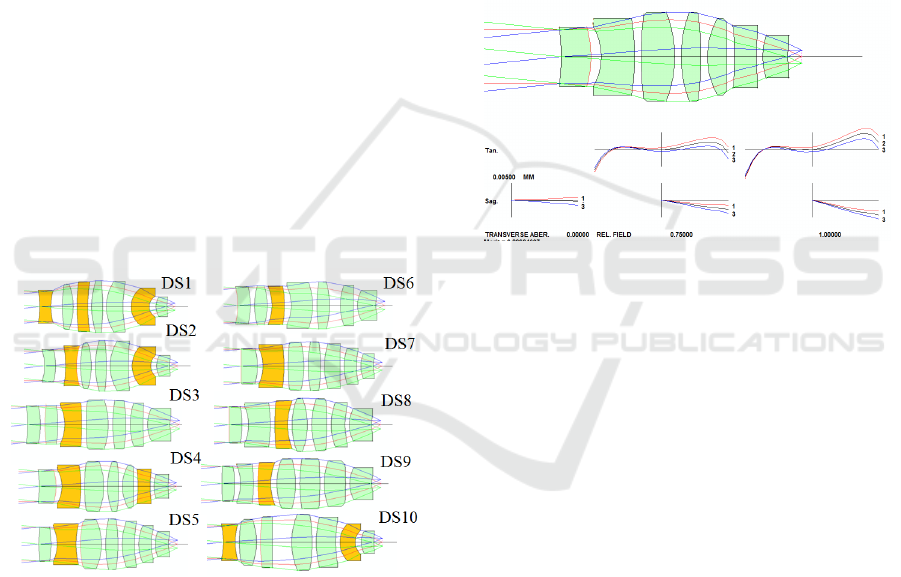
Figure 3: Starting points obtained by DSearch macro.
Section OBB 0 5.69 5 defines field angle 5.69 and
marginal ray height 5. Next section WAVL .368
.365 .362 defines wavelengths; number of lenses
ELEMENTS 7; Fnumber FNUM 1.2; back focal
length, BACK 2.1. We demand aperture stop at the
first surface STOP FIRST, STOP FIXED; section
which defines minimum and maximum lens
thickness ACM 3 1 1, ACC 5 1 1; and special
section where we define constraint for telecentricity
SPECIAL M 0 1 A P HH 1. In this particular case,
estimated time is around 90 minutes, while DSearch
macro is searching for 10 best candidates for starting
design. We have defined in macro 7 elements
(lenses) in order to decrease number of lenses in our
design comparing it to the reference projection lens.
Obtained 10 starting designs for projection part are
shown in Figure 3. The positive lenses are marked
by green, while the negative lenses are marked by
yellow color. It can be seen that we reach our goal
to get more positive lenses in the system bulge. The
logical decision related to decreasing of the aperture
is to have more positive lenses in a bulge. By
comparing the transversal aberrations of all ten
candidates and number of positive lenses in a bulge
of the systems the seventh design search (DS7) was
chosen as the most appropriate.
Figure 4: Starting point for projection lens obtained by
DSearch macro.
DS 7 has one negative lens closer to the aperture
stop; it is shorter than others obtained starting points
with much better sagital transversal aberration in
range 0.005 mm. On another hand, we obtained the
optical system having the short focal length 9 mm
and thin lenses. In the next step we have scaled focal
length (f) to 100 mm. In this way we reached the
desired characteristics of the optical system shown
in Table 1. The chosen starting design DS7 is shown
in Figure 4, having 6 positive elements of total 7
elements. After the chosen lens DS7 is scaled to
focal length 100 mm, the transversal aberrations are
in range 0.05 mm.
3 OPTIMIZATION OF THE
PROJECTION LENS
The issue of optimization of the lithographic
objectives is probably the most difficult one in the
optical system optimization. Usually the modern UV
lithographic objectives have more than twenty
components having aspheric surfaces. That results in
more than one hundred optimization variables. The
PHOTOPTICS 2016 - 4th International Conference on Photonics, Optics and Laser Technology
86
most important constraints are the magnification,
total track and telecentricity. (Mack, 2006)
Considering all these issues, the optimization of the
projection lens should be easier than the
optimization of the total lithographic system because
of the less optimization variables and less number of
the lenses. However, the design of optical system
with high aperture is challenging work. Increasing
NA has meant increasing the acceptance angle of the
lens (Kawata, 1989). This process has had to
overcome significant challenges in optical design
and fabrication because the lens must be near
aberration-free and the image size must be kept
large, ~4 mm x 26 mm. Despite these difficulties,
the NA of projection systems has grown steadily,
from 0.5 in around 1990 to over 0.8 in 2004, with
plans to exceed 0.9 in the future.
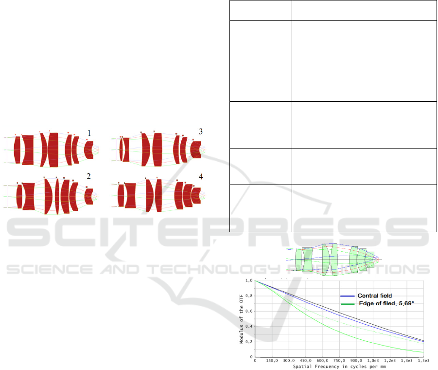
Figure 5: Steps of the optimization in design of projection
lens.
Our referent lithographic system having NA 0,52,
for 365 nm, was chosen in order to be designed just
by the lenses, avoiding utilization of the mirrors
(Born, 1999). The starting design DS7 of
lithographic projection lens obtained in Synopsys
was optimized in Synopsys by using a merit function
for transversal and OPD aberrations as well in
Zemax by using a default merit function for the best
focus, RMS Spot Radius, Centroid RA 18x18 having
the constraints for a telecentric chief ray. Figure 5
shows the few steps in the process of optimization.
It can be seen that we have been keeping logic of
projection lens having a bulge and positive lenses
which decreasing numerical aperture.
In Table 2 are explained the few applied steps, in
Synopsys software, during process of the
optimization of the starting design. The final design
of the projection part and its MTF (modulation
transfer function) are shown in Figure 6.
Developed projection part is optimized close to
diffraction limit for central field angle (Figure 6.)
Longitudinal aberrations are in range 0.00112 mm,
while distortion has to be more decreased up to zero.
Total length of developed projection lens system is
310 mm what is one disadvantage compared to the
reference projection part of total system. It could be
improved in further work, where we intent to
develop the total lithographic lens by connecting a
projection part of system with the condenser part.
Table 2: Optimization steps of the projection lens.
Optimization
step
Description
1. step
Starting design from 0.05 transv.
aberration, aperture stop was
added, design was optimized with
default merit function, 3*6 full
grid, constraints 35 mm max
thickness, biggest weights for third
order aberrations
2. step
New merit function with additional
rays for wave front aberrations- full
grid, bigger weights for astigmatic
curve
3. step
Merit function with more
additional rays in field zone for
OPD (optical path difference)
4. step
Merit function for OPD, changing
weights for particular aberrations
in order to get better MTF on axis
and transverse aberration scale
Figure 6: Designed projection lithographic lens with its
MTF.
4 CONCLUSIONS
We have presented a method for designing
projection part of lithographic lens using artificial
intelligence for starting points which should to
simplify the early stage in design of the lithographic
optical system. By using Dsearch macro we showed
the way how to obtain desired starting design with
more positive lenses in a bulge of the lithographic
system. Starting design of projection lens was
A Concept of Ultraviolet Lithography System and Design of its Rear Part using Artificial Intelligence for Starting Design
87

optimized close to diffraction limited optical system,
and the main steps in applied optimization were
explained. In additional, designed projection part it
can be more optimized in order to reach diffraction
limited system. Proposed method can be easily
adopted for the starting design of any optical system
having more positive lenses. Further work will be
design of front (condenser) part using artificial
intelligence for starting design, and final design of
total lithographic optical system.
ACKNOWLEDGEMENTS
The research leading to these results has received
funding from the People Programme (Marie Curie
Actions) of the European Union's Seventh
Framework Programme (FP7/2007-2013) under
REA grant agreement no. PITNGA-2013-608082
‘ADOPSYS’.
REFERENCES
Rothschild M., 2005. Projection optical lithography,
Materials Today, Elsevier.
Harriott, L. R., 2001. "Limits of lithography," Proceedings
of the IEEE. vol.89, no.3.
Levinson, H. J., 2005. Principle of Lithography, SPIE
Press, Bellingham, Washington, Second Edition.
Livshits I. L., Sal'nikov A. V., and Cho U., 2007.
Choosing the starting system for designing objectives,
J. Opt. Technol. 74.
Ulrich W., Beiersdoerfer S., Mann H.J., 2000. Trends in
optical design of projection lenses for UV and EUV
lithography, Proc. SPIE 4146, Soft X-Ray and EUV
Imaging Systems.
Dilworth D. C., Shafer D., 2013. Man versus Machine; a
Lens Design Challenge”, SPIE Vol. 8841, 88410G-1.
Mack C., 2007. Fundamental Principles of Optical
Lithography: The Science of Microfabrication. Wiley-
Interscience, New York.
Born M. and Wolf E., 1999. Principles of Optics:
Electromagnetic Theory of Propagation, Interference
and Diffraction of Light, Cambridge University Press.
Cambridge, New York, Seventh Edition.
Kawata H., Carter J. M., Yen A., and Smith H. I., 1989.
Optical projection lithography using lenses with
numerical apertures greater than unity,
Microelectronic Engineering 9. .
PHOTOPTICS 2016 - 4th International Conference on Photonics, Optics and Laser Technology
88
